Hydrotechnik HTE2 User manual

Ba_Ref-E2D2C2 • 09/2022
Digital Pressure Gauges Types
HTE2/D2/C2 & HTE2-L-E2/D2/C2
Operating manual
...............................................page 20 – 36
T E S T E N G I N E E R I N G L T D
Cert. 00007
HTE2 & HTE2-L Operating manual
Hydrotechnik UK Test Engineering Ltd, 1 Central Park, Lenton Lane, Nottingham, NG7 2NR, UK

E2 / D2 / C2
-20 - Ba_Ref-E2D2C2 • 09/2022
Table of contents page
0About This Operating Manual..................................................................................20
1Safety Instructions...................................................................................................21
2Device Description ..................................................................................................22
3Structure..................................................................................................................23
4Connection and Battery Replacement.....................................................................24
5Operation ................................................................................................................26
6Data Logger ............................................................................................................28
7Maintenance and Return Shipment.........................................................................29
8Disassembly and Disposal ......................................................................................30
9Technical Data ........................................................................................................31
10 EU Declaration of Conformity.................................................................................. 36
0 About This Operating Manual
•Read carefully before use!
•Retain for later reference!
Symbols used:
WARNING
Failure to do so may result in death or serious injury.
CAUTION
Failure to do so may result in minor or moderate injury.
IMPORTANT
Failure to do so may result in damage to property and the environment.
If you have any problems or questions, please contact your supplier or contact us directly at:
Hydrotechnik UK Ltd.
1 Central Park, Lenton Lane
Nottingham NG7 2NR / United Kingdom
+44(0)115 900 3550
www.hydotechnik.co.uk
Copyright notice
The reproduction, distribution and utilization of this operating manual as well as the communication
ofits contents toothers without express authorization is prohibited. Offenders will be held liable for
the payment ofdamages. All rights reserved in the event ofthe grant of a patent, utility model or
design.
Exclusion of liability
We accept no liability for any damage or malfunctions resulting from incorrect installation, inappropri-
ate use ofthe device or failure to follow the instructions in this operating manual.

E2 / D2 / C2 Safety Instructions
Technical changes reserved - 21 -
1 Safety Instructions
Read the operating manual carefully. Follow all instructions and notices to prevent injury or
damage to property.
Intended use
The digital pressure gauge may only be used for checking, adjusting and calibrating pressure
measuring devices.
The digital pressure gauge must not be used outside the specification or in violation of the
operating instructions.
WARNING
The digital pressure gauge is not a safety component in accordance with Di-
rective 2006/42/EC (Machine Directive).
Never use the device as a safety component.
The operational safety of the device supplied is only guaranteed by intended use. The speci-
fied limits (p. 31) may under no circumstances be exceeded.
This applies in particular to compliance with the permissible pressure range end value and
the permissible temperature range.
WARNING
Exceeding the maximum overload values can lead to material failure of the digital
pressure gauge. This can cause serious damage to health.
Make sure that the overload values are never exceeded.
Qualified personnel
•The personnel in charge of the installation, operation and maintenance of the device
must hold a relevant qualification. This can be based on training or relevant instructions.
General safety instructions
•Degree of protection according to EN 60529:
Ensure that the ambient conditions at the place of use do not exceed the requirements of
the specified degree of protection (p. 31).
•Only use the device in perfect condition. Damaged or faulty devices must be checked im-
mediately and replaced if necessary.
•Do not remove or destroy type plates or other markings on the device, or the warranty is
rendered null and void.

Device Description E2 / D2 / C2
-22 - Ba_Ref-E2D2C2 • 09/2022
2 Device Description
The types E2 / D2 / C2 are digital pressure gauges with actual value and MIN/MAX display.
They have an accuracy of ±0.5% Type E2, ±0.1% Type D2 and ±0.05% Type C2, relative to
the corresponding pressure range end value (FS).
Signals from the pressure measurement cells are recorded at a sampling rate of 10 ms
(100 measurements/s), converted into pressure values and displayed. Thanks to the high
sampling rate, dynamic pressure peaks can also be measured. They are written to the
MIN/MAX memory, which is continuously updated.
Versions
Standard
Version with data logger
Accuracy (from end value)
E2 0.5%
D2 0.1%
C2 0.05%
Pressure range
Resolution
-1...3 bar
1 mbar
-1...5 bar
1 mbar
-1...10 bar
1 mbar
-1...20 bar
1 mbar
-1...40 bar
10 mbar
-1...60 bar
10 mbar
0...100 bar
10 mbar
0...160 bar
10 mbar
0...250 bar
100 mbar
0...400 bar
100 mbar
0...700 bar
100 mbar
0...1000 bar
100 mbar

E2 / D2 / C2 Structure
Technical changes reserved - 23 -
3 Structure
Components
USB connection with protective cap (only
version with data logger).
Cast zinc housing with rubber protection
cap.
LC display with backlight.
Control panel with buttons.
G¼″ pressure connection.
Versions of rubber protection cap (rear side)
Rubber protection cap made of one piece
Rubber protection cap for opening
Display
Bar graph display.
Unit display.
MIN/MAX or Full Scale (FS).
Measured value display.

Connection and Battery Replacement E2 / D2 / C2
-24 - Ba_Ref-E2D2C2 • 09/2022
4 Connection and Battery Replacement
The digital pressure gauge has a G¼″ (BSPP) male thread and is supplied with batteries fit-
ted. The device is ready for operation after it is switched on.
WARNING
The connection (AF 27) is approved up to a nominal pressure of 1,000 bar.
Observe the nominal pressure specifications of the installed measuring con-
nections and the specified safety factors.
Improper installation of the pressure gauges and the corresponding adapters
can lead to the pressure gauges being torn off.
4.1 Connection
The housing of the digital pressure gauge can be rotated on the pressure connection. When
mounting directly, make sure that no attachments obstruct the rotation.
1. Prepare the measurement setup for connection
to the G¼″ pressure connection.
WARNING
Only use adapters with corresponding nominal
pressure specifications!
2. Make sure that the gasket is correctly seated in
the pressure connection.
3. Carefully turn the digital pressure gauge by
hand into the measurement setup thread.
4. Tighten the pressure connection with an open-
end wrench (AF 27).
WARNING
The mounting must be carried out with a torque of 25 Nm.
5. Align the digital pressure gauge for your application.

E2 / D2 / C2 Connection and Battery Replacement
Technical changes reserved - 25 -
4.2 Battery Replacement
The battery capacity is indicated by the number of bars (0…5 bars) in the battery symbol.
The batteries should be replaced when no bar is visible and the bat-
tery symbol flashes. The digital pressure gauge is still completely
functional.
The batteries must be replaced when the additional message
Lo bAtt appears. The digital pressure gauge is no longer opera-
tional.
1. Switch off the device.
If you have a rubber protection cap for
opening, you can simply remove the rubber
protection cap from the housing.
Otherwise, we recommend that you leave
the protection rubber cap on the housing
during battery replacement.
2. Open the housing:
Completely remove the screws from the
rear cover.
3. Lever the rear cover off the housing.
4. Set the rear cover aside.
5. Replace the batteries (LR6 - AA).
!!! Pay attention to the POLARITY !!!
NO HOUSEHOLD WASTE
The batteries must be disposed of.
6. Check the seat of the gasket in the rear
cover and watch out for signs of damage.
7. Carefully attach the rear cover to the hous-
ing.
8. Align the rear cover with the boreholes.
9. Re-tighten the rear cover screws with
0.6 Nm.

Operation E2 / D2 / C2
-26 - Ba_Ref-E2D2C2 • 09/2022
5 Operation
Button
1. function
2. function
(press for 2 s)
Switch the device on or off
Switch on backlight (20 s)
Display MIN, MAX or full scale
value (FS)
Setting the date and time*
Correct zero point
Open device settings
Delete MIN and MAX values /
confirm entry
Start or stop data logger*
* Only version with data logger
5.1 Display Mode
During switching on, the serial number is displayed. Then the digital
pressure gauge is in display mode and the current measured value is
displayed.
The zero point suppression is 0.1% of the range. Example: Digital
gauges with a pressure range of -1...10 bar only indicate pressures
from 0.010 bar.
Pressure range exceeded / oFL display
The oFL display appears if the current pressure is outside the pres-
sure range (≥ 110% FS) of the digital pressure gauge. If the pressure
drops below this range again, the current measured value is dis-
played.
If the oFL display appears in depressurised state, there is a malfunc-
tion.
Please contact SIKA.
Zero point correction (ZERO)
In case of unwanted deviations in depressurised condition (atmospheric pressure), the zero
point can be corrected manually.
IMPORTANT
The zero point correction sets the current ACTUAL value to zero. If the ZERO
function is activated when pressure is present, the pressure measurement is no
longer carried out against ambient pressure and incorrect measurements will oc-
cur.

E2 / D2 / C2 Operation
Technical changes reserved - 27 -
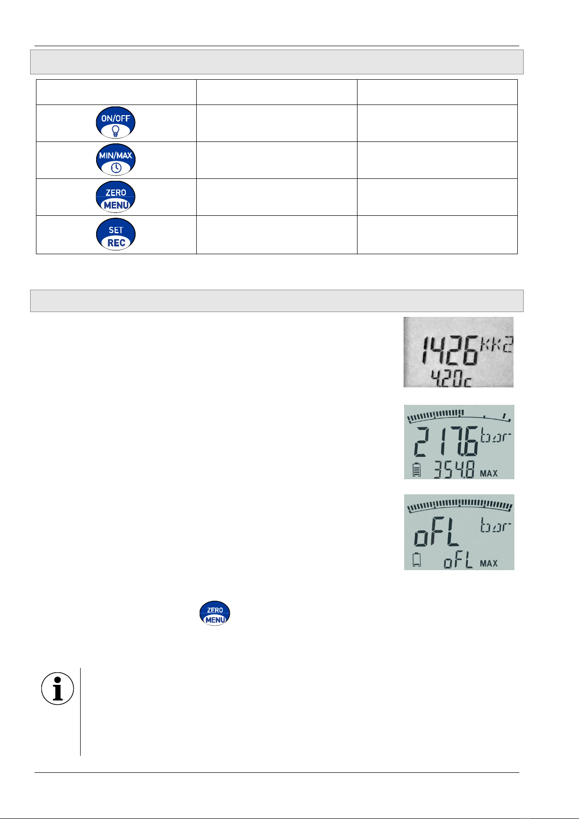
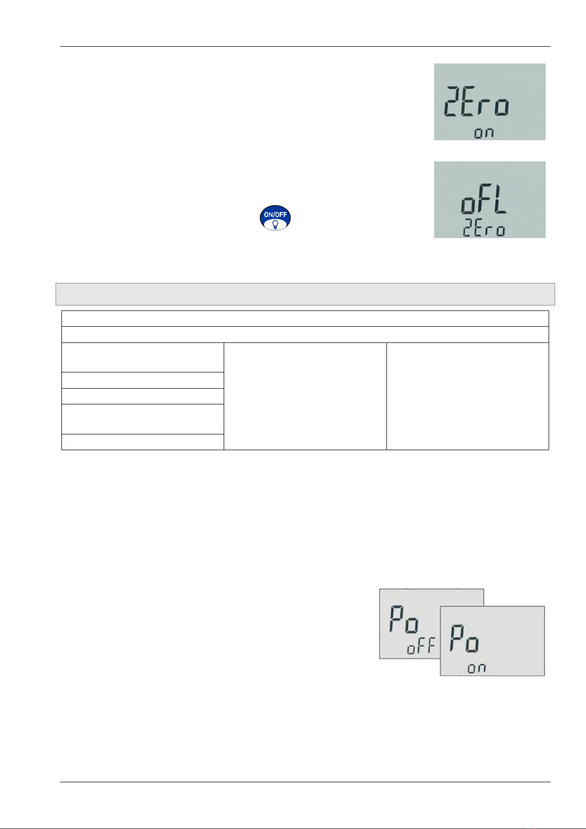
Press the ZERO/MENU button.
2Ero on appears in the display for 2 s. The ZERO function can
be activated.
Press the SET/OK button to perform the zero point correction.
The display and the MIN/MAX values are reset.
or
oFL 2Ero appears in the display for 2 s. The measured pres-
sure (0 bar) is greater than 5% of the pressure range. The ZERO
function cannot be performed.
The device switches back to measuring mode.
Depressurise and press the ZERO/MENU button again.
Resetting the zero point correction
The zero point correction stays activated until the device is switched
off. After it is switched on again, the zero point correction is no longer activated.
5.2 Device Settings
Press the ZERO/MENU button for 2 s.
Press ZERO/MENU button to continue.
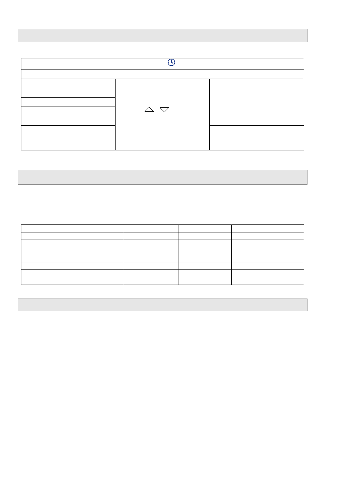
Automatic shut-off
(
Po off
/
Po on
)
Press the ZERO/MENU
button for the next menu item.
Confirm your selection with
the SET/REC button. You
return to the display mode.
Measuring unit (
unit
)
Display filter (
Filt
)*
Delete all measured data**
(dEL dAtA)
Device information
* Value selection: 0...7 (0 = no damping)
** Only version with data logger
You will automatically return to the display mode if you do not press any button for about 5 s.
Automatic shut-off
When the function is activated, the device automatically switches off after 5 minutes.
The automatic shut-off is deactivated for devices with data logger during data recording.
If the function is deactivated, the device is in continuous duty and has to be manually
switched off with the ON/OFF button.
The current setting is displayed when the digital pressure
gauge is switched on:
Po on = activated (automatic shut-off);
Po off = deactivated (continuous duty).
The settings Po on or Po off remain stored and are ac-
tive again when the device is switched on.

Data Logger E2 / D2 / C2
-28 - Ba_Ref-E2D2C2 • 09/2022
5.3 Setting the Date and Time
Only version with data logger:
Press the MIN/MAX/ button for 2 s.
Press the SET/REC button to continue.
Year (
4ear
)
Press / to set the
value.
Confirm with the SET/REC
button.
Month (
Mntx
)
Day (
da4
)
Hour (
Xour
)
Minute (
Min
)
Decimal separator*
(C0mma /P0int 5i9n)
Confirm with the SET/REC
button. You return to the dis-
play mode.
* Depending on the region, different decimal separators are used for the measured values.
6 Data Logger
Only version with data logger:
With the data logger function you can save up to 10 recording series. The longest recording
duration is 48 h. The storage rate adapts automatically within the recording duration. You can
transfer the measurement data in CSV format to your computer via the USB interface.
Recording duration
Max. time span
Storage rate
Max. data sets
0 s–1,800 s (0.5 h)
0.5 h (1,800 s)
100 ms
18,000
1,800 s–3,600 s (0.5 h–1 h)
1 h (3,600 s)
200 ms
18,000
1 h–2 h
2 h (7,200 s)
400 ms
18,000
2 h–4 h
4 h (14,400 s)
800 ms
18,000
4 h–8 h
8 h (28,800 s)
1,600 ms
18,000
8 h–16 h
16 h (57,600 s)
3,200 ms
18,000
16 h–48 h
48 h (172,800 s)
6,400 ms
27,000
6.1 Start or Stop Data Logger
Start data logger
Press the SET/REC button for 2 s.
REC flashes on the display. The number (1-10) of the recording series is also displayed.
Stop data logger
Press the SET/REC button for 2 s.
The data is saved and you return to the display mode.

E2 / D2 / C2 Maintenance and Return Shipment
Technical changes reserved - 29 -
6.2 Transfer and Delete Measured Data
Transfer measured data
Connect the digital pressure gauge to your computer with the USB cable supplied.
Switch on the digital pressure gauge if necessary.
The display shows Pc u5B. The digital pressure gauge is integrated as a removable data
carrier. You can access the measured data via your computer.
The measured data contains the time, MIN/MAX and ACTUAL values separated by a semi-
colon. If the measured data is displayed incorrectly, import the data as “text”.
Delete measured data
You can either delete all measured data via the device settings (dEL dAtA) or delete individ-
ual measurement data via the file manager of your operating system.
7 Maintenance and Return Shipment
IMPORTANT
Important parts or components can be damaged if the customer modifies or inter-
feres with the device.
The interference voids any warranty and manufacturer's responsibility!
Maintenance
The device is maintenance-free and cannot be repaired by the user. In case of a defect, the
device must be replaced or returned to the manufacturer for repair.
Only the batteries need to be changed regularly. We recommend replacing them with new
ones after 1.5 years at the latest (p. 25).
IMPORTANT
If the device is not used for a longer period, the batteries should be removed from
the device to prevent leakage damage.
Return shipment
Contact your supplier of the product for return shipment instructions.

Disassembly and Disposal E2 / D2 / C2
-30 - Ba_Ref-E2D2C2 • 09/2022
8 Disassembly and Disposal
CAUTION
Never remove the device from a plant in operation.
Make sure that the plant is shut down professionally.
Before disassembly
Prior to disassembly, ensure that the plant
is switched off.
is in a safe and de-energised state.
is depressurised and has cooled down.
Disassembly
Watch out for any leaking media. Take appropriate precautions to collect them
Loosen the pressure connection with an open-end wrench (AF 27).
Manually turn the digital pressure gauge out of the measurement setup.
Disposal
Compliant with the Directives 2011/65/EU (RoHS) and 2012/19/EU (WEEE)*, the device
must be disposed of separately as electrical and electronic waste.
NO HOUSEHOLD WASTE
The device consists of various different materials. It must not be disposed of with
household waste.
Take the device to your local recycling plant
or
send the device back to your supplier or to SIKA.
* WEEE reg. no.: DE 25976360

E2 / D2 / C2 Technical Data
Technical changes reserved - 31 -
9 Technical Data
The technical data of customised versions may differ from the data in these instructions.
Please observe the information specified on the type plate.
E2 / D2 / C2
Pressure ranges input
- Piezo resistive pressure cell
- Strain gauge pressure cell -1…3/5 bar (E2) and -1…3/5/10 bar (D2 / C2)
-1…10 (E2), -1…20/40/60 bar and
0…100/160/250/400/700/1000 bar
Accuracy (25°C)
±(% of full scale pressure value)(FS)
- Type E2
- Type D2
- Type C2
0.5 %
0.1 %
0.05 % (0.1 % in vacuum)
Sampling rate
10 ms (100 measurements/s)
Internal resolution AD converter
12 bit = 4,096 steps
Temperature influence
- Piezo resistive pressure cell
- Strain gauge pressure cell
0.05 % FS / K
0.005 % FS / K
Display
- Actual value
- MIN/MAX or Full Scale(FS)
- Bar graph
•Sampling rate
- Backlight
4 ½ digits (15 mm)
4 ½ digits (8 mm)
33 segments (drag indicator function)
50 ms (20 measurements/s)
50 x 34 mm
Pressure units
bar, PSI, mbar, kPa, MPa, kg/cm2, mH2O, inchH2O
Electrical characteristics
Supply voltage
Battery 2 x1.5 VDC AA (LR6 –AA), Alkaline (Mignon)
Battery life
1,500 h (without lighting)
Degree of protection (EN 60529)
IP 67
Data logger (optional)
Max. data sets per recording series
27,000
Recording series
1…10
Storage rate
0.1 s...6.4 s
automatically per recording duration
Max. recording duration
48 h
Data set information
Date / time
Time / ACTUAL pressure / Min / Max
Interface
1x Mini USB port
Software required
No – detection as removable data carrier
Data format
CSV

Technical Data E2 / D2 / C2
-32 - Ba_Ref-E2D2C2 • 09/2022
E2 / D2 / C2
Ambient conditions and process variables
Operating temperature
0…50 °C
Media temperature
-20…+80 °C
Storage temperature
-20…+60 °C
Relative humidity
< 85%
Vibration (IEC 60068-2-6)
10…500 Hz / 5 g
Shock (IEC 60068-2-29)
11 ms / 25 g
Pressure connection:
- Material
- Connection thread (ISO 1179-2)
- Gasket
Stainless steel 1.4404
G¼″
NBR
Housing:
- Material
- Dimensions (without cap)
- Dimensions (with cap)
Zinc cast (Rubber protection cap: TPE)
Ø = 79 mm, T = 33 mm
Ø = 90 mm, T = 45 mm
Weight
540 g
Display resolution
Pressure range
bar
PSI
mbar
kPa
-1...3 bar
-.999….3.000
-9.99…43.51
-999…3000
-99.9…300.0
-1...5 bar
-.999….5.000
-9.99…72.52
-999…5000
-99.9…500.0
-1...10 bar
-.999….10.000
-9.99…145.04
-999…10000
-99.9…1000.0
-1...20 bar
-.999….19.999
-14.5…290.1
-999…19999
-99.9…1999.9
-1...40 bar
-1.00….40.00
-14.5…580.2
-/-
-100…4000
-1...60 bar
-1.00….60.00
-14.5…870.2
-/-
-100…6000
0...100 bar
0.00…100.00
0…1450.4
-/-
0…10000
0...160 bar
0.00…160.00
0…2321
-/-
0…16000
0...250 bar
0.0…250.0
0…3626
-/-
-/-
0...400 bar
0.0…..400.0
0…5802
-/-
-/-
0...700 bar
0.0…..700.0
0…10153
-/-
-/-
0...1000 bar
0.0…1000.0
0…14504
-/-
-/-
Pressure range
MPa
kg/cm2
mH2O
inH2O
-1...3 bar
-.100…0.300
-.999…3.059
-9.99…30.59
-99.9…1204.4
-1...5 bar
-.100…0.500
-.999…5.099
-9.99…50.99
-99.9…1999.9
-1...10 bar
-.100…1.000
-.999…10.197
-9.99…101.97
-401…4015
-1...20 bar
-.100…2.000
-.999…19.999
-9.99…199.99
-401…8029
-1...40 bar
-.100…4.000
-1.02…40.79
-10.2…407.9
-401…16059
-1...60 bar
-.100…6.000
-1.02…61.18
-10.2…611.9
-/-
0...100 bar
0.000…10.000
0.00…101.97
0.0…1019.7
-/-
0...160 bar
0.000…16.000
0.00…163.15
0.0…1631.6
-/-
0...250 bar
0.000…25.00
0.0…254.9
0…2549
-/-
0...400 bar
0.000…40.00
0.0…407.9
0…4079
-/-
0...700 bar
0.000…70.00
0.0…713.8
0…7138
-/-
0...1000 bar
0.000…100.00
0.0…1019.7
0…10197
-/-

E2 / D2 / C2 Technical Data
Technical changes reserved - 33 -
WARNING
Exceeding the maximum overload values (Pmax) can lead to malfunctions and
result in the digital pressure gauge being destroyed.
Overload values
Pressure range
Overload
Burst pressure
-1...3 bar
12 bar
20 bar
-1...5 bar
18 bar
30 bar
-1...10 bar
30 bar
50 bar
-1...20 bar
50 bar (E2)
48 bar (D2 / C2)
250 bar (E2)
80 bar (D2 / C2)
-1...40 bar
80 bar
400 bar
-1...60 bar
120 bar
550 bar
0...100 bar
200 bar
800 bar
0...160 bar
320 bar
1000 bar
0...250 bar
500 bar
1200 bar
0...400 bar
800 bar
1700 bar
0...700 bar
1200 bar
2400 bar
0...1000 bar
1500 bar
2500 bar
At 0 bar relative, the following threshold values must be exceeded for a measured value to be
displayed:
Threshold
values
Type E2 Type D2 / C2
Pressure range
Threshold value
[bar]
Resolution
[bar]
Threshold value
[bar]
Resolution
[bar]
-1...3 bar
0.006
0.002
0.003
0.002
-1...5 bar
0.010
0.002
0.005
0.002
-1...10 bar
0.020
0.003
0.01
0.003
-1...20 bar
0.04
0.01
0.02
0.01
-1...40 bar
0.08
0.01
0.04
0.01
-1...60 bar
0.12
0.02
0.06
0.02
0...100 bar
0.20
0.03
0.1
0.03
0...160 bar
0.32
0.04
0.16
0.04
0...250 bar
0.5
0.1
0.3
0.1
0...400 bar
0.8
0.1
0.4
0.1
0...700 bar
1.4
0.2
0.7
0.2
0...1000 bar
2.0
0.3
1.0
0.3

Technical Data E2 / D2 / C2
-34 - Ba_Ref-E2D2C2 • 09/2022
9.1 Dimensions
Strain gauge pressure cell without data logger
Strain gauge pressure cell with data logger

E2 / D2 / C2 Technical Data
Technical changes reserved - 35 -
Piezo resistive pressure cell without data logger
Piezo resistive pressure cell with data logger

EU Declaration of Conformity E2 / D2 / C2
10 EU Declaration of Conformity
The digital pressure gauges types E2 / D2 / C2 comply with the 2014/30/EU, 2014/68/EU and
2011/65/EU directives.
The types E2 / D2 / C2 comply with the technical regulations DIN EN 61000-6-2 + rectifica-
tion 1:2011, DIN EN 61000-6-3:2007 + rectification 1:2011 and DIN EN 50581:2013.
Cert. 00007
Hydrotechnik UK Test Engineering Ltd, 1 Central Park, Lenton Lane, Nottingham, NG7 2NR, UK
This manual suits for next models
6
Table of contents
Other Hydrotechnik Measuring Instrument manuals

Hydrotechnik
Hydrotechnik MultiControl 4070 User manual

Hydrotechnik
Hydrotechnik MultiSystem 4010 User manual

Hydrotechnik
Hydrotechnik MultiSystem 5070 User manual

Hydrotechnik
Hydrotechnik MultiSystem 5060 User manual

Hydrotechnik
Hydrotechnik Patrick in the Box User manual

Hydrotechnik
Hydrotechnik MultiSystem 4070 User manual

Hydrotechnik
Hydrotechnik NCTE User manual

Hydrotechnik
Hydrotechnik MultiSystem 5060 User manual

Hydrotechnik
Hydrotechnik Patrick User manual

Hydrotechnik
Hydrotechnik SEG 1060 User manual