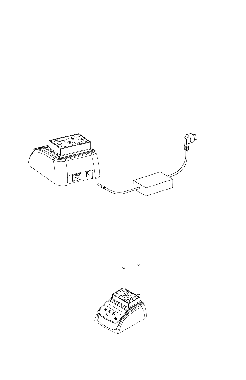
Hygiena INCUBATOR User manual

INCUBATOR
Operations Manual
Version 1.0
Hygiena
941 Avenida Acaso
Camarillo, CA 93012
805-388-8007

Packing List
No
. Item Type QTY
1 Incubator INCUBATOR 1
2 Adapter 12V 4A 1
3 Wrench 1
4 Operations manual 1
5 Certification 1
12
Foreword
Thank you for purchasing our Products: INCUBATOR, This
Manual for users contains function and operation of the Inst
rument. In order to use the instrument properly, please read
this manual carefully before using the Instrument.
Opening Check
Please check the Instrument and Appendix with the packing
list when you first open the instrument packing case. If you
find there is something wrong with the Instrument and the
Appendix, do contact the vendor or the producer.

Annex 1 Wiring Diagram for Incubator
11
100-240V~
Adapter
12V 4A Mains switch
Sensor Heater
Display
Main
board
J8 J10
J3 J4
J1
panel
J2
Contents
1. Introduction………………………………………………......1
1.1 Delivery package…………………………….…………….1
1.2 Structure Description………………………………….......2
1.3 Installing the device………………………………….…....3
2. Technical data……………………………………………….4
3. Safety precautions……………..……………………….......5
4. Operation guide..…………………………………………….6
4.1 Control elements……….…………………………………..6
4.2 Create a new program……... ..…………………………...6
4.3 Min or Sec….…….………………………………..…….....6
4.4 Run and Stop…………………………………………….…7
4.5 Temperature calibration…………………………………..8
5.Maintenance and cleaning…………………………………10
6. Troubleshooting……………………………......................10
Annex 1 Wiring Diagram for Incubator …………………...11
Packing list…………………………………………………..12

1 Introduction
This Incubator designed for workstations in training and rese
arch laboratories in the fields of bioscience, medicine and ch
emistry.
Before starting up this incubator for the first time, please rea
d the rest of this operations manual.
1.1 Delivery package
Incubator 1pcs
Adapter 1pcs
Wrench 1pcs
Operations manual 1pcs
Certification 1pcs
1
5 Maintenance and cleaning
The well in the block should be cleaned by the cloth stained
with alcohol to assure good heat translation between the bl
ock and the test tube and no pollution. If there are smutche
s on the Instrument, clean them with cloth.
Power off when cleaning the Instrument.
When cleaning the well, don’t drop the cleaning liquid in th
e well.
Corrosive cleaning liquid is strongly prohibited.
6 Troubleshooting
Error Cause Solution
No display
No main power
connection.
Power failure.
Plug in mains cable
on both sides.
Check the mains fuse
“OPEN” in the
display with the
alarm of “du...”
Broken sensor
or loose
contact of the
module
Contact service.
“SHO” in the
display with the
alarm of “du...”
The sensor is
short Contact service.
No heating of
the block Heater failure Contact service.
Press invalid Keyboard
failure Contact service.
10

40.0Adj
4.5.3 Pressing “”and“” key simultaneously,
practical temperature shows 20.5, and rise to 40.0
at once, at the same time the sign “*” flicker
ceaselessly. When the practical temperature reach
40.0, the sign “ADJ” and “*” flicker ceaselessly
together.
Press “start”
4.5.4 After 20 mintues, the actual temperature of
Thermometer is 38.8℃, then pressing “”or
“”key to amend the display value to
38.8, then pressing “start” key to confirm.
38.8Adj
Then rise to 80.0℃automatically and “*”
flicker ceaselessly.
4.5.5 When the practical temperature reach
80.0,
the sign “ADJ” and “*” flicker ceaselessly
together.
80.0Adj
4.5.6 After 20 mintues,the actual temperature of
Thermometer is 79.0℃. pressing “”or “”key to
amend the display value to 79.0, then pressing
“start” key to confirm.
79.0Adj
“”
“”
Press “start”
4.5.7 Then the screen returns to the
display as the right chart. P1 74.5 ℃NOTOK
After Temperature calibration, the temperature displayed is the
same with the practical temperature of block.
Note! During Temperature calibration, press “”and“”key
simultaneously to cancel the calibration. The system keeps the former
calibration.
So don’t press “”and “”key simultaneously unless need
calibrate the temperature!
9
1.2 Structure Description
2
Display
Panel
Power Switch
Power connector
Block

1.3 Installing the device
1.3.1 Place the incubator onto a level , horizontal surface.
1.3.2 Insert the column connector of the adapter to power connector
of the device ,and insert another connector of the adapter to mains p
ower supply.
1.3.3 Power on the main switch. The incubator is ready to operate
when the display becomes visible.
1.3.4 Put the test tube into the block.
3
100-240V~
DC 12V
Tube
4.5 Temperature calibration
The temperature of the instrument has been calibrated before it is sold
out. But if there is deviation between the actual temperature and the
displayed temperature due to some reasons, you can do as follows to
correct the error.
Notes: The Instrument uses double temperatures adjustment to ensure
its veracity. This means it is linearly calibrated on 40℃and 80℃two
points. The temperature veracity will be within ±0.5℃after the double
temperature adjustment.
The circumstances should be lower than 35℃.
Adjustment methods as follows:
4.5.1 After the startup of the Instrument, it enters waiting interface. Make
sure the temperature in display is below 35℃. If the temperature is
higher than 35℃, you should wait until the temperature is below 35℃.
4.5.2 Inject olefin oil into one of the cone-shaped wells, and then put a
thermometer into this well (Make sure the precision of the thermometer
should be within 0.1℃and the temperature ball should be absolutely
immerged into the cone-shaped well). Seeing from Fig a.
8
Note! The temperature can be corrected only after the instrument
reaches the set temperature for 20 minutes to ensure the precise
of the temperature.
Fig a Thermometer
Mineral oil
cone-shaped well

7
4.4 Run and Stop
4.4.1 Press “PROG.” key to select the program.
4.4.2 The instrument start to heat automatically according to the previ
ous set temperature, it shows “NOTOK” at the display. When it reach t
he target temperature, it shows “OK” at the display. Then pressing the
START/STOP key to run,
4.4.4 Press “START/STOP” key for 1 seconds continuously to stop
the program.
P8 35.5 ℃NOTOK
4.4.3 When the second time reach 0, the buzzer alarm “du. du. du…
….” and the display appear PROGRAM END. The controller hold the
second temperature. Pressing any key to return, and pressing the
START key to run again.
Pressing any key
When the first temperature over ,it will run second temperature autom
-atically.
PROGRAM END
P8 45.0 ℃OK
Press START to run again
P8 45.0 ℃OK
P8 45.0 020min P8 45.0 020min
2 Technical data
Model INCUBATOR
Power supply DC12V
Power 35 W
Temperature range RT+5 ℃~80 ℃
Timing range 1sec ~999sec or
1min ~999min
Accuracy of the
temperature ≤±0.5℃
Display accuracy 0.1℃
Heating time
(from 20 ℃to 80 ℃) ≤12min
Ambient temperature 5℃~35℃
Dimensions(W×D×H)110mm×150mm×80mm
Weight 0.5 kg
4

3 Safety precautions
This product is a normal and an indoor Instrument.
5
Read the Manual carefully before operation, The expert o
f wiring equipment can operate this Instrument.
The operator should not open or repair the Instrument by hi
mself, which will result in losing the qualification of repair gu
arantee or occur accident. If there is some wrong with the In
strument, the company will repair it.
The Instrument should be put in the place of low temperatur
e, little dust, no water and no sun or strong lamp. What’s mo
re, the place should be good aeration, no corrosively gas or
strong disturbing magnetic field, far away from central heatin
g, camp stove and other hot resource. Don't put the Instrum
ent in wet and dusty place.
Mains switch is on the rear of the device, push “I” to
power on the device, and push “O” to power off the
device.
Power off when you finish your work. Pull off the connector plu
g when there’s long time no use of the Instrument and cover it
with a cloth or plastic paper to prevent from dust.
Power connector is on the rear of the
device, DC12V input, inside is “+” , Out
side is “-”.
4. Operation guide
4.1 Control elements
START/STOP----for start or stop the procedure
PROG.-------------select various programs
----------------for setting the temperature and the time
----------------remove the cursor
4.2 Create a new program
press “PROG.” key to select various programs, from P1 to P9
default. If select P8,then press key to remove the cursor ,press
key to set new value, we can set, first temperature ,first timing
time ,second temperature and second timing time . The sign “ ” is
first temperature and first time ,the sign “ ” is second temperature
and second time.
6
P8 50.0 003min First temperature and time
Second temperature and time
P8 40.0 006min
4.3 Min or sec
At setting interface ,the timer unit can select one of the Minute or
Second. Press key for 2 seconds continuously.
Timer unit : sec
Timer unit : min
Then press to select min or sec, then press key to confirm.
P8 36.2 ℃NOTOK
About 8 seconds, the curse will disappear, exit setting interface.
show room temperature

7
4.4 Run and Stop
4.4.1 Press “PROG.” key to select the program.
4.4.2 The instrument start to heat automatically according to the previ
ous set temperature, it shows “NOTOK” at the display. When it reach t
he target temperature, it shows “OK” at the display. Then pressing the
START/STOP key to run,
4.4.4 Press “START/STOP” key for 1 seconds continuously to stop
the program.
P8 35.5 ℃NOTOK
4.4.3 When the second time reach 0, the buzzer alarm “du. du. du…
….” and the display appear PROGRAM END. The controller hold the
second temperature. Pressing any key to return, and pressing the
START key to run again.
Pressing any key
When the first temperature over ,it will run second temperature autom
-atically.
PROGRAM END
P8 45.0 ℃OK
Press START to run again
P8 45.0 ℃OK
P8 45.0 020min P8 45.0 020min
2 Technical data
Model INCUBATOR
Power supply DC12V
Power 35 W
Temperature range RT+5 ℃~80 ℃
Timing range 1sec ~999sec or
1min ~999min
Accuracy of the
temperature ≤±0.5℃
Display accuracy 0.1℃
Heating time
(from 20 ℃to 80 ℃) ≤12min
Ambient temperature 5℃~35℃
Dimensions(W×D×H)110mm×150mm×80mm
Weight 0.5 kg
4

1.3 Installing the device
1.3.1 Place the incubator onto a level , horizontal surface.
1.3.2 Insert the column connector of the adapter to power connector
of the device ,and insert another connector of the adapter to mains p
ower supply.
1.3.3 Power on the main switch. The incubator is ready to operate
when the display becomes visible.
1.3.4 Put the test tube into the block.
3
100-240V~
DC 12V
Tube
4.5 Temperature calibration
The temperature of the instrument has been calibrated before it is sold
out. But if there is deviation between the actual temperature and the
displayed temperature due to some reasons, you can do as follows to
correct the error.
Notes: The Instrument uses double temperatures adjustment to ensure
its veracity. This means it is linearly calibrated on 40℃and 80℃two
points. The temperature veracity will be within ±0.5℃after the double
temperature adjustment.
The circumstances should be lower than 35℃.
Adjustment methods as follows:
4.5.1 After the startup of the Instrument, it enters waiting interface. Make
sure the temperature in display is below 35℃. If the temperature is
higher than 35℃, you should wait until the temperature is below 35℃.
4.5.2 Inject olefin oil into one of the cone-shaped wells, and then put a
thermometer into this well (Make sure the precision of the thermometer
should be within 0.1℃and the temperature ball should be absolutely
immerged into the cone-shaped well). Seeing from Fig a.
8
Note! The temperature can be corrected only after the instrument
reaches the set temperature for 20 minutes to ensure the precise
of the temperature.
Fig a Thermometer
Mineral oil
cone-shaped well

40.0Adj
4.5.3 Pressing “”and“” key simultaneously,
practical temperature shows 20.5, and rise to 40.0
at once, at the same time the sign “*” flicker
ceaselessly. When the practical temperature reach
40.0, the sign “ADJ” and “*” flicker ceaselessly
together.
Press “start”
4.5.4 After 20 mintues, the actual temperature of
Thermometer is 38.8℃, then pressing “”or
“”key to amend the display value to
38.8, then pressing “start” key to confirm.
38.8Adj
Then rise to 80.0℃automatically and “*”
flicker ceaselessly.
4.5.5 When the practical temperature reach
80.0,
the sign “ADJ” and “*” flicker ceaselessly
together.
80.0Adj
4.5.6 After 20 mintues,the actual temperature of
Thermometer is 79.0℃. pressing “”or “”key to
amend the display value to 79.0, then pressing
“start” key to confirm.
79.0Adj
“”
“”
Press “start”
4.5.7 Then the screen returns to the
display as the right chart. P1 74.5 ℃NOTOK
After Temperature calibration, the temperature displayed is the
same with the practical temperature of block.
Note! During Temperature calibration, press “”and“”key
simultaneously to cancel the calibration. The system keeps the former
calibration.
So don’t press “”and “”key simultaneously unless need
calibrate the temperature!
9
1.2 Structure Description
2
Display
Panel
Power Switch
Power connector
Block

1 Introduction
This Incubator designed for workstations in training and rese
arch laboratories in the fields of bioscience, medicine and ch
emistry.
Before starting up this incubator for the first time, please rea
d the rest of this operations manual.
1.1 Delivery package
Incubator 1pcs
Adapter 1pcs
Wrench 1pcs
Operations manual 1pcs
Certification 1pcs
1
5 Maintenance and cleaning
The well in the block should be cleaned by the cloth stained
with alcohol to assure good heat translation between the bl
ock and the test tube and no pollution. If there are smutche
s on the Instrument, clean them with cloth.
Power off when cleaning the Instrument.
When cleaning the well, don’t drop the cleaning liquid in th
e well.
Corrosive cleaning liquid is strongly prohibited.
6 Troubleshooting
Error Cause Solution
No display
No main power
connection.
Power failure.
Plug in mains cable
on both sides.
Check the mains fuse
“OPEN” in the
display with the
alarm of “du...”
Broken sensor
or loose
contact of the
module
Contact service.
“SHO” in the
display with the
alarm of “du...”
The sensor is
short Contact service.
No heating of
the block Heater failure Contact service.
Press invalid Keyboard
failure Contact service.
10

Annex 1 Wiring Diagram for Incubator
11
100-240V~
Adapter
12V 4A Mains switch
Sensor Heater
Display
Main
board
J8 J10
J3 J4
J1
panel
J2
Contents
1. Introduction………………………………………………......1
1.1 Delivery package…………………………….…………….1
1.2 Structure Description………………………………….......2
1.3 Installing the device………………………………….…....3
2. Technical data……………………………………………….4
3. Safety precautions……………..……………………….......5
4. Operation guide..…………………………………………….6
4.1 Control elements……….…………………………………..6
4.2 Create a new program……... ..…………………………...6
4.3 Min or Sec….…….………………………………..…….....6
4.4 Run and Stop…………………………………………….…7
4.5 Temperature calibration…………………………………..8
5.Maintenance and cleaning…………………………………10
6. Troubleshooting……………………………......................10
Annex 1 Wiring Diagram for Incubator …………………...11
Packing list…………………………………………………..12

Packing List
No
. Item Type QTY
1 Incubator INCUBATOR 1
2 Adapter 12V 4A 1
3 Wrench 1
4 Operations manual 1
5 Certification 1
12
Foreword
Thank you for purchasing our Products: INCUBATOR, This
Manual for users contains function and operation of the Inst
rument. In order to use the instrument properly, please read
this manual carefully before using the Instrument.
Opening Check
Please check the Instrument and Appendix with the packing
list when you first open the instrument packing case. If you
find there is something wrong with the Instrument and the
Appendix, do contact the vendor or the producer.

INCUBATOR
Operations Manual
Version 1.0
Hygiena
941 Avenida Acaso
Camarillo, CA 93012
805-388-8007
Other manuals for INCUBATOR
1
Table of contents
Other Hygiena Laboratory Equipment manuals

Hygiena
Hygiena Innovate Installation manual

Hygiena
Hygiena foodproof KIT230127 User manual

Hygiena
Hygiena SuperSnap SUS3000X User manual

Hygiena
Hygiena BAX Q7 User manual

Hygiena
Hygiena EnSURE Touch User manual

Hygiena
Hygiena UltraSnap US2020 User manual

Hygiena
Hygiena Dualo 32 R2 Instruction sheet

Hygiena
Hygiena RiboPrinter User manual

Hygiena
Hygiena DUP-1000 User manual

Hygiena
Hygiena BAX System Q7 Instruction Manual