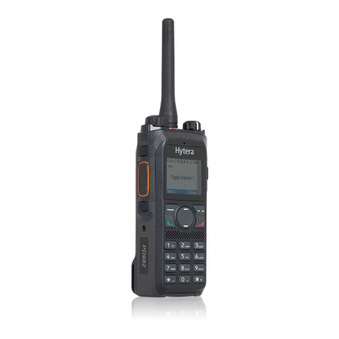
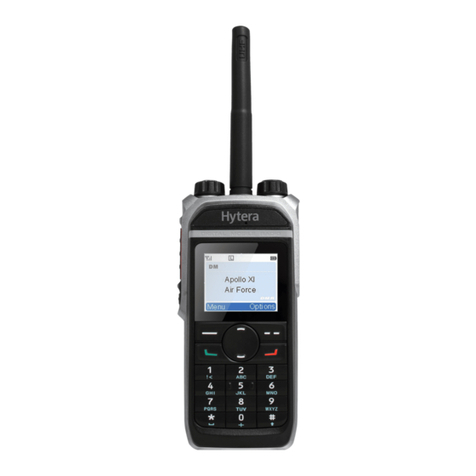
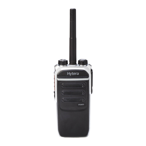
Hytera PD60 UL913 Series User manual

DIGITAL PORTABLE RADIO
PD60X UL913 USER MANUAL

Welcome to the world of Hytera and thank you for purchasing this product. This manual
includes a description of the functions and step-by-step procedures for use. It also includes
a troubleshooting guide. To avoid bodily injury or property loss caused by incorrect
operation, please carefully read the Safety Information Booklet before use.
This manual is applicable to the following product:
PD60X Digital Portable Radio (X may represent 2, 5, 6 or 8)

Copyright Information
Hytera is the trademark or registered trademark of Hytera Communications
Corporation Limited (the Company) in the People's Republic of China (PRC)
and/or other countries or areas. The Company retains the ownership of its
trademarks and product names. All other trademarks and/or product names
that may be used in this manual are properties of their respective owners.
The product described in this manual may include the Company's computer
programs stored in memory or other media. Laws in PRC and/or other
countries or areas protect the exclusive rights of the Company with respect
to its computer programs. The purchase of this product shall not be deemed
to grant, either directly or by implication, any rights to the purchaser
regarding the Company's computer programs. The Company's computer
programs may not be copied, modified, distributed, decompiled, or reverse-
engineered in any manner without the prior written consent of the Company.
Disclaimer
The Company endeavors to achieve the accuracy and completeness of this
manual, but no warranty of accuracy or reliability is given. All the
specifications and designs are subject to change without notice due to
continuous technological development. No part of this manual may be
copied, modified, translated, or distributed in any manner without the prior
written consent of the Company.
We do not guarantee, for any particular purpose, the accuracy, validity,
timeliness, legitimacy or completeness of the third- party products and
contents involved in this manual.
If you have any suggestions or would like to receive more information,
please visit our website at: http://www.hytera.com.
FCC Statement
This equipment has been tested and found to comply with the limits for a
Class B digital device, pursuant to part 15 of FCC Rules. These limits are
designed to provide reasonable protection against harmful interference in a
residential installation. This equipment generates and can radiate radio
frequency energy. If not installed and used in accordance with the
instructions, it may cause harmful interference to radio communications.
However, there is no guarantee that interference will not occur in a
particular installation. Verification of harmful interference by this
equipment to radio or television reception can be determined by turning it
off and then on. The user is encouraged to try to correct the interference by
one or more of the following measures:
lReorient or relocate the receiving antenna. Increase the separation
between the equipment and receiver.
lConnect the equipment into an outlet on a different circuit to that of the
receiver's outlet.
lConsult the dealer or an experienced radio/TV technician for help.

Operation is subject to the following two conditions:
lThis device may not cause harmful interference.
lThis device must accept any interference received, including
interference that may cause undesired operation.
Note: Changes or modifications to this unit not expressly approved by the
party responsible for compliance could void the user's authority to operate
the equipment.
Compliance with RF Exposure Standards
The radio complies with the following RF energy exposure standards and
guidelines:
lUnited States Federal Communications Commission, Code of Federal
Regulations; 47 CFR § 1.1307, 1.1310 and 2.1093
lAmerican National Standards Institute (ANSI)/Institute of Electrical and
Electronic Engineers (IEEE) C95. 1:2005; Canada RSS102 Issue 5
March 2015
lInstitute of Electrical and Electronic Engineers (IEEE) C95.1:2005
Edition
RF Exposure Compliance and Control
Guidelines and Operating Instructions
To control your exposure and ensure compliance with the
occupational/controlled environmental exposure limits, always adhere to the
following procedures.
Guidelines:
lDo not remove the RF Exposure Label from the device.
lUser awareness instructions should accompany device when
transferred to other users.
lDo not use this device if the operational requirements described herein
are not met.
Operating Instructions:
lTransmit no more than the rated duty factor of 50% of the time. To
transmit (talk), press the Push-to-Talk (PTT) key. To receive calls,
release the PTT key. Transmitting 50% of the time, or less, is important
because the radio generates measurable RF energy only when
transmitting (in terms of measuring for standards compliance).
lKeep the radio unit at least 2.5 cm away from the face. Keeping the
radio at the proper distance is important as RF exposure decreases with
distance from the antenna. The antenna should be kept away from the
face and eyes.
lWhen worn on the body, always place the radio in an approved holder,
holster, case, or body harness or by use of the correct clip for this
product. Use of non-approved accessories may result in exposure levels

which exceed the FCC's occupational/controlled environmental RF
exposure limits.
lUse of non-approved antennas, batteries, and accessories causes the
radio to exceed the FCC RF exposure guidelines.
lContact your local dealer for the product's optional accessories.
EU Regulatory Conformance
As certified by the qualified laboratory, the product is in compliance with
the essential requirements and other relevant provisions of 2014/53/EU.
Please note that the above information is applicable to EU countries only.

Contents
Contents 1
Documentation Information 3
Icon Conventions 3
Notation Conventions 3
Packing List 3
Product Overview 4
Product Layout 4
Programmable Key 4
LED Indications 4
Before Use 5
Charging the Battery 5
Attaching the Battery 5
Attaching the Antenna 6
Attaching the Belt Clip 6
Attaching the Audio Accessory 6
Basic Operations 7
Turning the Radio On or Off 7
Adjusting the Volume 7
Checking the Battery Power 7
Switching the Operation Mode 7
Selecting a Zone and Channel 7
Call Services 8
Call on Digital Channel 8
Call on Analog Channel (Conventional Only) 10
Supplementary Features 10
Basic Settings 12
Audio Settings 15
One Touch Call 16
Scan 17
Hunt 17
Positioning 19
Personal Safety Services 20
Communication Security Services 22
1

Conventional Features 23
Trunking Features 26
Troubleshooting 28
Care and Cleaning 30
Product Care 30
Product Cleaning 30
Optional Accessories 30
Abbreviations 30
2

Documentation Information
Icon Conventions
Icon Description
Indicates references that can further describe the related
topics.
Indicates situations that could cause data loss or equipment
damage.
Notation Conventions
Item Description Example
Boldface
Denotes menus, tabs,
parameter names,
window names,
dialogue names, and
hardware buttons.
To save the configuration, click Apply.
The Log Level Settings dialogue
appears.
Press the PTT key.
" "
Denotes messages,
directories, file
names, folder names,
and parameter
values.
The screen displays "Invalid Battery!".
Open "PDT_PSS.exe".
Go to "D:/opt/local".
In the Port text box, enter "22".
>Directs you to access
a multi-level menu. Go to File >New.
Item Description Example
Italic Denotes document
titles.
For details about using the DWS, refer
to Dispatch Workstation User Guide.
Courier
New
Denotes commands
and their execution
results.
To set the IP address, run the following
command:
vos-cmd - m name IP
Packing List
Please unpack carefully and check that you have received the following
items. If any item is missing or damaged, contact your dealer.
Item Quantity (PCS) Item Quantity (PCS)
Radio 1 Antenna 1
Battery 1 Belt Clip 1
Charger 1 Strap 1
Power Adapter 1 Documentation Kit 1
lCheck whether the frequency band marked on the antenna label
matches that on the radio label. If not, contact your dealer.
lFigures in this manual are for reference only.
3

Product Overview
Product Layout
Programmable Key
You can request your dealer to program SK1 as a shortcut to a radio
feature. Consult your dealer for assignable radio features.
LED Indications
LED Indicator Radio Status
Flashes green The radio is being turned on.
Flashes green slowly The radio is standby in trunking mode.
Glows green The radio is receiving.
Glows red The radio is transmitting.
Flashes red The calling radio is establishing a call in trunking
mode.
Flashes orange slowly The radio is scanning, roaming or hunting.
Flashes orange rapidly
lConventional mode: The radio is operating in
emergency mode.
lTrunking mode: The called radio is
establishing a Full Off Air Call Set-Up
(FOACSU) call.
Glows orange
Call hang time: No voice is being transmitted or
received on the channel during a call. Within
such a period, you can press and hold the PTT
key and speak.
4

Before Use
Charging the Battery
lRead the Safety Information Booklet before charging.
lUse the approved charger to charge the battery.
lThe remaining lithium-ion battery power is limited to 30% pursuant
to the new lithium battery shipment regulation approved by
International Air Transport Association (IATA).
Before initial use, make sure to charge the battery. You can charge either
the standalone battery or the radio with battery attached. It is recommended
that the radio remain powered off during charging.
To charge the battery, do as follows:
1. Insert the output connector of the power adapter into the port on the
back of the charger.
2. Plug the power adapter into a power outlet.
3. Place the battery into the charger.
The LED indicator on the charger shows the charging status. For details, see
the following table:
LED Indicator Charging Status
Flashes red slowly No battery is placed on the charger.
Glows red The battery is being charged.
Glows orange The battery is charged to 90% or above.
Glows green The battery is fully charged.
Flashes red rapidly The battery fails to be charged.
Attaching the Battery
To remove the battery, make sure that the radio is turned off, and then
lift the battery latch.
5

Attaching the Antenna
Do not hold the radio by the antenna and swing it. This may affect the
antenna performance and shorten the life span of the antenna.
Attaching the Belt Clip
1. Use a screwdriver to remove the screws on the back of the radio.
2. Align the screw holes on the belt clip with those on the back of the
radio.
3. Put the screws back in place, and then use the screwdriver to tighten
them.
Attaching the Audio Accessory
For optimal waterproof and dustproof performance, do close the
accessory connector cover and fasten the screw when no accessory is
attached.
1. Loosen the screw on the accessory connector cover, and open the
cover.
2. Align the accessory plug with the accessory connector, and then tighten
the screw on the accessory plug.
6

Basic Operations
Turning the Radio On or Off
Adjusting the Volume
Checking the Battery Power
To check the battery power, press and hold the preprogrammed Battery
Power Indicator key. The following table lists the battery power
indications.
Switching the Operation Mode
The radio can operate in conventional or trunking mode if enabled by your
dealer.
To manually switch the operation mode, press the preprogrammed
Operation Mode Switch key.
To allow the radio to automatically switch to a mode based on signal
strength, press the preprogrammed Mode Auto Switch key.
Selecting a Zone and Channel
Conventional Mode
In conventional mode, the radio receives and transmits data and voice on the
selected channel. A zone is a group of channels within the same
7
LED Indicator Alert Tone Battery Power
Glows green Three beeps High
Glows orange Two beeps Medium
Glows red One beep Low
Flashes red Low battery
tone
Under the low battery threshold.
Recharge or replace the battery.

operational area. The radio supports up to 16 zones, each of which contains
up to 16 channels. Before selecting a channel, make sure that the current
zone contains the channel.
To select a zone, press the preprogrammed Zone Up or Zone Down key.
To select a channel, do one of the following:
lRotate the Channel Selector knob.
lPress the preprogrammed Channel Up or Channel Down key.
lPress the preprogrammed Preset Channel key to switch to the preset
channel.
If the Channel Notify feature is enabled, the radio automatically
announces the current channel upon power-on and channel change.
Trunking Mode
In trunking mode, the radio automatically hunts for available base stations.
After successful registration, the radio can receive and transmit data and
voice.
During hunting, the LED indicator flashes orange slowly with an alert tone.
To select a group contact or a private contact, do one of the following:
lRotate the Group Selector knob.
lPress the preprogrammed Group/Private Contact Up or
Group/Private Contact Down key.
A subgroup consists of multiple groups or private contacts.
To select a subgroup, press the preprogrammed Subgroup Up or Subgroup
Down key.
Call Services
When you are speaking during a call, keep the microphone about 2.5 to 5
cm away from your mouth. This ensures optimal voice quality on the
receiving radio.
In trunking mode, if the radio is not registered or attached, or an empty
group is selected, you cannot initiate a call.
Call on Digital Channel
You can initiate or receive the following types of calls on a digital channel:
lGroup call: a call from an individual user in a group to all the other
members in the group.
lPrivate call: a call from an individual user to another individual user.
lBroadcast call (enabled by your dealer): a special group call in the
trunking mode. During the call, only the calling party can speak.
8

lAll call (enabled by your dealer): In conventional mode, it is a call from
an individual user to all other users on the current channel. In trunking
mode, it is a call from an individual user to all other users in the
network; according to whether the called party can respond, an all call
is classified into the following two types:
» Broadcast all call: The called party cannot respond to the call.
» General all call: The called party can respond to the call.
In trunking mode, with the Auto Select Available Site feature enabled by
your dealer, the radio can register with an available BS where the current
group is not limited after powering on or during the current group/BS
changing.
Initiating a Call
Conventional Mode
lOn the home screen, rotate the Channel Selector knob to select the
required channel, and then press and hold the PTT key to initiate a call
to the contact preset on the channel.
lIf the One Touch Call feature is configured by your dealer, press the
preprogrammed One Touch Call key, and then press and hold the PTT
key to initiate a call.
Trunking Mode
If the radio is not registered or attached, or an empty group is selected, you
cannot initiate a call.
lOn the home screen, rotate the Group Selector knob to select the
required group or private contact, and then press the PTT key to initiate
a call.
lIf the One Touch Call feature is configured by your dealer, press the
preprogrammed One Touch Call key to initiate a call.
Receiving a Call
Conventional Mode
You can listen to an incoming private/group/broadcast/all call without any
operations.
Trunking Mode
You can listen to an incoming group/broadcast/all call without any
operations.
For an incoming private call, you can listen to it in different ways varying
with the setup mode of the call:
lWhen receiving an Off Air Call Set-Up (OACSU) private call, you can
listen to it without any operation.
9

lWhen receiving a FOACSU private call, press the PTT key to establish
the call.
Ending a Call
Conventional Mode
lA private/group call ends when the call hang time expires.
lAn all call ends when the calling party releases the PTT key.
Trunking Mode
lA call ends when the calling party hangs up or presses the
preprogrammed Clear Down key.
lA private call also ends when the called party hangs up or presses the
preprogrammed Clear Down key.
Call on Analog Channel (Conventional Only)
You can initiate or receive a call on an analog channel with or without
signaling.
Call Without Signaling
On an analog channel without signaling, you can initiate a call to all the
other users on the channel. Do as follows:
1. Rotate the Channel Selector knob to select the required channel.
2. Press and hold the PTT key, and then speak into the microphone.
Call With Signaling
On an analog channel with signaling, you can initiate a call to a specific
contact on the channel. Do as follows:
1. Rotate the Channel Selector knob to select the required channel.
2. Press the OK/Menu key, and then go to Contact >Contact List.
3. Select the required contact.
4. Press and hold the PTT key, and then speak into the microphone.
Supplementary Features
The features supported by the radio vary with the operation mode. For
details, see the following table.
Feature
Conventional
Trunking
Digital Analog
LED Indicator √ √ √
Alert Tone √ √ √
Power Level √ √ √
VOX √ √ √
Covert Mode √ √ √
Rent √ √ √
10

Feature
Conventional
Trunking
Digital Analog
Anti-counterfeit Battery √ √ √
Keypad Lock √ √ √
Send Alias √ × √
ESN Check In Idle × × √
Talk Around √ √ ×
SPK Selection √ √ √
MIC Selection √ √ √
MIC AGC √ √ √
Audio Feedback Suppression √ × √
Always Treble Boost √ √ √
3-Band Equalizer √ √ √
Group Call √ × √
Private Call √ × √
Broadcast Call √ × √
All Call √ × √
Call Without Signaling × √ ×
Feature
Conventional
Trunking
Digital Analog
Call With Signaling × √ ×
Status Message × × √
Quick Text √ × √
One Touch Call √ √ √
Scan √ √ ×
Hunt × × √
Background Hunt, Homestation Hunt, Multi-
site Handover, Vote Now × × √
Time-out Timer (TOT) √ √ √
Busy Channel Lockout √ √ ×
Customized Single Tone √ √ ×
Priority Interrupt √ × ×
Pseudo Trunk √ × ×
XPT System √ × ×
Dual-slot Data Transmission √ × ×
Roam √ × √
11

Feature
Conventional
Trunking
Digital Analog
Call Priority × × √
Dynamic Group Number Assignment (DGNA) × × √
Positioning √ √ √
GPS Report √ × √
Quick GPS √ × ×
Voice w/Location √ × √
Emergency √ √ √
Man Down √ √ √
Lone Worker √ √ √
Encrypt √ × √
Scrambler × √ ×
Stun × √ √
Revive × √ √
Kill × × √
Emergency Erase Data √ √ √
Feature
Conventional
Trunking
Digital Analog
Supplementary Features (Alert Call, Radio
Check, Remote Monitor, Radio Enable, Radio
Disable)
√ × ×
Compandor × √ ×
Monitor × √ ×
Adjust Squelch Level × √ ×
CTCSS/CDCSS × √ ×
Basic Settings
The following table lists the frequently used features:
Feature Description Operation
Power Level
The feature allows you to set the TX
power level of the radio to High or
Low. High level strengthens the TX
signal. Low level saves the battery
power.
Press the
preprogrammed
Power Level Adjust
key to change the
power level.
12

Feature Description Operation
VOX
The feature allows you to transmit
voice without pressing and holding
the PTT key. The radio automatically
transmits voice when the volume
reaches the preset level.
Consult your dealer to configure the
VOX Gain Level, and then you can
adjust the sensitivity of the
microphone transmission.
Press the
preprogrammed
VOX key to enable
or disable the feature.
Keypad Lock
The feature allows you to lock the
keypad or knobs to avoid unintended
operations, when they are not in use.
If the Keypad Lock Backup is
enabled by your dealer, the radio
automatically saves the last settings
of keypad lock upon power-off.
Press the
preprogrammed
Keypad Lock key to
enable or disable the
feature.
Feature Description Operation
Customized
Single Tone
The feature allows you to customize
the TX audio for emergency alarm
or to target radio.
Press and hold the
preprogrammed
Customized Single
Tone key to send the
TX audio to the
current contact and
release the key to
stop sending.
Roam
lConventional mode: The
feature allows you to enjoy
seamless communication
across sites or networks, when
the radio automatically
registers with the available BS
according to the signal
strength.
lTrunking mode: The feature
allows the radio to register with
a nonhome BS or network
when it is on the move. When
the radio detects signal, it
initiates to register.
lConventional
mode: Press the
preprogramme d
Roam key to
enable or
disable the
feature.
lTrunking mode:
The feature is
enabled by your
dealer.
13

Feature Description Operation
Talk Around
The feature allows you to continue
communication in DMO mode, when
the repeater malfunctions or your
radio is out of the repeater's
coverage.
Press the
preprogrammed Talk
Around key to
change between
DMO and repeater
mode.
Send Alias
The feature allows you to send the
radio alias during a call. The called
party can view the alias on the
display and identify the calling party.
The feature is
enabled by your
dealer.
Rent
The feature allows you to rent a
radio from a dealer. When the rental
time expires, the radio will be
disabled.
The feature is
enabled by your
dealer.
Feature Description Operation
TOT
The feature allows the radio to
automatically stop voice transmission
and keep beeping when the preset
period (60s by default) expires. To
stop beeping, release the PTT key.
You need to wait for a certain preset
period to initiate a call again.
The feature is
enabled by default.
Busy Channel
Lockout
The feature prevents you from
talking on a channel that is already in
use. The radio keeps beeping if you
press and hold the PTT key when the
current channel is occupied by other
radios.
The feature is
enabled by default.
Anti-
counterfeit
Battery
The feature allows you to check
whether the battery is original. If not,
the radio does not support the Battery
Save, Low Power Alert, and Low
Power Transmit Inhibit features.
The feature is
enabled by default.
14

Audio Settings
MIC & SPK
The MIC & SPK feature allows you to select the microphone and speaker
used by the radio for transmitting and receiving voice. With the audio
accessory connected, you can switch the audio selections. For details, see
the following table.
Option Description Operation
Follow
PTT
When you transmit voice through
the radio's PTT key, the radio
uses the internal microphone;
when you transmit voice through
the audio accessory, the radio
uses the external microphone. lPress the preprogrammed
Mic Set Switch key to
change the audio
selection of the
microphone.
lPress the preprogrammed
SPK Set Switch key to
change the audio
selection of the speaker.
Only
Internal
The radio uses only the internal
microphone.
Internal &
External
The radio uses both the internal
and external speaker.
Only
External
The radio uses only the audio
accessory's microphone and
speaker, such as earpiece and
remote speaker microphone.
External
First
When audio accessories are
connected, the radio uses the
external microphone and
speaker; otherwise, it uses the
internal microphone and speaker.
15
This manual suits for next models
4
Table of contents
Other Hytera Portable Radio manuals

Hytera
Hytera HP78X User manual

Hytera
Hytera PD46X User manual

Hytera
Hytera BD50X User manual

Hytera
Hytera PD505 User manual

Hytera
Hytera PD78X Series User manual

Hytera
Hytera PD98X User manual

Hytera
Hytera PD70X Series User manual

Hytera
Hytera PD355LF User manual

Hytera
Hytera pd66x User manual

Hytera
Hytera PD56X R5.6 User manual

Hytera
Hytera PT580H Plus F4 User manual

Hytera
Hytera HP70X User manual

Hytera
Hytera HM78XVHF User manual

Hytera
Hytera PD98X User manual

Hytera
Hytera HP70X User manual

Hytera
Hytera PD782iG User manual

Hytera
Hytera PD795 Ex User manual

Hytera
Hytera TC-508V User manual

Hytera
Hytera PD-355 User manual

Hytera
Hytera PD60Xi Um User manual