Hytera PD48X User manual

Preface
Thanks for your favor in our product. This manual is helpful for you to quickly know how to use the
product. To avoid body injury or property loss caused by misoperation, please read the Safety
Information Booklet carefully before use.
This manual is applicable to the following product:
PD48X Digital Portable Radio (X may represent 2, 5, 6 or 8).

Icon Conventions
: Indicates functions that are available on digital channel only.
: Indicates functions that are available on analog channel only.
Functions marked with no icon are available on both analog and digital channels.
Disclaimer
Hytera Communications Corporation Limited (the Company) endeavors to achieve the accuracy and
completeness of this manual, but no warranty of accuracy or reliability is given. All the specifications and
designs are subject to change without notice due to continuous technology development. No part of this
manual may be copied, modified, translated, or distributed in any manner without the express written
permission of us.
We do not guarantee, for any particular purpose, the accuracy, validity, timeliness, legitimacy or
completeness of the Third Party products and contents involved in this manual.
If you have any suggestions or would like to learn more details, please visit our website at:
http://www.hytera.com.
RF Radiation Information
This product must be restricted to operations in an occupational/controlled RF exposure environment.
Users must be fully aware of the hazards of the exposure and able to exercise control over their RF
exposure to qualify for the higher exposure limits.
RF Radiation Profile
Radio Frequency (RF) is a frequency of electromagnetic radiation in the range at which radio signals are
transmitted. RF technology is widely used in communication, medicine, food processing and other fields.
It may generate radiation during use.
RF Radiation Safety
In order to ensure user health, experts from relevant industries including science, engineering, medicine
and health work with international organizations to develop standards for safe exposure to RF radiation.
These standards consist of:
United States Federal Communications Commission, Code of Federal Regulations; 47CFR part 2
sub-part J;
American National Standards Institute (ANSI)/Institute of Electrical and Electronic Engineers (IEEE)
C95. 1-1992;

Institute of Electrical and Electronic Engineers (IEEE) C95.1-1999;
International Commission on Non-Ionizing Radiation Protection (ICNIRP) 1998;
FCC Regulations
Federal Communication Commission (FCC) requires that all radio communication products should meet
the requirements set forth in the above standards before they can be marketed in the U.S, and the
manufacturer shall post a RF label on the product to inform users of operational instructions, so as to
enhance their occupational health against exposure to RF energy.
Operational Instructions and Training Guidelines
To ensure optimal performance and compliance with the occupational/controlled environment RF energy
exposure limits in the above standards and guidelines, users should transmit not more than 50% of the
time and always adhere to the following procedures:
RF energy will be generated only when the radio is transmitting.
The radio must be at least 2.5 centimeters away from human body when transmitting.
Warning! : This DIGITAL PORTABLE RADIO generates RF electromagnetic energy during transmit
mode. This radio is designed for and classified as “Occupational Use Only,” meaning it must be used
only during the course of employment by individuals aware of the hazards and the ways to minimize
such hazards. This radio is NOT intended for use by the “General Population” in an uncontrolled
environment.
EU Regulatory Conformance
As certified by the qualified laboratory, the product is in compliance with the essential requirements and
other relevant provisions of the following directives:
1999/5/EC.
Please note that the above information is applicable to EU countries only.

Contents
1. Items in the Package............................................................................................................................1
2. Product Overview.................................................................................................................................2
2.1 Product Controls...............................................................................................................................2
2.2 Programmable Keys.........................................................................................................................2
3. Before Use.............................................................................................................................................3
3.1 Attaching the Battery........................................................................................................................3
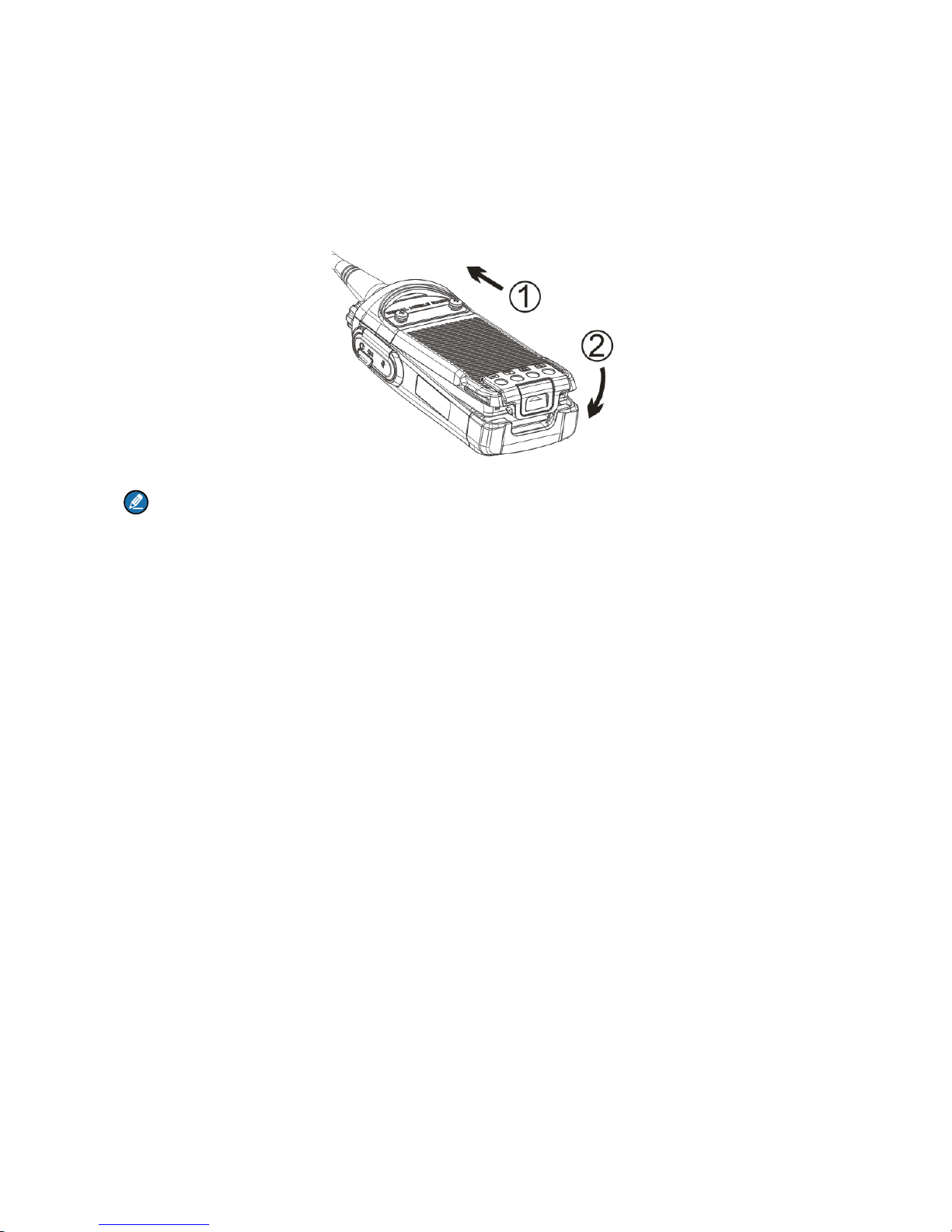
3.2 Attaching the Antenna......................................................................................................................4
3.3 Attaching the Belt Clip......................................................................................................................4
3.4 Attaching the Accessories................................................................................................................4
3.5 Charging the Battery.........................................................................................................................6
4. Status Indications ................................................................................................................................8
4.1 LCD Icon...........................................................................................................................................8
4.2 LED Indicator....................................................................................................................................9
5. Menu Navigation.................................................................................................................................10
6. Basic Operations................................................................................................................................ 11
6.1 Turning the Radio On/Off...............................................................................................................11
6.2 Adjusting the Volume......................................................................................................................11
6.3 Selecting a Zone.............................................................................................................................11
6.4 Selecting a Channel .......................................................................................................................11
6.5 Locking and Unlocking the Keypad................................................................................................11
7. Call Services.......................................................................................................................................13
7.1 Call on Digital Channel .............................................................................................................13
7.2 Call on Analog Channel ...........................................................................................................14
8. Features and Operations................................................................................................................... 15
8.1 Home Screen..................................................................................................................................15
8.2 Managing the Contact ..............................................................................................................15
8.3 Message ...................................................................................................................................15
8.4 Call Log ....................................................................................................................................16
8.5 Scan................................................................................................................................................17
8.6 Setting the Radio............................................................................................................................18
8.7 Device Information..........................................................................................................................20
8.8 One Touch Call ........................................................................................................................20
8.9 Time-out Timer (TOT).....................................................................................................................21
8.10 Busy Channel Lockout..................................................................................................................21
8.11 Monitor ....................................................................................................................................21

8.12 CTCSS/ CDCSS .....................................................................................................................21
8.13 Squelch Off ..............................................................................................................................22
8.14 TDMA Direct Mode .................................................................................................................22
8.15 VOX ..............................................................................................................................................22
8.16 CDC/CTC Selected ................................................................................................................23
9. Troubleshooting.................................................................................................................................24
10. Care and Cleaning............................................................................................................................26
11. Optional Accessories ......................................................................................................................27
12. Technical Parameters......................................................................................................................28
13. FCC Statement..................................................................................................................................29
14. IC Statement .....................................................................................................................................30

1. Items in the Package
Please unpack carefully and check if all items listed below are received. If any item is missing or
damaged, please contact your dealer.
Radio Battery Charger
Power Adapter Antenna Belt Clip
Strap Documentation Kit
Note
The frequency band is marked on the label of antenna as follows
Frequency band: VHF 136MHz to 150MHz
Frequency band: VHF 146MHz to 174MHz
1

2. Product Overview
2.1 Product Controls
No. Part Name No. Part Name
○
1EPTT (Push-to-Talk) Key A○
8ELED Indicator
A○
2ESK1 (Side Key 1) A○
9EPower On/Off/Volume Control Knob
A○
3ESK2 (Side Key 2) A○
10EAccessory Connector
A○
4ECall Key(programmable)A○
11EBattery Latch Call End Key
A○
5EChannel Selector Knob A○
12EAntenna
A○
6ELCD Display Speaker A○
13EBelt Clip
A○
7EMicrophone A○
14EBattery
2.2 Programmable Keys
For enhanced convenience, you may request your dealer to program the SK1, SK2, P1, P2 and P3 keys
as shortcuts to certain feature. 2

3. Before Use
3.1 Attaching the Battery
To attach the battery, do as follows.
Note
To remove the battery, please turn off the radio first. Then slide the battery latch upwards to unlock
the battery.
3

3.2 Attaching the Antenna
Caution
Do not hold the radio by its antenna, otherwise the performance and lifespan of the antenna will be
reduced.
3.3 Attaching the Belt Clip
To attach the belt clip, do as follows.
Step 1 Remove the screws.
Step 2 Align the screw holes on the belt clip with those on the radio’s back, and then tighten the
screws.
3.4 Attaching the Accessories
Step 1 Open the accessory connector cover as shown below.
4

Step 2 Align the accessory (such as an audio accessory, or a programming cable) plug with the
accessory connector.
Step 3 Tighten the screw on the plug.
5

3.5 Charging the Battery
7TCaution
10TMake sure the radio is powered off before charging. Read the Safety Information Booklet in
advance to get necessary safety information.
10TCharge a new battery for at least 5 hours before initial use for best performance.
Please use the charger specified by the Company to charge the battery. Charging Diagram is listed
below.
Charging the radio (with battery attached) Charging the battery
Charging Status Indication (on charger):
6

LED Indication Charging Status
The LED Indicator
flashes red slowly.
Standby (no load)
The LED Indicator
glows red.
Charging
The LED Indicator
glows orange.
90% charged
The LED Indicator
glows green.
Fully charged
The LED Indicator
flashes red rapidly.
Charging failure
7

4. Status Indications
4.1 LCD Icon
Name Icon Radio Status
Battery Power Icon More bars indicate more battery power.
TX Power Icon Low TX power for the current channel.
High TX power for the current channel.
Accessory Icon An accessory is connected.
Operation Mode Icon
Direct Mode: Under this mode, the radio can
communicate with each other directly.
Repea
ter Mode: Under this mode, the radio can
communicate with each other via a repeater.
TDMA Direct Mode: Under this mode, two
individual calls can be supported simultaneously
on the 12.5 kHz channel.
Monitor Icon The Monitor feature is active.
Scan Icon
The radio is scanning.
The radio stays on a non-priority channel.
The radio stays on priority channel 1.
The radio stays on priority channel 2.
Missed Call Icon Missed call(s).
Message Icon New message/unread message.
Inbox is full.
RSSI Icon No signal.
More bars indicate stronger signal strength.
Speaker Icon The speaker is unmuted.
Call/Contact Icon Indicates a private call in progress.
Indicates a private contact in the contact list.
8

Name Icon Radio Status
Indicates a group call in progress.
Indicates a group contact in the contact list.
Indicates an all call in progress.
Indicates an all call contact in the contact list.
4.2 LED Indicator
LED Indication Radio Status
The LED
indicator flashes
green.
Powering on
The LED
indicator glows
green.
Receiving
The LED
indicator glows
red.
Transmitting
The LED
indicator flashes
orange slowly.
Scanning
The LED
indicator glows
orange.
Call hang time.
No voice is being transmitted or received on the traffic channel
during a call. Within such period, you can hold down the PTT key to talk to the
other party.
9

5. Menu Navigation
The following diagram outlines the menu structure of the radio. You can personalize menu option
displayed in the radio via your dealer.
To select and confirm the options shown in the menu, press the OK/Menu key and then press the Up or
Down key to select your needed option, finally press the OK/Menu key. This manual only describes the
paths to the menus in terms of menu operations, for example, to access the contact list, go to “Menu ->
Contact -> Contact List”.
The radio supports menu reset function. If you do not operate the menu for a predefined time period set
by the dealer, the radio will automatically return to the home screen. You may request your dealer to
configure the auto reset time or disable the feature.
Menu
Contact Message Call Logs Settings
Zone
Contact
List
Favorite
Contact Quick Text
Outbox
Inbox
Outgoing
Incoming
Missed
Keypad
Lock
Power Level
Radio Set
Backlight
Device Info
Tones
LEDCovert Mode
Scan List
Scan
Scan
On/Off
Talk
Around
Adjust Squelch Level
VOX
10

6. Basic Operations
6.1 Turning the Radio On/Off
To turn on the radio, rotate the Power On/Off/Volume Control knob clockwise until you hear a click. To
turn off the radio, rotate the knob counter-clockwise until you hear a click.
If the Channel Notify upon Power-on feature is enabled by your dealer, the radio will announce the
channel number upon power-on.
6.2 Adjusting the Volume
After the radio is powered on, you can rotate the Power On/Off/Volume Control knob clockwise to
increase the voice volume, and rotate the knob counter-clockwise to decease it.
6.3 Selecting a Zone
A zone is a group of channels with the same property, which can facilitate convenient management over
the channels. The radio supports 2 zones, each of which consists of up to 16 channels. You can select a
zone through any of the following ways:
Menu Operation: Go to “Menu -> Zone”, press the Up or Down key to select an appropriate zone,
and then press the OK/Menu key to confirm it.
Shortcut key: You can toggle to the appropriate zone by pressing the programmed Zone Up or Zone
Down key preset by your dealer.
If the Zone Notify feature is enabled by your dealer, the radio will announce the zone number when
selecting zone.
6.4 Selecting a Channel
After the radio is powered on, you can rotate the Channel Selector Knob to select an appropriate
channel.
If the Channel Notify feature is enabled by your dealer, the radio will announce the channel number upon
channel switching.
6.5 Locking and Unlocking the Keypad
When the keypad is not in use, you can lock the keypad to prevent accidental keypad operation. The
following methods are available for you to lock or unlock the keypad:
11

Key Combination: press the OK/Menu key and then press P1 to lock the keypad; press Any Key and
P1 to unlock it.
Note
Any Key cannot be PTT, SK1 and SK2 key.
Shortcut key: Press the programmed Keypad Lock key to lock or unlock the keypad.
Menu: Go to “Menu -> Settings -> Radio Set -> Keypad Lock” and then select “Enable” or “Disable”.
Enable: The keypad will be locked automatically if no operation is made within the preset time
period. However, you can unlock the keypad via the key combination or the programmed Keypad
Lock key mentioned above.
Disable: The keypad will not be locked automatically. However, you can lock or unlock the keypad
via the key combination or Keypad Lock key mentioned above.
12

7. Call Services
After the radio is powered on, you can make and receive calls. To ensure optimal volume of the
receiving radio, keep the microphone about 2.5 to 5 centimeters away from your mouth when the radio is
transmitting.
Private call: It is a voice call between one individual user and another individual user.
Group call: It is a voice call between one individual user and a predefined group of users.All parties
in the group can communicate with each other.
All call: It is a one-way voice call from any user to all users on a channel.
7.1 Call on Digital Channel
You can initiate a private call, group call or all call (programmed by your dealer) through the same
operations on digital channel. When calling back, the radio will make a call to the calling party in private
call; but in group call, the radio will make a call to all parties involved when calling back. And you cannot
call back in an all call.
Here takes the private call between Radio A and Radio B for example:
Preset contact
Step 1 Radio A and B select the same digital channel.
You may preset a regular private call/group call/all call contact for each digital channel via your
dealer.
Step 2 Radio A holds down the PTT key to initiate a call.
Step 3 By holding down the PTT key, Radio A can talk to the microphone when the LED indicator
glows red and the radio displays the icon .
Step 4 Radio B can receive the call without any operation.When the radio is receiving, the LED
indicator glows green and the radio displays the icon .
Step 5 Radio B can hold down the PTT key to talk when the LED indicator glows orange and the radio
displays the icon . 13

If you do not respond to it, the radio will provide appropriate indications.
Step 6 Radio A can receive the call without any operation.When the radio is receiving, the LED
indicator glows green and the radio displays the icon .
Step 7 Radio A can hold down the PTT key to talk when the LED indicator glows orange and the radio
displays the icon .
Contact List or Call Log
Step 1 Radio A and B select the same digital channel.
Step 2 Radio A accesses the contact list via menu “Menu -> Contact -> Contact List”, “Menu ->
Contact -> Favorite Contact” or “Menu -> Call Log -> Outgoing/Incoming/Missed”.
Step 3 Radio A presses the Up or Down key to select Radio B.
Step 4 Radio A holds down the PTT key to initiate a call.
Step 5 By holding down the PTT key, Radio A can talk to the microphone when the LED indicator
glows red and the radio displays the icon .
Step 6 Radio B can receive the call without any operation.When the radio is receiving, the LED
indicator glows green and the radio displays the icon .
Step 7 Radio B can hold down the PTT key to talk when the LED indicator glows orange and the radio
displays the icon .
If you do not respond to it, the radio will provide appropriate indications.
Step 8 Radio A can receive the call without any operation.When the radio is receiving, the LED
indicator glows green and the radio displays the icon .
Step 9 Radio A can hold down the PTT key to talk when the LED indicator glows orange and the radio
displays the icon .
0TNote
The Call Hang Time (the duration of LED indicator glowing orange) is preset by your dealer. If neither
party talks before this duration expires, the call will end.
7.2 Call on Analog Channel
The calling operations on the analog channel are the same as that on the digital channel. The difference
is that the called parties are all the users on the channel, rather than the preset contact for the channel.
14

8. Features and Operations
8.1 Home Screen
Description
This feature allows the radio to return to the home screen directly.
Operation
To return to the home screen directly, press .
8.2 Managing the Contact
Contact allows you to manage your contacts via the menu, for example, viewing contact’s information,
adding new contacts, setting the frequently-used contacts and deleting contacts.
8.2.1 Contact List
Description
The Contact List is used to save Private Call/Group Call/All Call contacts information which is preset by
the dealer.
Operation
Go to “Menu -> Contact -> Contact List” to access the contact list.
Press the programmed Contact List key to access the contact list.
Press to access the contact list.
Under this sub-menu, you can view the contact details.
8.2.2 Favorite Contact
Description
Favorite Contact allows you to add the frequently used contacts from Contact List.
Operation
Go to “Menu -> Contact -> Favorite Contact” to access the favorite contact list.
In the “Favorite Contact” menu, you can check the contact information or delete the contacts.
8.3 Message
You can send the Quick Text message directly. In the inbox, you can reply, forward or delete the text
message, and in the outbox you can also resend, forward or delete the message.
Go to “Menu -> Message” to configure the corresponding features.
15
Other manuals for PD48X
1
Table of contents
Other Hytera Portable Radio manuals

Hytera
Hytera PD78X Series User manual

Hytera
Hytera PD36X User manual

Hytera
Hytera BP36X User manual

Hytera
Hytera X1ei User manual

Hytera
Hytera PD715 Rx User manual

Hytera
Hytera PD46X User manual

Hytera
Hytera HP7 Series User manual

Hytera
Hytera AR482Gi User manual

Hytera
Hytera PD362 User manual

Hytera
Hytera PD71XIS User manual

Hytera
Hytera PD602 User manual

Hytera
Hytera PD785 User manual

Hytera
Hytera PD79XIS FM IIB User manual

Hytera
Hytera TC610 User manual

Hytera
Hytera PD78X Series User manual

Hytera
Hytera PD60Xi Um User manual

Hytera
Hytera HP78X User manual

Hytera
Hytera BD612i User manual

Hytera
Hytera PD782iG User manual

Hytera
Hytera MD78XG User manual