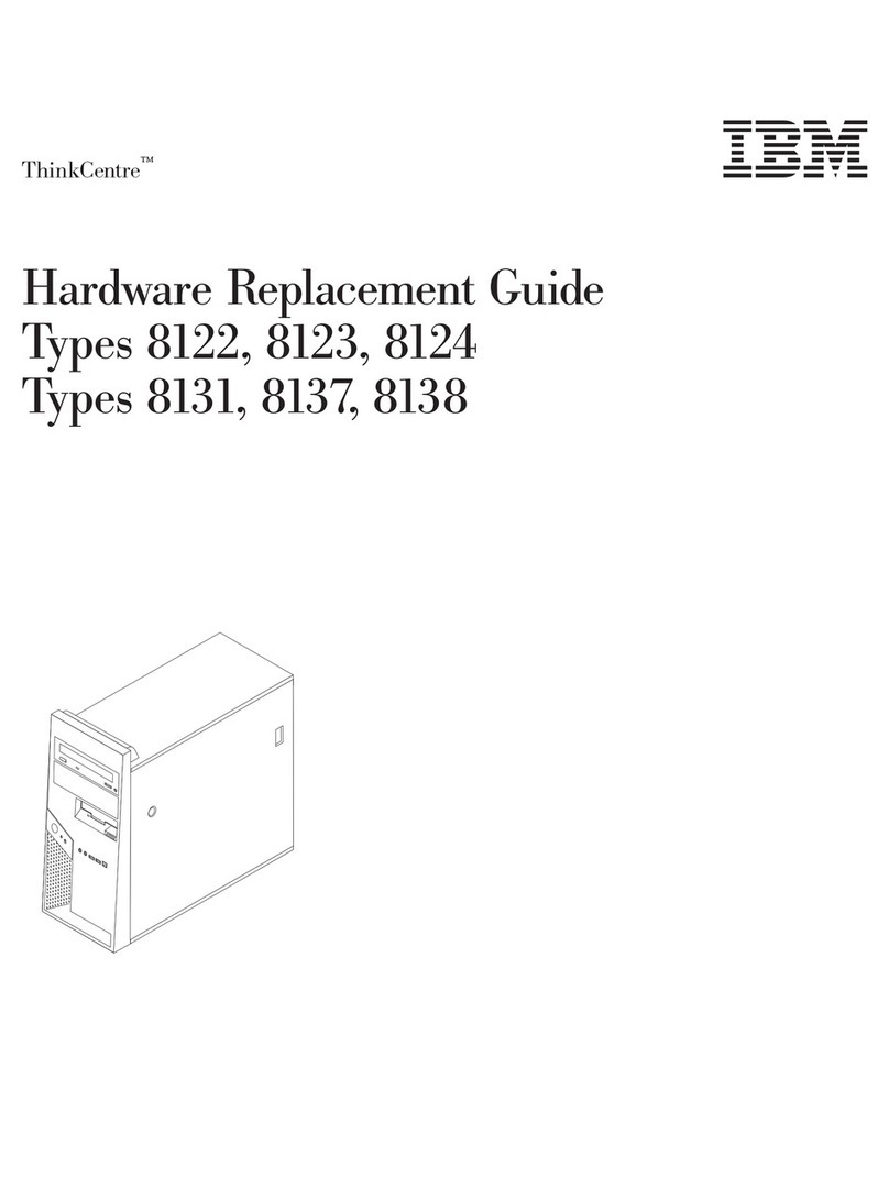
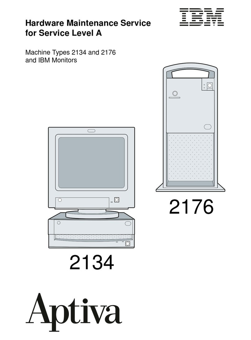
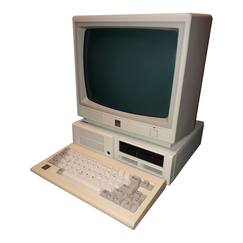
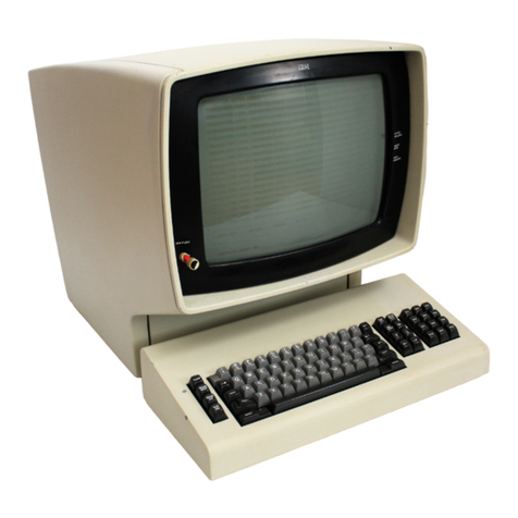
IBM 5150 Quick user guide

April 2011
IMPORTANT
1. The motherboard described in this document is the
first motherboard, the 16KB-64KB one.
2. If the BIOS on the 16KB-64KB motherboard has
been upgraded to the third revision one, then the
switch settings shown for SW2 (“switch 2”) on the
motherboard no longer apply.
The BIOS revision can be determined by examination
of the seven digit number on motherboard chip U33.
First revision: 5700051
Second revision: 5700671
Third revision: 1501476


---
-
----
-
---
-----
- --
---
--
---
Personal Computer
-----
Hardware Reference
--_.-
Library
Technical
Reference

FEDERAL
COMMUNICATIONS
COMMISSION
RADIO
FREQUENCY
INTERFERENCE
STATEMENT
WARNING: This
equipment
has been certified
to
comply with
the
limits for a Class B computing device, pursuant to Subpart J
of
Part
.~
15
of
FCC rules. Only peripherals
(computer
input/output
devices,
terminals, printers, etc.) certified
to
comply with
the
Class B limits
may be
attached
to
this computer. Operation with non-certified
peripherals
is
likely
to
result in interference
to
radio and
TV
reception.
First Edition (August 1981)
Changes are periodically made to the information herein; these changes will be
incorporated
in
new editions
of
this publication.
Products
are
not stocked at the address below. Requests for copies
of
this
product and for technical information about the system should
be
made to
your authorized
IBM
Personal Computer Dealer.
A Product Comment Form
is
provided
at
the back
of
this publication.
If
this
form has been removed, address comment to:
IBM
Corp., Personal Computer,
P.O. Box 1328, Boca Raton, Florida 33432.
IBM
may use or distribute any
of
the information you supply
in
any way it believes appropriate without incurring
any obligations whatever.
© Copyright International Business Machines Corporation 1981

PREFACE
~
The IBMPersonal ComputerTechnicalReference Manual
is
designed
to provide hardware design and interface information. Thispublication
also provides Basic InputOutputSystem(BIOS) information as well as
programming support matter.
This manual is intended for programmers, engineers involved in
hardware and software design, designers, and interested persons who
have a needto know how the IBM Personal Computeris designed and
works.
This manual has three sections:
Section - 1
"HARDWARE
OVERVIEW,"
features anoverview
ofthe
system as
a whole calling outspecific items such as the System Unit, Keyboard,
IBM Monochrome Display and the 80
CPS
Matrix Printer.
Section - 2
"
HARDWARE,"
contains adescriptionfor eachfunctional partofthe
system. This sectionalso contains specifications for power, timing, and
interface. Programmingconsiderations are supportedbycodingtables,
command codes and registers.
Section - 3
"ROM
and SYSTEM
USAGE,"
describes BIOSas well as how touse
BIOS, interrupt vector listings, memory map, vectors with special
meanings, a cassette section, a keyboard encoding section, and a
set
of
Low Memory Maps.
"APPENDICES,"
to address the
ROM
BIOS listing, an instruction
set, logic diagrams, and expanded charts used to support specific
hardware descriptions.


CONTENTS
SECTION
1.
HARDWARE
OVERVIEW
.........
1-1
System Block Diagram
............................
1-4
SECTION
2.
HARDWARE
......................
2-1
System Board
...................................
2-3
System Board
Data
Flow
..........................
2-6
I/O
Channel
.....................................
2-8
I/O
Channel Diagram
............................
2-9
System Board
I/O
Channel Description
.............
2-10
System Board Component Diagram
.................
2-13
Keyboard
........................................
2-14
Keyboard Interface Block Diagram
.................
2-15
Keyboard Diagram
...............................
2-16
Keyboard Scan Codes
.............................
2-17
Keyboard Interface Connector Specifications
.........
2-18
Cassette User Interface
............................
2-19
Cassette Jumpers
...............................
2-19
Circuit Block Diagrams
.........................
2-19
Cassette Interface Connector Specifications
..........
2-21
Speaker Interface
.................................
2-22
Speaker Drive System Block Diagram
.............
2-22
I/O
Address Map
.................................
2-23
System Memory Map
.............................
2-25
SystemBoardAndMemoryExpansionSwitchSettings
...
2-28
5
1/4"
Diskette Drives Switch Settings
..............
2-29
Monitor Type Switch Settings
....
,
.....
,
...........
2-29
System Board Memory Switch Settings
..............
2-30
32/64
KB
MemoryExpansionOptionSwitchSettings
...
2-31
Power Supply
...................................
2-33
Power Supply Location
............................
2-34
Input Requirements
...............................
2-34
DC
Output
......................................
2-34
AC
Output
......................................
2-34
Power Supply Connectors And Pin Assignments
......
2-35
Important Operating Characteristics
.................
2-36
Over Voltage/Current Protection
.................
2-36
Signal Requirements
............................
2-36
iii

IBM
Monochrome
Display
and
Parallel
Printer
Adapter
.................................
2-37
Parallel Interface Description
IBM Monochrome Direct Drive Interface and
......................
2-37
IBM Monochrome Display Adapter Block Diagram
...
2-38
System Channel Interface
..........................
2-39
Lines Used
....................................
2-39
Loads
.........................................
2-39
Special Timing
.................................
2-39
Data
Rates
....................................
2-39
Interrupt and
DMA
Response Requirements
.......
2-39
Modes
Of
Operation
..............................
2-40
Programming Considerations
.......................
2-41
Programming the 6845
CRT
Controller
...........
2-41
Sequence
of
Events
.............................
2-41
Memory Requirements
..........................
2-41
DMA
Channel
.................................
2-42
Interrupt Levels
................................
2-42
I/O
Address and Bit Map
.......................
2-42
IBM Monochrome Display
........................
2-43
Operating Characteristics
........................
2-43
Pin Assignment
.................................
2-44
Color/Graphics
Monitor
Adapter
.................
2-45
Color/Graphics Monitor Adapter Block Diagram
.....
2-47
Major Components Definitions
.....................
2-48
Motorola 6845 CRT Controller
..................
2-48
Mode Set and Status Registers
...................
2-48
Display Buffer
.................................
2-48
Character Generator
............................
2-48
Timing Generator
..............................
2-48
Composite Color Generator.
.....................
2-48
Modes of Operation
...............................
2-49
Alphanumeric Mode
............................
2-49
Color TV
......................................
2-49
Color Monitor
.................................
2-50
IBMMonochromeDisplayAdapterV
s.
Color/Graphics
..
.
Adapter Attribute Relationship
.....................
2-51
Color/Graphics Modes
............................
2-51
Graphics Storage Map
..........................
2-52
Description of Basic Operations
..................
2-54
Summary
of
Available Colors
....................
2-55
iv

Programming Considerations
.......................
2-55
Color/Graphics Monitor Adapter Direct Drive, and
Color/Graphics Monitor Adapter Auxiliary
Programming The 6845 Controller
................
2-55
6845 Register Description
.......................
2-56
ProgrammingtheMode Control and StatusRegister
...
2-57
Color Select Register
...........................
2-57
Mode Select Register
...........................
2-58
Mode Register Summary
........................
2-58
Status Register
.................................
2-59
Sequence of Events
.............................
2-59
Memory Requirements
..........................
2-60
Interrupt Level
.................................
2-60
I/O
Address and Bit Map
.......................
2-61
Composite Interface Pin Assignment
...............
2-62
Video Connectors
...............................
2-63
Parallel Printer
Adapter
..........................
2-65
Parallel Printer Adapter Interface Connector
Connector Pin Assignment and Descriptions
of
Parallel Printer Block Diagram
.....................
2-66
Programming Considerations
.......................
2-67
Specifications
...................................
2-69
IBM 80 CPS Matrix Printer
.......................
2-70
Printer Specifications
..............................
2-71
Setting The
DIP
Switches
.........................
2-72
Functions and Conditions
of
DIP
Switch 1
........
2-72
Functions and Conditions
of
DIP
Switch 2
........
2-73
Parallel Interface Description
......................
2-73
Interface Signals
..............................
2-74
Parallel Interface Timing Diagram
................
2-77
ASCII
Coding Table
..............................
2-78
ASCII
Control Codes
.............................
2-79
5
1/4"
Diskette Drive
Adapter
....................
2-89
5
1/4"
Diskette Drive Adapter Block Diagram
.......
2-90
Functional Description
............................
2-91
Digital Output Register
..........................
2-91
Floppy Disk Controller.
.........................
2-91
Programming Considerations
.......................
2-94
Symbol Descriptions
............................
2-94
Command Summary
............................
2-96
Command Status Registers
......................
2-100
v
Progranuning Summary
............................
2-103
5
1/4"
Diskette Drive Adapter Internal Interface
5
1/4"
Diskette Drive Adapter External Interface
DPC
Registers
.................................
2-103
Drive Constants
................................
2-104
Comments
.....................................
2-104
System
I/O
Channel Interface
......................
2-104
Drive A and B Interface
...........................
2-106
Adapter Outputs
...............................
2-106
Adapter Inputs
.................................
2-107
Specifications
...................................
2-108
Specifications
...................................
2-109
5
1/4"
Diskette Drive
.............................
2-110
Diskettes
........................................
2-111
Mechanical and Electrical Specifications
............
2-112
Memory
Expansion
Options
......................
2-113
Operating Characteristics
..........................
2-113
Memory Module Description
.......................
2-114
Memory Module Pin Configuration
.................
2-114
Switch Configurable Start Address
..................
2-115
Game
Control
Adapter
...........................
2-117
Game Control Adapter Block Diagram
..............
2-117
Functional Description
............................
2-118
Address Decode
................................
2-118
Data
Buss Buffer/Driver
........................
2-118
Trigger Buttons
.................................
2-118
Joystick
Po~tions
..............................
2-118
I/O
Channel Description
..........................
2-119
Interface Description
..............................
2-119
Joystick Schematic
................................
2-121
Game Control Adapter (Analog Input) Connector
Specifications
...................................
2-122
Asynchronous
Communications
Adapter
..........
2-123
Asynchronous Communications Adapter Block
Diagram
.......................................
2-124
Modes of Operation
...............................
2-125
I/O
Decode for Communications Adapter
.........
2-125
Interrupts
......................................
2-126
Interface Description
..............................
2-126
Current Loop Interface
..........................
2-127
Voltage Interchange Information
..................
2-128
vi

INS 8250 Functional Pin Description
...............
2-129
Input Signals
...................................
2-129
Output Signals
.................................
2-132
Input/Output Signals
............................
2-133
Programming Considerations
.......................
2-133
Asynchronous Communications Reset Functions
...
2-133
INS 8250 Accessable Registers
..................
2-134
INS 8250 Line Control Register.
.................
2-134
INS 8250 Programmable Baud Rate Generator
....
2-135
Line Status Register
............................
2-137
Interrupt Identification Register
..................
2-139
Interrupt Enable Register
........................
2-141
Modem Control Register
........................
2-142
Modem Status Register.
.........................
2-143
Receiver Buffer Register
.........................
2-144
Transmitter Holding Register
....................
2-145
Selecting The Interface Format.
....................
2-146
Asynchronous Communications Adapter Connector
Interface Specifications
..........................
2-147
SECTION
3.
ROM
and
SYSTEM
USAGE
.......
3-1
ROM
BIOS
.....................................
3-2
Use of BIOS
.....................................
3-2
Parameter Passing
................................
3-2
Interrupt Vector Listing
............................
3-3
Vectors With Special Meaning
.....................
3-5
Interrupt 1
CH
-Timer Tick
......................
3-5
Interrupt
IDH
-Video Parameters
................
3-5
Interrupt
lEH
-Diskette Parameters
..............
3-5
Interrupt
IFH
-Graphics Character Extensions
....
3-6
Other Read/Write Memory Usage
................
3-6
BIOS Programming Tip
...........................
3-6
BIOS Memory Map
...............................
3-7
BIOS Cassette Logic
.............................
3-8
Interrupt
15
......................................
3-8
Cassette Write
...................................
3-8
Cassette Read
....................................
3-9
Data Record Architecture
..........................
3-10
Error Recovery
...................................
3-10
vii

Keyboard
Encoding
and
Usage
...................
3-11
Encoding
........................................
3-11
Character Codes
..................................
3-11
Extended Codes
..................................
3-13
Extended Functions
............................
3-13
Shift States
....................................
3-14
Shift Key Priorities
.............................
3-15
Special Handling
.................................
3-15
System Reset
..................................
3-15
Break
.........................................
3-16
Pause
.........................................
3-16
Print Screen
...................................
3-16
Keyboard Usage
..................................
3-17
BASIC Screen Editor Special Functions
.............
3-19
DOS
Special Functions
...........................
3-19
Low
Memory
Maps
..............................
3-21
0-7F
Interrupt Vectors
............................
3-21
BASIC and
DOS
Reserved Interrupts
(80-3FF)
......
3-22
Reserved Memory Locations
(400-5FF)
.............
3-22
BASIC Workspace Variables
......................
3-23
APPENDICES
..................................
A-O
Appendix
A:
ROM
BIOS
Listing
.................
A-I
Appendix
B:
Assembly
Instruction
Set
Reference
...
B-1
AppendixC:
Of
Characters
Keystrokes
and
Color
....
C-l
Appendix
D:
Logic
Diagrams
.....................
D-l
Appendix
E:
Unit
Specifications
..................
E-l
Glossary
.........................................
G-l
Bibliography
....................................
Bib-l
Index
...........................................
1-1
viii

FIGURE LISTING
1.
System Block Diagram
........................
1-4
2.
System Board
Data
Flow
......................
2-6, 7
3.
I/O
Channel Diagram
.........................
2-9
4.
System Board Component Diagram
.............
2-13
5.
Keyboard Interface Block Diagram
..............
2-15
6.
Keyboard Diagram
............................
2-16
7.
Cassette Interface Read Hardware
..............
2-19
8.
Cassette Interface Write Hardware
..............
2-20
9.
Cassette Motor Control.
.......................
2-20
10. Speaker Drive System Block Diagram
...........
2-22
11. System Memory Map
.........................
2-25
12. System Memory Map (Increments of I6KB)
.....
2-26
13.
Power Supply and Connectors
..................
2-35
14.
IBMMonochrome DisplayAdapterBlockDiagram
...
2-38
15.
Color/GraphicsMonitorAdapterBlockDiagram
...
2-47
16.
Parallel Printer Adapter Block Diagram
.........
2-66
17. Location of(Printer)
DIP
Switches
.............
2-72
18. Parallel Interface Timing
.......................
2-77
19. 5
1/4"
Diskette Drive Adapter Block Diagram
...
2-90
20. Game Control Adapter Block Diagram
..........
2-117
21. Joystick Schematic
............................
2-121
22. Asynchronous Communications Adapter
Block Diagram
...............................
2-124
23. Current Loop Interface
........................
2-127
24. Selecting The Interface Format
.................
2-146
25. BIOS Memory Map
...........................
3-7
ix

TABLE LISTING
1.
lCeyboard Scan Codes
.........................
2-17
2.
6845 Initialization Parameters
..................
2-41
3.
Monochrome
Vs
Color/Graphics Attributes
......
2-51
4. Color/Graphics Modes
........................
2-51
5.
Summary of Available Colors
..................
2-55
6.
6845 Register Description
.....................
2-56
7.
Printer Specifications
..........................
2-71
8.
Functions and Conditions of
DIP
Switch 1
.......
2-72
9.
Functions and Conditions of
DIP
Switch 2
.......
2-73
10. Connector Pin Assignment and
Description ofInterface Signals
.................
2-74
11. ASCII Coding Table
..........................
2-78
12.
DCl/DC3
and Data Entry
.....................
2-82
13. Symbol Description
...........................
2-94
14. Status Register O
..............................
2-100
15. Status Register
1.
.............................
2-101
16. Status Register 2
..............................
2-102
17. Status Register 3
..............................
2-103
18. Mechanical and Electrical Specifications
.........
2-112
19.
Memory Module Pin Configuration
.............
2-114
20.
DIP
Module Start Address
.....................
2-115
21.
I/O
Decodes (3F8 -
3FF)
.....................
2-125
22. Asynchronous Communications ResetFunctions
...
2-133
23. BAUD Rate at 1.843 Mhz
.....................
2-137
24. Interrupt Control Functions (Asynchronous)
.....
2-140
25. Character Codes
..............................
3-11
26. lCeyboard Extended Functions
..................
3-14
27. lCeyboard -Commonly Used Functions
..........
3-17
28. Basic Screen Editor Special Functions
...........
3-19
29. DOS Special Functions
........................
3-19
30. 0-7F Interrupt Vectors
........................
3-21
31. Basic & DOS Reserved Interrupts (80-3FF)
.....
3-22
32. Reserved Memory Locations (400-5FF)
.........
3-22
x

SECTION I.
HARDWARE OVERVIEW
The IBM Personal Computer has two major elements; a System Unit
"..-..."
and a keyboard. In addition, a variety
of
options are offered including
one or two 5-1/4" Diskette Drives with adapter which can be housed
inside the System Unit, an IBM Monochrome Display, an 80 CPS
Matrix Printer, two display adapters, storage increments to 256 KB, an
Asynchronous Communications Adapter, Printer Adapter and a
Game Control Adapter.
The System Unit
is
the heart
of
your IBM Personal Computer system.
The System Unit houses the microprocessor, Read-Only Memory
(ROM), Read/Write Memory, Power Supply, and System Expansion
Slots for the attachment
of
up to
five
options. One
or
two
5-1/4"
Diskette Drives can also be mounted in the system Unit providing
160KB
of
storage each.
The System Board is a large board which fits horizontally in the base
of
the System Unit and includes the microprocessor, 40KB
ROM
and
16KB memory. The memory can be expanded in 16KB increments to
64KB. The System Board also includes an enhanced version
of
the
Microsoft BASIC-80 Interpreter without diskette functions. The
BASIC Interpreter
is
included in the ROM. The System Board also
permits the attachment
of
an audio cassette recorder for loading or
saving programs and data.
The System Unitpower system
is
a 63.5 watt, 4 level
DC
and 120 AC
unit. It
is
a switching regulator design" allowing for light weight and
high efficiency. The
DC
power capacity
is
designed to support an
expanded system.
The 5-1/4" Diskette Drive Adapter
fits
into one ofthe five System
Expansion Slots. This attachment supports two internal drives. The
5-1/4" Diskette Drive Adapter uses write precompensation and a
phase lock loop for clock and data recovery.
The 5-1/4" Diskette Drive permits the IBM Personal Computer to
read, write and store data on 5-1/4" diskettes. Each diskette stores
approximately 160KB
of
data. Two
of
these drives may be installed
internally in the System Unit.
The keyboard
is
attachedto the System Unitwith a light-weight, coiled
cable. The keyboard features 83 keys, and offers commonly used data
and word processing functions in a design combining the familiar
typewriter and calculator pad layouts.
1-1

A base system requires one
of
two different display adapters, either a
Color/Graphics medium resolution Monitor adapter or a high
resolution monochrome alphanumeric adapter with a parallel printer
adapter.
The Color/Graphics adapter operates at standard television fre-
quencies (15,750Hz), allowing attachment to a variety of industry
~
standard monitors, including home TVs with a user supplied
RF
modulator.
The Color/Graphic Monitor adapter supports a variety of modes
selected by program control. The adapter supports color or black and
white alphanumeric modes with line width
of
40 or 80 characters and
25
lines. In the alphanumeric mode there are 256 characters.
This adapter provides both a standard composite video and direct
drive outputs. In addition, a light pen feature input port
is
provided.
The IBM Monochrome Display
is
a high resolution green phosphor
display offering the personal computer user quality usually found on
larger computer systems. The display features an 11-1/2"screen with
an anti-glare surface and a variety ofhighlighting choices. The screen
displays
25
lines
of
80 characters.
It
supports 256 different letters,
numbers and special characters that are formed
in
a nine by 14 dot
matrU.
~
The IBMMonochrome Displayrequires the Monochrome Display and
PrinterAdapterOption. This option installs
in
one
of
the System Unit's
five
System Expansion Slots. The display
is
powered from the System
Unit.
The 80 CPS Matrix Printer
is
a versatile, low cost, quality printer
for
the IBM Personal Computer.
It
prints in both directions at a nominal
horizontal speed
of
80 characterspersecondon continuous-feed, single
ormulti-partpaper. Theprinterfeatures four charactersizes(
40,66,80
or 132 characters per line), Power-on Self-test and simple paper
loading and ribbon cartridge uppercase and lower case ASCII char-
acter set and 64 special graphic characters.
The 80 CPS Matrix Printer requires either the Monochrome Display
and PrinterAdapteror the PrinterAdapter. These options install in one
of the Systems Unit's five System Expansion Slots. The Printer
requires standard 120 volt, 60 Hz power through its own power cord.
~
The printer requires the Printer Cable Option for attachment to the
System Unit.
1-2

The 16KBMemory Expansion Kits allow you to increase the memory
size
of
yourIBM p.ersonal Computer. The base systemcomes standard
with 16KB
of
memory.
Up
to three 16KB Memory Expansion Kits
maybe installedto increase the memory size to 64KB. Memory can
be
furtherincreasedto 256KB with additional memory options once these
three Expansion Kits are installed.
~e
Expansion Kits plug into the System Board and must be installed
sequentially. They do not occupy any
of
the
five
System Expansion
Slots.
The 32KB and 64KB Memory Expansion Options permit you to
increase memory capacity beyond 64KB. Multiple 32KB and 64KB
Memory Expansion Options may be installed as long as System
Expansion Slots are available. A maximum
of
three 64KB memory
options may be installed for a total of 256KB
of
memory.
The 32KB and 64KB Memory Expansion Options require a System
Expansion Slot
in
the System Unit. The first 64KB on the System
Board
is
requiredbefore 32KB and64KB Memory ExpansionOptions
can be installed.
The Asynchronous Communications Adapter provides a channel to
data processing or input/output devices outside of your immediate
~
system. These can be connected by telephone using a plug-in modem,
qr
directly by cable when the device is nearby.
This option utilizes the RS232C asynchronous (start-stop) interface
permitting attachment to a variety
of
devices including a large "host"
computer
or
another IBM p.ersonal Computer.
This option supports 50 to 9600 BPS transmission speeds. One
25
pin
"D"
shell, male type connector
is
providedto attach various peripheral
devices. A "current loop" interface
is
located in the same connector,
and ajumperblock
is
provided to manually selecteither the voltage or
the current loop interface.
The Asynchronous Communications Adapter requires a System
Expansion Slot
in
the System Unit. Anexternal modem
is
required for
telephone line transmission.
The Game Control Adapter permits the attachment of user-supplied
joysticks
or
paddles. Two joysticks and up to four paddles may be
~.
attached. IBMdoes notmanufacture eitherthejoysticks orthe paddles.
This option provides connectors for joysticks orpaddles and requires a
System Expansion Slot in the System Unit.
A block diagram
of
the system
is
on the following page (1-4).
1-3

System Block Diagram
8088
20
81T
•
OSC
MAIN 4
CH
•
elK
PROCESSING
DMA
•
CNTRL
UNIT
ROS
ROS
8K
x8
8K
x 8
ROS
ROS
8K
x 8
BK
x 8
ROS
ROS
8Kx 8
BK
x8
KEYBOARO
ATTACHMENT
110
CHANNEL
3
CH
8
LEV.
16
BIT
INTR
TIC
16
x9
READ!
WRITE
MEMORY
16KB
MEMORY
EXPANSION
16KB
MEMORY
EXPANSION
16KB
MEMORY
EXPANSION
SYSTEM
80ARD
Figure
1.
SYSTEM
BLOCK
DIAGRAM
1-4

SECTION 2. HARDWARE
~
Contents:
System Board . . . . . . . . . . . . . . . . . . . . . . . . . . . . . . . . . . .
2-3
Power
Supply.
. . . . . . . . . . . . . . . . . . . . . . . . . . . . . . . . . . 2-33
IBM
Monochrome Display And Printer
Adapter...
2-37
IBM Monochrome
Display.
. . . . . . . . . . . . . . . . . . . . . . 2-43
Color/Graphics Monitor
Adapter.
. . . .
..
. . . . . . . . . . 2-45
Printer Adapter and Printer. . . . . . . . . . . . . . . . . . . . . . . 2-65
5-1/4" Diskette Drive
Adapter.
. . . . . . . . . . . . . . . . . . . 2-89
5-1/4" Diskette
Drive............................
2-110
Memory Expansion Options 32KB and 64KB. . . . . . 2-113
Game Control Adapter. . . . . . . . . . . . . . . . . . . . . . . . . . . 2-117
Asynchronous Communications Adapter . . . . . . . . . . 2-123
2-1
Other manuals for 5150
3
Table of contents
Other IBM Desktop manuals

IBM
IBM NetVista A21 User manual

IBM
IBM 2283 Owner's manual

IBM
IBM PC 300 User manual

IBM
IBM NetVista Setup guide

IBM
IBM NetVista A20 User manual

IBM
IBM NetVista Owner's manual

IBM
IBM NetVista A22p User manual

IBM
IBM NetVista A20 Troubleshooting guide

IBM
IBM NetVista Troubleshooting guide

IBM
IBM PC 300 User manual

IBM
IBM NetVista S42 User manual

IBM
IBM 9114-275 - IntelliStation POWER 275 User manual

IBM
IBM PC 300 User manual

IBM
IBM NetVista User manual

IBM
IBM IntelliStation M Pro 6225 User manual

IBM
IBM PS/2 L40 SX Service manual

IBM
IBM 8874 - eServer xSeries MXE 460 User manual

IBM
IBM 3196 Manual

IBM
IBM IntelliStation 6866 Owner's manual

IBM
IBM NetVista X40 User manual