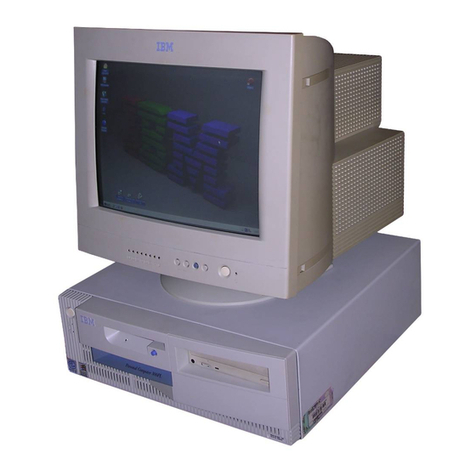
IBM RS/6000 44P 170 User manual

RS/6000 44P Series Model 170
Installation Guide
SA38-0561-02
IBM

Third Edition (October 2000)
Before using this information and the product it supports, read the information in “Safety Notices” on page vii,
“Appendix B. Environmental Notices” on page 57, and “Appendix C. Notices” on page 59.
©International Business Machines Corporation 1999, 2000. All rights reserved.
Note to U.S. Government Users - Documentation related to restricted rights - Use, duplication, or disclosure is subject
to the restrictions set forth in the GSA ADP Schedule Contract with IBM Corp.

Contents
Safety Notices........................vii
Electrical Safety .......................vii
Unit Emissions ........................viii
Laser Safety Information ....................viii
Data Integrity and Verification ..................ix
About This Book .......................xi
ISO 9000 ..........................xi
Online Publications.......................xi
Related Publications ......................xi
Trademarks .........................xi
Chapter 1. Setting Up the RS/6000 44P Series Model 170 .........1
Unpacking Your System Unit ...................1
Step 1: Check Your Inventory ...................1
Step 2: Read the Safety Notices ..................2
Step 3: Need Help? ......................2
Step 4: Are All of the Internal Options Installed? .............2
Step 5: Position the System Unit and Display ..............3
Step 6: Check Your Display Type ..................3
Step 7: Connect the Display ....................4
Step 8: Attach the Display Cable Toroid ................4
Step 9: Connect the Adapter Cables .................5
Step 10: Connect the First External SCSI Device .............6
Step 11: Connect Additional External SCSI Devices ............7
Step 12: Connect the Serial and Parallel Devices.............8
Step 13: Connect the Keyboard, Mouse, and Tablet ............9
Step 14: Connect the Audio Cables .................10
Step 15: Are You Using an Ethernet Connection? ............11
Step 16: Connect Twisted-Pair Ethernet ...............12
Step 17: Connect Thick Ethernet ..................13
Step 18: Plug in the Power Cables .................15
Step 19: Your System Unit Is Now Set Up...............16
Step 20: Go to Your Operating System Documentation ..........16
Chapter 2. Verifying the Hardware Operation .............17
Step 1. Considerations before Running This Procedure ..........17
Step 2. Loading the Diagnostics ..................17
Step 3. Running System Verification.................18
Step 4. Additional System Verification ................18
Step 5. Stopping the Diagnostics ..................18
Chapter 3. Installing Options for the RS/6000 44P Series Model 170.....21
Safety Considerations .....................21
Handling Static-Sensitive Devices .................21
Stopping the System Unit ....................22
iii

Covers ..........................23
Removing the Left Side Cover..................23
Replacing the Left Side Cover..................25
Cover Support Bridge .....................26
Removing the Cover Support Bridge................26
Replacing the Cover Support Bridge................26
Battery ..........................27
Removing the Battery ....................27
Replacing the Battery ....................28
Option List .........................30
Memory Modules .......................30
Removing Memory Modules ..................30
Installing Memory Modules ...................32
Processor Card .......................34
Removing the Processor Card..................34
Installing the Processor Card ..................35
Adapters ..........................36
Removing Adapters .....................36
Installing Adapters......................38
Internal Drives ........................40
Checklist for Handling Drives ..................40
Configuring a Drive ......................41
Drive Configuring ......................41
Drive Unconfiguring .....................41
Disk Drives .........................42
Removing Disk Drives ....................42
Installing Disk Drives .....................43
Media Drives ........................45
Removing CD-ROM Drives and Tape Drives .............45
Installing Media Drives ....................45
Optional Media Usage .....................46
Preparing Optional Media ...................46
Installing Optional Media ...................48
Installing an Optional Disk Drive .................48
Installing an Optional Media Fan Assembly .............49
System Firmware Updates ....................51
Checking the Current Firmware Levels ...............51
Appendix A. Communications Statements ..............53
Federal Communications Commission (FCC) Statement ..........53
European Union (EU) Statement ..................54
International Electrotechnical Commission (IEC) Statement .........54
United Kingdom Telecommunications Safety Requirements .........54
Avis de conformité aux normes du ministère des Communications du Canada. . . 55
Canadian Department of Communications Compliance Statement .......55
VCCI Statement .......................55
Radio Protection for Germany ...................55
Appendix B. Environmental Notices ................57
Product Recycling and Disposal ..................57
iv 44P Series Model 170 Installation Guide
Environmental Design .....................57
Appendix C. Notices .....................59
Appendix D. System Records ..................61
Identification Numbers .....................61
Device Records .......................62
SCSI IDs and Bay Locations ..................63
Appendix E. General Attributes Required When Using a TTY Terminal ....65
Appendix F. ........................67
Additional Communication Attributes.................67
Additional Keyboard Attributes...................68
Additional Printer Attributes....................68
Index ...........................69
Reader’s Comments — We’d Like to Hear From You ..........71
Contents v

vi 44P Series Model 170 Installation Guide

Safety Notices
A
danger
notice indicates the presence of a hazard that has the potential of causing
death or serious personal injury.
Danger notices appear on the following pages:
vvii
v21
A
caution
notice indicates the presence of a hazard that has the potential of causing
moderate or minor personal injury.
Caution notices appear on the following pages:
vviii
v21
v27
Note: For a translation of these notices, see
System Unit Safety Information
, order
number SA23-2652
Electrical Safety
Observe the following safety instructions any time you are connecting or disconnecting
devices attached to the workstation.
DANGER
An electrical outlet that is not correctly wired could place hazardous voltage
on metal parts of the system or the devices that attach to the system. It is the
responsibility of the customer to ensure that the outlet is correctly wired and
grounded to prevent an electrical shock.
Before installing or removing signal cables, ensure that the power cables for
the system unit and all attached devices are unplugged.
When adding or removing any additional devices to or from the system,
ensure that the power cables for those devices are unplugged before the
signal cables are connected. If possible, disconnect all power cables from the
existing system before you add a device.
Use one hand, when possible, to connect or disconnect signal cables to
prevent a possible shock from touching two surfaces with different electrical
potentials.
During an electrical storm, do not connect cables for display stations, printers,
telephones, or station protectors for communication lines.
vii

CAUTION:
This product is equipped with a three–wire power cable and plug for the user’s
safety. Use this power cable with a properly grounded electrical outlet to avoid
electrical shock.
DANGER
To prevent electrical shock hazard, disconnect the power cable
Unit Emissions
The unit-related emission value is equal to or lower than 70dB(A).
Der Geräuschpegel der Einheit ist kleiner oder gleich 70 db(A).
Laser Safety Information
The optical drive in this system unit is a laser product. The optical drive has a label that
identifies its classification. The label, located on the drive, is shown below.
The optical drive in this system unit is certified in the U.S. to conform to the
requirements of the Department of Health and Human Services 21 Code of Federal
Regulations (DHHS 21 CFR) Subchapter J for Class 1 laser products. Elsewhere, the
drive is certified to conform to the requirements of the International Electrotechnical
Commission (IEC) 825 (1st edition 1984) and CENELEC EN 60 825:1991 for Class 1
laser products.
CAUTION:
A class 3 laser is contained in the device. Do not attempt to operate the drive
while it is disassembled. Do not attempt to open the covers of the drive as it is
not serviceable and is to be replaced as a unit.
Class 1 laser products are not considered to be hazardous. The optical drive contains
internally a Class 3B gallium-arsenide laser that is nominally 30 milliwatts at 830
nanometers. The design incorporates a combination of enclosures, electronics, and
redundant interlocks such that there is no exposure to laser radiation above a Class 1
level during normal operation, user maintenance, or servicing conditions.
CLASS1 LASERPRODUCT
LASERKLASSE 1
LUOKAN1 LASERLAITE
APPAREIL A LASER DECLASSE 1
IEC825:1984 CENELEC EN60 825:1991
viii 44P Series Model 170 Installation Guide
Data Integrity and Verification
IBM computer systems contain mechanisms designed to reduce the possibility of
undetected data corruption or loss. This risk, however, cannot be eliminated. Users who
experience unplanned outages, system failures, power fluctuations or outages, or
component failures must verify the accuracy of operations performed and data saved or
transmitted by the system at or near the time of the outage or failure. In addition, users
must establish procedures to ensure that there is independent data verification before
relying on such data in sensitive or critical operations. Users should periodically check
the IBM support websites for updated information and fixes applicable to the system and
related software.
ix

x44P Series Model 170 Installation Guide
About This Book
This book provides information on how to set up your system, install and remove
options, use diagnostics and service aids, as well as verify system operation. This book
also provides information to help you solve some of the simpler problems that might
occur.
ISO 9000
ISO 9000 registered quality systems were used in the development and manufacturing
of this product.
Online Publications
RS/6000 publications are available online. To access the online books, visit our Web
site at: http://www.rs6000.ibm.com/resource/hardware_docs/
Related Publications
The following publications provide additional information about your system unit:
vThe
RS/6000 44P Series Model 170 User’s Guide
, order number SA38-0559,
contains information to help users set up their system unit, install, configure, and
modify options, and solve minor problems.
vThe
RS/6000 44P Series Model 170 Service Guide
, order number SA38-0560,
contains reference information, maintenance analysis procedures (MAPs), error
codes, removal and replacement procedured, and a parts catalog.
v
Diagnostic Information for Multiple Bus Systems
, order number SA38-0509, contains
diagnostic information, service request numbers (SRNs), and failing function codes
(FFCs).
vThe
IBM RS/6000 Adapters, Devices, and Cable Information for Multiple Bus
Systems
, order number SA38-0516, contains information about adapters, devices,
and cables for your system. This manual is intended to supplement the service
information found in the
Diagnostic Information for Multiple Bus Systems
.
vThe
Site and Hardware Planning Guide
, order number SA38-0508, contains
information to help you plan your installation.
vThe
PCI Adapter Placement Reference
, order number SA38-0538, contains
information about PCI adapter placement in your system unit.
Trademarks
The following terms are trademarks of International Business Machines Corporation in
the United States, other countries, or both:
vAIX
vRS/6000
xi

Other company, product, and service names may be trademarks or service marks of
others.
xii 44P Series Model 170 Installation Guide

Chapter 1. Setting Up the RS/6000 44P Series Model 170
Follow the procedures in this chapter to install the RS/6000 44P Series Model 170.
Unpacking Your System Unit
CAUTION:
This unit weighs between from 18 kg (39.7 pounds) and 32 kg (70.5 pounds). Two
persons are required to safely move it. Using less than two persons to move it
can result in injury.
1. Remove the top cover of the system unit carton.
2. Lift the system unit out of the carton base.
Step 1: Check Your Inventory
hBooks, CD-ROM &
other media h″About Your
Machine″document hSystem unit hDisplay and system
unit power cables (2)
h9-pin to 25-pin serial
converters (2)(optional) hSCSI converter cable
(optional) hASCII terminal
(optional) hKeyboard (optional)
Wrist/palm rest
(optional)
hDisplay and cable
toroid (optional) hMouse (optional)
1

Step 2: Read the Safety Notices
Safety Note: Before continuing, refer to the System Unit Safety Information book for
Danger and Caution notices. Do not plug any cables into the system unit,
adapters, or electrical outlets until you have reviewed this information.
Make sure none of the power cords are connected before continuing to
the next step.
Step 3: Need Help?
If you encounter difficulties while setting up your system unit, contact your sales
representative for assistance.
Step 4: Are All of the Internal Options Installed?
These instructions are for RS/6000 44P Series Model 170 systems that have internal
options (such as adapters, disk drives, or memory upgrades) already installed. If you
have internal options that are not installed, go to “Chapter 3. Installing Options for the
RS/6000 44P Series Model 170” on page 21, then return to “Step 5: Position the
System Unit and Display” on page 3.
244P Series Model 170 Installation Guide
Step 5: Position the System Unit and Display
Position the system unit and display (optional) at or near their finished location.
Observe the following guidelines when positioning the system unit and display:
vLeave enough space around the system unit to safely and easily complete the setup
procedures.
vObserve standard ergonomic guidelines while arranging your system unit so that you
can work comfortably and safely. For more information on arranging your workstation,
visit the Healthy Computing Web site at: http://www.pc.ibm.com/us/healthycomputing
vThe system unit weighs between 17.7 kg (39 pounds) and 20.4 kg (45 pounds). Two
people are recommended to safely move it. Using less than two persons to move it
can result in injury or damage to the machine.
vBe sure to maintain at least 76 mm (3 inches) of space in front and behind the
system unit to allow the system unit to cool properly. Blocking the air vents can
cause overheating, which might result in a malfunction or permanent damage to the
system unit.
vPlace the system unit in a location where it can safely and easily reach any
necessary power outlets and network connections.
vDisplays or ASCII terminals can weigh as much as 35 kg (77 pounds). Use caution
when lifting or moving the display or ASCII terminal.
vPlace the display or ASCII terminal in a stable and sturdy location.
Step 6: Check Your Display Type
If you ordered a display with your system unit, the system unit has been set to use the
highest display resolution and refresh rate available for that display. If you want to:
vAttach a different display to your system unit
vChange the default display resolution or refresh rate
then after completing the installation steps, refer to the Customer Installable Options
Library CD-ROM for the documentation on the graphics adapter to learn how to change
the settings for the display you are installing.
Chapter 1. Setting Up the RS/6000 44P Series Model 170 3

Step 7: Connect the Display
Connect the graphics display cable to the back of the display and to the graphics
adapter connector.
For more display instructions, see your display documentation.
Note: Some displays require an additional cable.
If you have an ASCII terminal, you must connect it to the serial connector S1, but do
not connect it at this time. Wait until you reach “Step 12: Connect the Serial and
Parallel Devices” on page 8 for instructions.
Step 8: Attach the Display Cable Toroid
If the cable for your display does not include a toroid, locate the toroid shipped with
your system unit and follow the installation instructions included with the toroid.
.
444P Series Model 170 Installation Guide
Step 9: Connect the Adapter Cables
If you are using any optional adapters (such as Token-Ring or 8-port EIA-232), connect
the cables to the appropriate connectors in slots 1 through 6.
Chapter 1. Setting Up the RS/6000 44P Series Model 170 5

Step 10: Connect the First External SCSI Device
If you need to connect an external SCSI device, follow these steps. If you ordered the
optional SCSI converter cable and need it to connect an external SCSI device, begin
with step 1. If you do not need the converter cable, begin with step 3. If you have no
external SCSI devices to attach, skip to “Step 12: Connect the Serial and Parallel
Devices” on page 8.
1. Connect the Ultra 2 SCSI end of the converter cable directly to the system unit.
2. Connect the other end of the SCSI converter cable to one end of the SCSI device
cable.
3. Connect the other end of the SCSI device cable to the SCSI device.
4. Connect the SCSI device terminator (if this is the last device to be connected). The
last device on a SCSI bus
must
be terminated.
Note: When a cable is not attached to the SCSI connector on the system unit, the
connector is automatically terminated (internally).
5. Refer to the SCSI device documentation to set the SCSI device address. For future
reference, you can record the address in “Appendix D. System Records” on
page 61.
2
3
4
1
2
644P Series Model 170 Installation Guide
Step 11: Connect Additional External SCSI Devices
1. Locate the last SCSI device in the chain from the system unit. Remove the SCSI
device terminator (if it is installed).
2. Connect the new SCSI cable where you just removed the SCSI device terminator.
3. Connect the other end of the SCSI cable to the new SCSI device.
4. Connect the SCSI device terminator.
5. Repeat the above steps for each additional SCSI device you attach.
6. Refer to the SCSI device documentation to set the SCSI device address. For future
reference, you can record the address in “Appendix D. System Records” on
page 61.
Chapter 1. Setting Up the RS/6000 44P Series Model 170 7

Step 12: Connect the Serial and Parallel Devices
If you have a parallel device (such as a printer), connect it to the parallel connector.
If you have one serial device, connect it to the serial connector S1. If you have an
ASCII terminal, you must connect it to the serial connector S1. An additional serial
device can be connected to the S2 connector.
Two 9-to-25-pin serial converters are optional with your system unit to increase serial
device compatibility.
1
3
2
1S1 Serial Connector
2S2 Serial Connector
3Parallel Connector
844P Series Model 170 Installation Guide

Table of contents
Other IBM Desktop manuals

IBM
IBM 3290 User manual

IBM
IBM MICRO TOWER 2169 Owner's manual

IBM
IBM NetVista A21 User manual

IBM
IBM PC 300PL Types 6862 User manual

IBM
IBM HC10 - BladeCenter - 7996 User manual

IBM
IBM SYSTEM/36 5362 User instructions

IBM
IBM ThinkCentre 8171 Parts list manual

IBM
IBM NetVista X40 Mounting instructions

IBM
IBM NetVista A22p User manual

IBM
IBM 3179 User manual

IBM
IBM 3278 Setup guide

IBM
IBM NetVista User manual

IBM
IBM HC10 - BladeCenter - 7996 User manual

IBM
IBM NetVista A22p User manual

IBM
IBM Aptiva Series User manual

IBM
IBM PC 300GL Types 6275 User manual

IBM
IBM NetVista 6049 User manual

IBM
IBM NetVista X40 User manual

IBM
IBM P 75 486 User manual

IBM
IBM NetVista X40 Manual