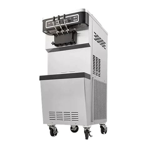
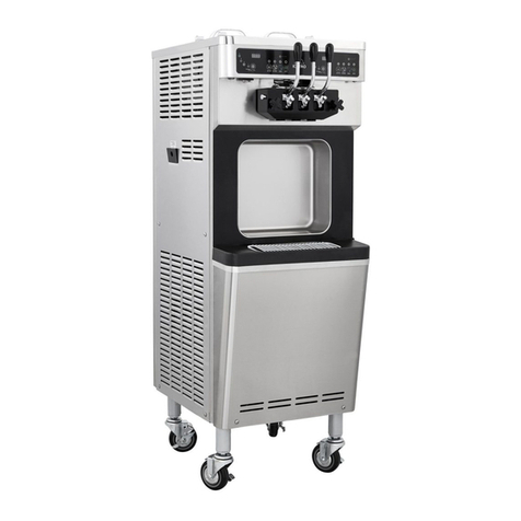
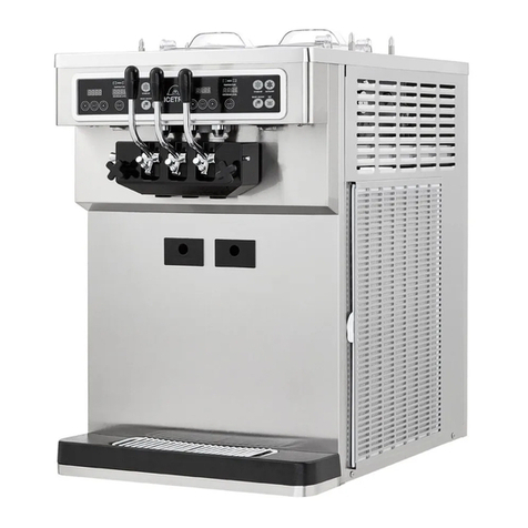
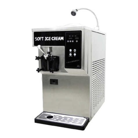
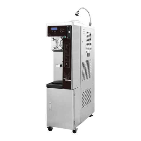
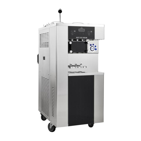
icetro SSI-141TG User manual

* It cannot be used in a foreign country
where the supply voltage is different.
* This product is designed for indoor use
* Make sure to install it indoors.
* The appearance, design, color, and parts
of the product are subject to Change
without prior notic
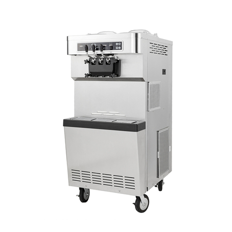
SSI-141TG
SMALL-SIZED ICE CREAM FREEZER
User’s Manual

2
Contents
Chapter 1. Safety Instructions ……………………………………………………………… 3
Chapter 2. Installation and external view …………………………………………………… 8
Chapter 3. Functional Description …………………………………………………………… 9
Chapter 4. Assembly and Wash……………………………………………………………… 12
Chapter 5. Checklists for Major Machine Component Management …………………… 17
Chapter 6. Troubleshooting Guidelines …………………………………………………… 18
Chapter 7. Parts Replacement Periods …………………………………………………… 20
Chapter 8. Product Specications …………………………………………………………… 21
Chapter 9. How to inject Refrigerant………………………………………………………… 22
Chapter 10. Circuit Diagram ………………………………………………………………… 23
Chapter 11. Part List ………………………………………………………………………… 24
Product Warranty ……………………………………………………………………………… 28

3
In order to prevent accidents caused by wrong use and to conveniently use the
product, be cautious of the following: Be sure to understand the following symbols
and their descriptions rst.
If you neglect this symbol and wrongly use the product, it may cause a
re, serious injury or death.
Danger
Warning
If you neglect this symbol and wrongly use the product, it may cause a
re or injury.
Caution
If you neglect this symbol and wrongly use the product, it may cause a
personal injury or a property loss.
※Personal Injury: Minor cuts, burns (high or low temperature) or electric shocks
that do not need hospitalization or long-term hospital visiting.
※Property Loss: The loss on houses, household goods, livestock, bedding, and
such.
Each symbol has the following meanings:
General danger, warning, and caution
No contact!
General thing forbidden
Keep from re!
Thing to be followed
Must be grounded
Do not disassemble!
Risk of electric shock!
Risk of burn!
Chapter 1. Safety Instructions

4
For relocation of the product, call an
expert(*)
The product may cause such hazards as
falling down unless properly installed. It should
be installed in accordance with related
regulations such as KS standards, the road
and trafc act. The re ghting act and the food
sanitation act.
※Call your distributor.
Ground the product properly.
If the product is not properly
grounded, it may cause
electric leakage or shock.
Do not connect the ground
wire to a running water
pipe or gas pipe, as
this may cause an
electric shock or explosion.
Make sure to connect the product to the
power mains through a dedicated circuit
breaker.
Do not operate the product while all panels
are not well fastened enough.
Call an expert(*) for repair.
Imperfect repair may cause re, electric
shock or injury.
※If you think the product
needs repairing, call
your distributor.
When you dispose of the product,
consult a disposal expert(*)
An accident may
result unless it is
properly disposed
of.
※Call your
distributor.
Keep your warning and caution labels
clean for easy legibility.
If the user misunderstands
the content of such a label,
an accident may occur.
Do not disassemble or alter the product.
Electric shock, re or
injury may result.
Keep a heating device away from the
power cord.
A heating device may melt
down the coating of the
power core, resulting
in re or electric shock.
Do not put anything on the power cord.
Make sure that the power cord is not
twisted or knotted.
Fire or electric shock
may result.
Prohibited Prohibited
Warnings
Call a service center
Observe the regulations Ground the product
Check your labels Prohibited
Label
Warning
Caution
Oh! NO

5
If the earth leakage breaker is in the ‘off’
position, do not turn it to the ‘on’ position
by force.
If you turn it ‘on’ while the
machine is defective, re
or electric shock may result.
Unplug the power cord and
call a service center.
Stop using the machine, if you nd the
power cord, power receptacle or any
other cord to be defective.
Fire or electric shock may result.
Do not inject inammable material such
as benzene, gasoline, paint thinner or LP
gas into the product otto keep it close to
product.
Explosion, re or
injury may result.
Use the cream mix designated by your
distributor only.
An unauthorized mix that is excessively
diluted with water may cause the product to
break down.
Do not spray with an insecticide,
ammable spray or perfume near the
product.
It may cause a product
failure or re.
Do not touch any moving part inside the
product.
You may get injured.
When you remove a plug or connector,
do so holding the plug or connector.
If you pull out a plug or
connector with excessive
force, electric Shock or
defect may result.
Stop operating the product if you hear
any unusual noise or smell or if you see
smoke coming out from the product.
If you continue to
operate the machine
in such a condition,
re or electric
shock may result.
Do not touch the power plug or any
elctric part with a wet
hand.
Electric shock may result.
Do not climb onto the product or shake
or tilt it.
The product may fall down
or develop a problem.
Do not touch
Prohibited Prohibited
Prohibited
Prohibited
Caution
Warnings
Prohibited
Thinner
LP
Gas
B
E
N
Z
E
N
E
Ga
sol
ine
Prohibited
Unplug the power cord
Prohibited
Plug or connector

6
Do not put anything on the product.
Injury may result if it falls over.
Pay attention to the metallic edges and
vent louvers.
Do not touch the metallic edges or vent
louvers.
Do not place any obstacle at the
entrance of the air vent.
The side and rear of the product should be
maintained at least 20cm from the wall.
If so, the performance will be degraded.
Cannot be educated the person or the
child whom cannot touches or does not
operate do not to make can.
The damage will go to the machine or there is
a possibility which Will be injured.
When you replenish ice cream mix, do
not allow rain or snow to get into any
interior electric part.
Defective operation may
result.
Do not touch a high-temperature
interior part.
There is a caution label on high-temperature
parts. If you touch such a part, burn or unex-
pected injury may result.
Make sure that no electric part has come
into contact with water.
If the product was
immersed in water by
a ood, call a service
center for a check.
Otherwise, re or electric
shock due to electric
leakage may result.
If the machine is not in use for an
extended period of time , store
machine after cleaning it and turning off
the erath leakageBreaker at the rear, or
consult your distributor.
Ice cream mix may decay or coli bacteria
may propagate.
Caution
Caution Do not touch
Warnings
Caution Caution
Caution Caution
Prohibited

7
Before you clean the inside of the prod-
uct, unplug the power cord and wear
rubber gloves.
Electric shock or injury may result.
Make sure to wear gloves when you clean
the condenser.
· You may get your hand injured by a sharp
edge on the condenser.
· Use a n cleaning
agent and brush.
※A metallic brush
with hard,
pointed bristles
must not be
used.
Empty the drain water trap regularly.
Stagnant water may decay or, if the water
overows, it may cause re or electric shock.
If you sell or hand over the product, make
sure to hand over the user’s Manual with
it.
Without the manual,
an accident may occur
because of erroneous
handling or operation.
Do not insert your nger or other
materials into the panel rubber or the
machine supply.
Strongly warn children about its danger.
It may cause an electric shock or product
damage.
If the power cord needs replacement or
repair, request a service center or expert.
Wear gloves
Caution
Caution
CautionCaution
Caution
Service center
User’s
Manual
Caution

8
The freezer system needs a clearance of 20 cm from any side equipment.
If the clearance is not secured, the freezer will lose freezing capability and the
compressor may become permanently damaged.
Mix cover
Cover
handle
Control
buttons
Power switch
AL LEVEL
Discharge
outlet
Drain
water trap
Earth
leakage
breaker
Filter
guide
Rubber
foot
Exterior View
Power supply suitable for the capacity of the product is required.
Therefore it is necessary to check the condition of the power mains at the location of
installation and install a separate power supply system if the capacity is insufcient.
(Refer to Chapter 8 ‘Product Specications.’)
In addition, make sure to use a dedicated power receptacle. If the receptacle is shared
with another electric machine or device, malfunction, electric leakage or a re caused by
overheating may occur.
Drain hole
Chapter 2. Installation and external view
Freezer system
Electrical conncetion
Dasher cover
Right side
panel

9
YOGURT & SOFT ICE CREAM FREEZER
STANDBY
Power switch SALE SIGNAL
LEVER
HIGH REFRIGERATION
STANDARD
REFRIGERTION
YOGURT ICE CREAM
(LAMP FLASH)
SOFT ICE CREAM
(LAMP ON)
STANDARD
SOFT REFRIGERATION
FREEZING
CONTROL LEVEL
REFRIGERATION
CONTROL LEVEL
MODE BUTTON
Press button while
3 seconds.
When it will be highly
refrigertion, it is one
of the causes of solution
supplying problem.
FREEZING LEVEL
5
4
3
2
1
WASH AUTO
Chapter 3. Functional Description
· When this switch is turned on, you can start manipulating the control panel on the front.
Power switch
Standby
It is possible to store the mix in the mix container at a cold temperature to suppress
propagation of bacteria at or below 4.4.
When it is necessary to store the mix for extended period of time without selling the
ice cream, the machine keeps the mix at a constant temperature between 1.7 and 4.4,
thereby preventing overcooling. When you push the button, the lamp will be turned on and
the mode starts. In the standby mode, the wash and the auto function are turned off. To
restore normal operation, push the “AUTO” button. When the machine stops rotating, the
ice cream in the freezer cylinder will become very sticky.
Mix level indicator lamp -“MIX LOW”
· “The mix level indicator lamp is located above the button. If the lamp blinks, it
means that the level of mix is low and that the mix should be replenished as soon as
possible. The level of the mix container should always be maintained at a position where
the mix can sufciently touch the level sensing rod. If the mix is not replenished in timely
manner. It may freeze up.
· A frozen mix Container may cause damage to the dasher, the blade, the driver shaft and
the discharge outlet.
Caution
Each indicating lamp or push button makes a sound. Whenever it is
pushed down. To cancel a function push the function button once again.
The lamp will turned off and the function canceled.

10
AT INITIAL SET UP
At “mix low” (no raw material), press the control level button for 5 seconds.
Then, the LED lamp will blink sequentially and remember the free load status of the
motor.
· This applies to the rst time installation, motor replacement, and variation of supply
voltage.
FREEZING CONTROL LEVEL
This function controls the density of ice-cream.
Higher LED button gures produce harder ice-cream, and lower gures produce softer
ice-cream.
REFRIGERATION CONTROL LEVEL
This function controls freezing storage temperature.
“HIGH” LED button indicates lower storage temperature.
“SOFT” LED button indicates higher storage temperature.
WASH
Pressing the “WASH” button will light up the lamp.
This indicates operation of the dasher motor. Use this function to wash the product.
See Page12~15 for cleaning method.
AUTO
When the “AUTO” button is pressed, the lamp will light up and ice-cream begins to be
produced. At this time, the raw material in the storage container is cooled down.
This function must be used only when producing ice-cream.

11
CABURATOR CONTROL
The carburetor is consisted of two parts.
The part that is inserted into the hole of the mixing tank is called
the body and a tube is inserted into this.The tube has a hole at
thetop and at the bottom. It can’t be inserted in the reverse direc-
tion.
The gure shows the caburator with a blocked hole.
If you align the no hole of the upper area of the caburator body
with the area having no hole in the upper area of the tube, then
the hole in the lower area of the caburator body will be blocked.
Condition of use: Initial soft ice cream making.
This gure shows the caburator aligned with a large hole.
Align the large hole of the upper area of the caburator body
with the large hole in the upper area of the tube. Decrease the
overrun and increase the amount of ingredients injection in this
way when you need continuous vending of the product.
Condition of use: When the “AUTO” mode is executed
This gure shows the caburator aligned with a small hole.
Align the small hole of the upper area of the caburator body
with the small hole in the upper area of the tube. Then, it will be
aligned with the small hole in the lower area of the caburator
body. Increase the overrun and decrease the amount of ingre-
dients injection in this way when you expect a small amount of
sales. Condition of use: When the “AUTO” mode is executed
This gure shows the caburator aligned with a medium hole.
Align the medium hole of the upper area of the caburator body
with the medium hole in the upper area of the tube. Then, it will
be aligned with the medium hole in the lower area of the cabura-
tor body. It will make the overrun and the amount of ingredients
iinjection at medium level for sales. Condition of use: When the
“AUTO” mode is executed
A small hole can improve the overrun, but it may depend on the amount of ingre-
dients in the mixing tank. The fewer ingredient is in the mixing tank, the higher the
overrun becomes.The more the ingredient is, the lower the overrun becomes.
For your
information

12
Do not disassemble the product, such as the dasher cover, stirrer blade, or drive shaft,
when not all the control switches are turned OFF. Failure to observe this warning can
result in personal injury by moving parts.
In principle, start the machine when it is fully dried, and when operation is over, keep it
dry after disassembling and washing it.
This chapter explains how to assemble parts that have been washed. Make sure to
use fresh mix.
Assembly Step
(SFBTF
Spiral
dasher lug pom
packing javara
dasher assy
①Apply grease to the groove at
the end of the shaft. Never apply
grease to the hexagonal end of
the drive shaft.
② Insert the exible packing until
it ts with the last groove apply
grease inside the exible
packing.
③Assembly the dasher cover as
shown in the gure.
④Take care to insert the packing
javara in the correct direction.
Chapter 4. Assembly and Wash

13
$BSCVSFUPS
⑤Insert the supply pipe into the
mix container with the hole facing
downward.
⑥Push in the dasher blade on the shaft
inside the cylinder. Join it accurately so
that the dasher will not protrude outside.
Attempt to rotate the dasher blade with
a hand. You can conrm that it is
properly tted into the groove if the
dasher blade does not rotate.
⑦Apply edible grease to the
packing that goes inside the shaft.
If the packing is damaged or worn out,
replace it with a new one.
⑧Apply edible grease into the hole
of the dasher cover, and insert
the shaft from an upside down
position.
⑨Insert the handle into the shaft
and join it by pushing the
sideways
⑩Insert the gasket and the
white-colored bearing into the dasher
cover with the wider side of the
bearing facing the dasher cover as
shown in the picture. Do not apply
edible grease.

14
4&/403
⑪Put the dasher cover into the
machine and tighten two hand
screws. Tighten two hand screws.
Tighten the screws sufciently but
not excessively.
⑫Install the drain water trap and its
cover.
⑬Install the drain hole on the
front.
⑭Fill the mix container with mix
ot such a level that the mix
sufciently covers the sensor.

15
Step 1: Prepare 7.6 liters of detergent uid(e.g. vegetable detergent for kitchen use)
diluted with water.
Use warm water and follow the specications of the manufacturer.
Step 2: Pour 7.6 liters of detergent and water into the hopper and let it ow into the freezer
cylinder.
Step 3: While the detergent uid ows into the freezer cylinder, wash the mix container with
a brush. Brush carefully when you wash the mix container hole, the
carburetor, the mix container gasket and the level sending rod on the wall behind
the mix container.
Step 4: Set the power switch to the “ON” position.
Step 5: Push the “WASH” switch At this time, the detergend uid will be agitated in the
freezer cylinder.
Let it continue for about 5 minutes.
Step 6: Drain the detergent uid by turning
the handle over.
(Place a bucket to collect drain
water as shown in the picture)
Overhaul steps
Step 1: Make sure that the power switch is in the “OFF” position. Double-check that the
indication and operation lamps on the control panel are turned off.
Step 2: Remove the bolts, the dasher assembly, the dasher, the dasher blade and the drive
shaft from the freezer cylinder. Immerse these components in detergent uid for a
thorough wash.
Step 3: Remove the front-side water trap and the drain hole.
Wash Step

16
Brush Cleaning Step
Step 1: Use warm water or detergent uid.
Step 2: Remove the exible hose from the drive shaft.
Step 3: Remover the following parts from the assembly.
* Gasket
* Handle
* Design cap
* Piston
Remove O-rings.
Step 4: Inject a very small amount of detergent uid into the freezer cylinder.
Clean the rear bearing of the freezer cylinder by scrubbing it with a brush.
Step 5: Remove the drain water trap and clean it.
Condenser Cleaning Step
Step 1: Turn the power switch
off and remove the
right-side panel.
Step 2: Pull out the ler and
wash it with neutral
detergent or remove
dust.
Step 3: Dry up the lter and
reassemble it in the
reverse order.
Step 6: Clean all the parts and components that have been disassembled thoroughly
with detergent uid and make sure that grease and mix have completely
removed. Pay special attention when cleaning the dasher assembly. Lay all
cleaned parts and components on a clean place and wipe them with dry cloth
or dry them up sufciently.
Step 7: Clean all external surfaces of the machine thoroughly.
FILTER
RIGHT SIDE PANEL
CONDENSER
Caution
If there is too much mix in the drain water trap, empty it rst before
cleaning.

17
“We recommend that you keep the machine clean by washing it daily”
Regular maintenance checkpoints
Keeping the machine clean
Long-term storage
1. Clean and sterilize the machine thoroughly at a regular interval through complete
disassembly and brush washing.
2. Use very cleanly treated brushes only.
3. The cleaning brush is used to clean the mix inlet hole by extending it from the lower part
of the mix container uo to the rear of the freezer cylinder.
4. The cleaning brush is used to clean the rear side of the bearing behind the freezer
cylinder.
5. Use a reasonable amount of detergent uid only. Read and follow the instructions on the
label carefully. Solution that is too strong damages parts and components, while solution
that is too week is unsuitable for washing and sterilization.
6. Keep the mix container at 40℉(4.4℃)or lower.
1. Check if the dasher has been damaged.
2. Check for any trace of wear on the bearing.(A worn bearing causes an excessive amount
of mix at the rear part of the drain water trap.)
3. Remove any oil and Mix the dregs from the bearing and the hexagonal drive socket with
a screwdriver and a towel.
4. Replace any worn, torn or loose O-ring or seal with a new one.
5. For grease application, follow the “assembly” procedure.
6. In the case of an air-cooled machine, check if any dust or nap has accumulated. A dirty
condenser lower efciency and machine performance. Clean the condenser with a soft
cloth once a month. Do not clean between ns with a screwdriver or any other
sharp-ended metal.
If the machine is not in use for an extended period of time, preventive measures are
necessary to protect the ice cream machine. They are very important, especially if the
building has problems with freezing.
1. To prevent any electrical damage, pull out the power plug from the receptacle
2. Pack detachable components such as the mixer, the blade, the drive shaft and the
doors from the ice cream machine.
3. Protect the rubber parts and the gaskets by packing in desiccant paper
4. Thoroughly remove from all parts and components any dried mix or grease that may
attract mice and other pests.
5. By observing the above points sincerely, you can and store your ice cream machine
correctly.
Chapter 5. Checklists for Major Machine Component Management
Warning
Make sure to turn the power off before cleaning the condenser.

18
Problem Expected causes Countermeasures
1. The machine is
in the auto mode,
but no ice cream
comes out when
the handle is
pressed.
a. The dasher inlet hole has
frozen up
b. The dasher motor is not reset
c. The dasher motor rotates
anticlockwise(seen from the
viewpoint of an operator)
d. The circuit breaker has opened
or the fuse has blown
e. Mix was blended incorrectly.
a. Adjust the mix container
temperature
b. Reset the machine
c. Call our service center
d. Close the circuit breaker or
replace the fuse
e. Replace mix
2. The product is
too hard.
a. Viscosity adjustment is needed
b. The air orice was not
installed
a. Use uid mix
b. Install the air orice on the
air carburetor
3. The product is
too thin.
a. Viscosity adjustment is
needed.
b. Clearance around the machine
insufcient (for air-cooled
machines)
c. The condenser is contami-
nated.
d. Mix ‘life’ has expired.
a. Use uid mix
b. Provide proper air ow on
the condenser
c. Clean the condenser once
a month
d. Use a new mix
4. The mix container
is too cold.
a. The temperature controller is
defective
a. Replace the temperature
controller and sensor
5. The mix container
is too warm.
a. The temperature controller is
defective
b. The container gasket is
missing or defective
c. The container lid is not in place
a. Replace the temperature
controller and sensor
b. Replace the containser
gasket
c. Put the lid in place
6. The wall of the
freezer cylinder is
scratched.
a. The dasher assembly is bent
b. The front bearing on the
dasher assembly is missing or
worn
a. Replace the dasher and
ne the cause of damage
b. Install or replace the front
bearing
7. Too much mix
leaking to the
drain water trap.
a. The exible hose in the drive
shaft is missing or worn
b. The front braring is worn
a. Replace it periodically
b. Request for service and
get it replaced
8. Too much mix
leaking from the
outlet.
a. The O-ring on the piston is
missing or worn
b. Wrong grease applied to the
O-ring of the piston
c. Wrong(petroleum) grease
a. Set it correctly or replace it
b. Use correct grease
c. Use correct(edible) grease
9. The machine
stops when the
auto button is
pressed.
a. Power is not supplied3
b. The circuit breaker is open
c. The mixer motor has not been
reset.
a. Check the power supply
b. Close the circuit breaker
c. Reset the machine
Chapter 6. Troubleshooting Guidelines

19
Problem Expected causes Countermeasures
10. No product
supplied to the
freezer cylinder.
a. The mix level in the mix
container is incorrect
b. The mix inlet hole is frozen
c. The air carburetor is wrongly
installed
a. Fill the mix container with
mix
b. Readjust the mix container
temperature
c. Install the air carburetor in
the vertical upright position
11. STANDBY LED
button ashes,
buzzer sounds.
a. Refrigeration temperature
sensor failure
b. Refrigeration temperature
sensor disconnected
a. Replace the temperature
sensor
b. Connect the temperature
sensor
12. AUTO LED
button ashes,
buzzer sounds.
a. Freezer temperature sensor
failure
b. Freezer temperature sensor
disconnected
a. Replace the temperature
sensor
b. Connect the temperature
sensor
13. AUTO LED or
WASH LED
button ashes
and buzzer
sounds.
a. The ice-cream is hard
b. EOCR (EMPR) relay is tripped
c. Raw material feed from the
storage container is not
smooth
a. Reduce the hardness of
ice-cream
b. Reset (power ON/OFF) the
system
c. Clean up the carbure-
tor regularly. Stir the raw
material in the storage
container.
14. AUTO LED,
WASH LED, or
MIXLOW LED
button ashes
and buzzer
sounds.
a. This may occur if the supply
voltage is too low
b. This may occur if the
refrigerant leaks and ice-cream
cannot be produced.
c. This may occur when the
condenser suction lter is
clogged by dust
d. This may occur if the rear or
lateral side(s) of the machine
is close to the wall
a. Check the supply voltage
(Call the Service Center)
b. Call the Service Center
c. Clean up the lter
d. Reposition the machine to
provide unobstructed air
ow
15. The 3 freeze
control LEDs
ash and buzzer
sounds.
a. MICOM failure a. Call the Service Center
Chapter 6. Troubleshooting Guidelines

20
Part name Every 3 months or less Every 6 months
Drive shaft exible packing ○
Dasher assembly gasket ○
Dasher assembly bearing ○If necessary
Piston O-ring ○
Small brush ○Check and replace
(if necessary)
Large brush ○Check and replace
(if necessary)
Chapter 7. Parts Replacement Periods
Table of contents
Other icetro Ice Cream Maker manuals

icetro
icetro ISI-273SH3S User manual

icetro
icetro ISI-271THN User manual

icetro
icetro SSI-300T User manual

icetro
icetro SSI-303SN User manual

icetro
icetro ISI-161TH User manual

icetro
icetro ISI-303SNA User manual

icetro
icetro SSI-143S User manual

icetro
icetro ISI-271SHSN User manual

icetro
icetro ISI-271THS User manual

icetro
icetro ISI-163TT User manual
Popular Ice Cream Maker manuals by other brands
Klimagel
Klimagel Portofino 209 Use and maintenance manual

Tetra Pak
Tetra Pak Hoyer Frigus 600 manual

SEVERIN
SEVERIN EZ 7407 Instructions for use

TREVIDEA
TREVIDEA G3FERRARI VANILLA G20136 user manual

Cuisinart
Cuisinart ICE-48XA Instruction booklet

Valmar
Valmar SWEETY 60 TTi Handling, operating and maintenance guide