Section 2
3
PROGRAMMABLE KEY FUNCTIONS
Programmable key functions
If you use the CS-G88 programming software
(purchase separately), you can assign the functions
described below to [P0], [P1], [P2], [P3], [TOP], [UP],
and [DOWN].
CH Up, CH Down (UP, DOWN)
➥In the VFO mode, push to set the frequency.
➥In the Memory mode, push to select a channel.
➥In the Set mode, push to select an option for the
item.
Moni / Favorite CH Rewrite
➥Push to turn the Monitor function ON or OFF. (Open
or close the squelch)
➥In the Memory mode, hold down for 1 second to as-
sign the selected Memory CH to the current selec-
tor position.
Scan
➥Push to start or cancel a scan.
➥In the Memory mode,
hold down for 1 second to set
the channel as the Scan-tagged or untagged chan-
nel.
Prio A, Prio B
➥
Push to select priority A/B channel.
Prio A (Rewrite), Prio B (Rewrite)
➥Push to select the Priority A/B channel.
➥Hold down to assign the selected channel to the
Priority A/B channel.
MR–CH 1 ~ MR–CH 4 (MEMORY CHANNELS 1 ~ 4 )
➥
Push to select memory channel 1, 2, 3, or 4, if set.
Lock
➥Hold down for 1 second to turn the Key Lock func-
tion ON or OFF.
•All assignable keys except the following are electroni-
cally locked: [Shift], [Lock], [Surveillance] and [PTT].
High/Low
➥Push to select the output power.
Wide/Narrow
➥Push to temporarily switch the bandwidth to Wide,
or Narrow.
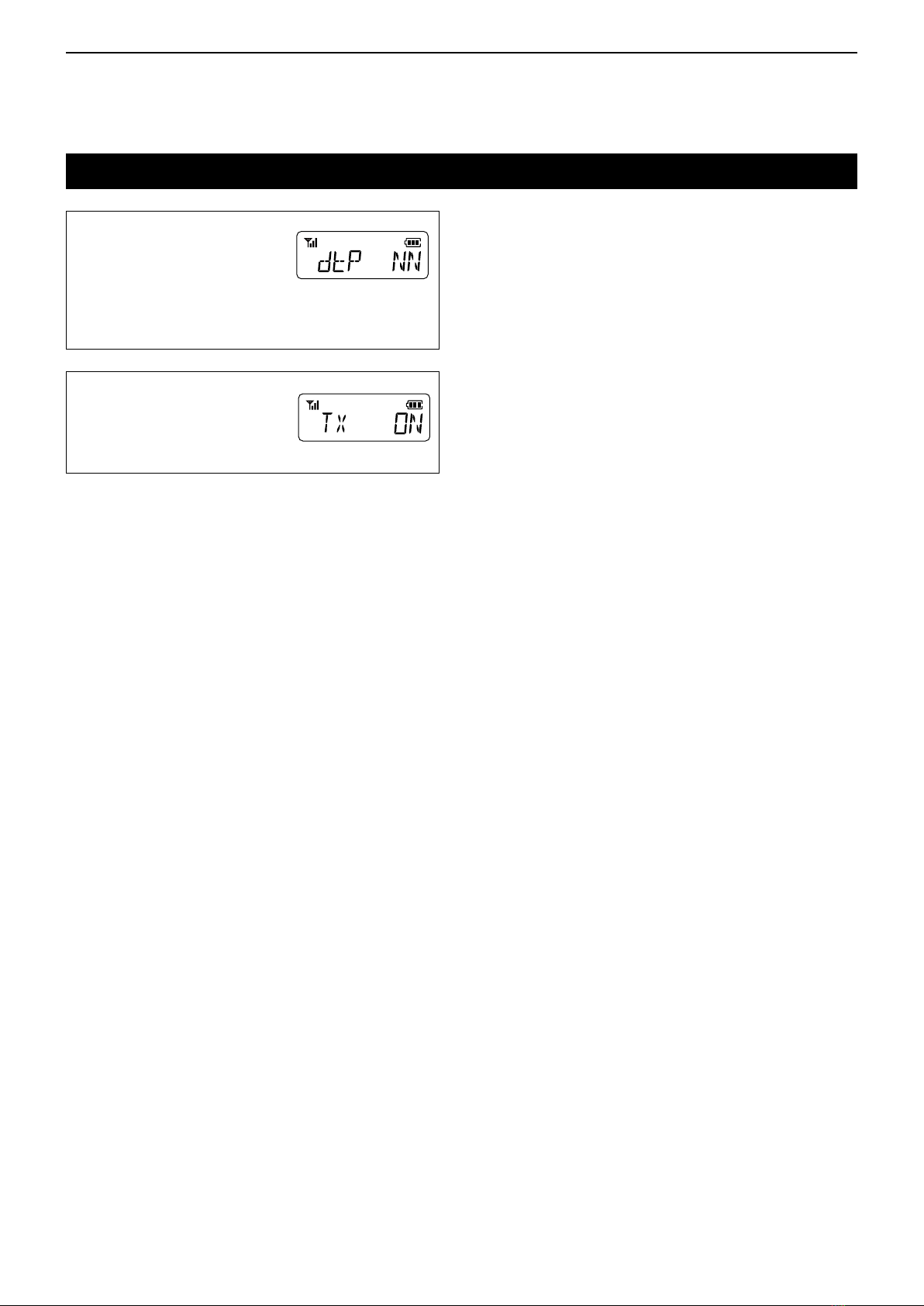
DTMF Autodial
➥Push to enter the DTMF channel selection mode.
Then, select a DTMF channel using [UP] or
[DOWN]. After selecting the channel, push this key
again to transmit the selected DTMF code.
Re-dial
➥Push to transmit the last-transmitted DTMF code.
Surveillance
➥Hold down for 1 second to turn ON the Surveillance
function.
• When the Surveillance function is ON, beeps do not
sound and the LED indicator does not light, even when
receiving a signal, or pushing a key.
➥Push to turn OFF the Surveillance function.
Siren
➥Hold down for 1 second to emit a siren.
• This function can be used for situations other than an
emergency alert, such as a security alarm.
The transceiver emits the siren until the power is turned
OFF.
Scrambler
➥Push to turn the Voice Scrambler function ON or
OFF.
Compander
➥Push to turn the Compander function ON or OFF.
• The Compander function reduces noise components
from the transmitted audio to provide clear communica-
tion.
NOTE: About the default settings of these keys, See
PANEL DESCRIPTION described in INSTRUC-
TIONS w.
NOTE: The last-transmitted DTMF code will be
cleared after turning OFF the transceiver.
NOTE: Congure a DTMF code to transmit using the
CS-G88 programming software.