4
REMOTE CONTROL
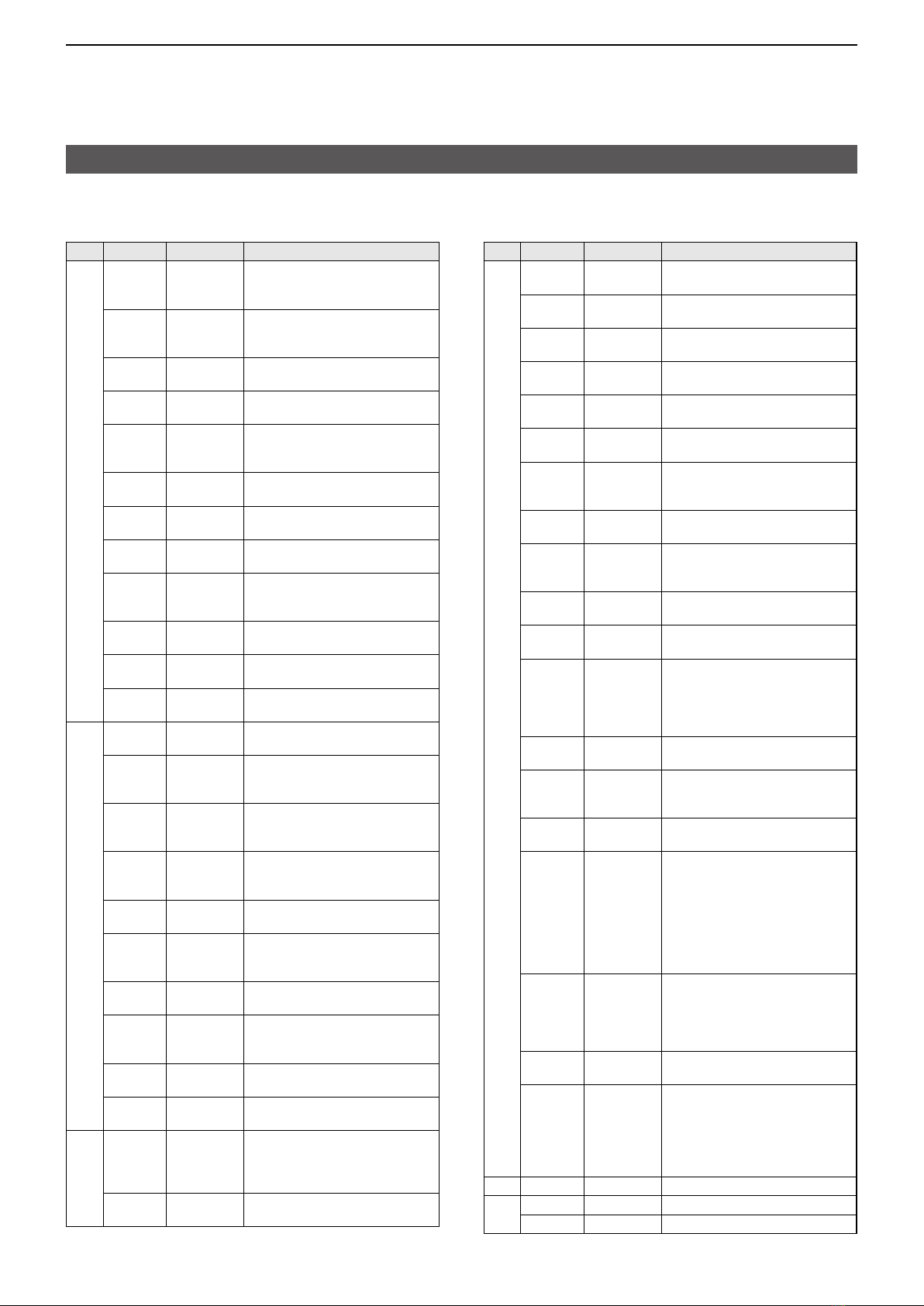
Cmd�
Sub cmd� Data Description
14* 09 0000 ~ 0255 Send/read CW pitch (5 Hz steps)
(0000=300 Hz ~ 0128=600 Hz ~
0255=900 Hz)
0A 0000 ~ 0255 Send/read the selected band’s RF
power
(0000=Minimum ~ 0255=Maximum)
0B 0000 ~ 0255 Send/read MIC gain
(0000=Minimum ~ 0255=Maximum)
0C 0000 ~ 0255 Send/read keying speed
(0000=6 WPM ~ 0255=48 WPM)
0D 0000 ~ 0255 Send/read Notch filter setting
(0000=max� Counter Clockwise ~
0128=center ~ 0255=max� Clockwise)
0E 0000 ~ 0255 Send/read the COMP level
(0000=0 ~ 0255=10)
0F 0000 ~ 0255
Send/read the Break-IN Delay setting
(0000=2�0d ~ 0255=13�0d)
12 0000 ~ 0255 Send/read NB level
(0000=0% ~ 0255=100%)
15 0000 ~ 0255 Send/read Monitor audio [MONI]
level
(0000=0% ~ 0255=100%)
16 0000 ~ 0255 Send/read the VOX gain
(0000=0% ~ 0255=100%)
17 0000 ~ 0255 Send/read the Anti VOX gain
(0000=0% ~ 0255=100%)
19 0000 ~ 0255 Send/read LCD backlight brightness
(0000=0% ~ 0255=100%)
15*101 00/01
Read noise or S-meter squelch status
(00=Close, 01=Open)
02 0000 ~ 0255 Read S-meter level
(0000=S0, 0120=S9,
0241=S9+60 dB)
05 00/01 Read various squelch (tone squelch,
and so on) status
(00=Close, 01=Open)
07 00/01 Read the OVF status
(00=OVF indicator is OFF,
01=OVF indicator is ON)
11 0000 ~ 0255 Read the Pmeter level
(0000=0% ~ 0143=50% ~ 0213=100%)
12 0000 ~ 0255 Read SWR meter level
(0000=SWR1�0, 0048=SWR1�5,
0080=SWR2�0, 0120=SWR3�0)
13 0000 ~ 0255 Read ALC meter level
(0000=Minimum ~ 0120=Maximum)
14 0000 ~ 0255 Read COMP meter level
(0000=0 dB ~ 0130=15 dB ~
0210=25�5 dB)
15 0000 ~ 0255 Read Vmeter level
(0000=0 V ~ 0075=5 V ~ 0241=16 V)
16 0000 ~ 0255 Read Imeter level
(0000=0 A ~ 0121=2 A ~ 0241=4 A)
16* 02 00 ~ 02 Send/read the Preamp
(00=OFF, 01=P�AMP1, 02=P�AMP2)
(In the 144 or 430 MHz bands,
00=OFF, 01=ON)
12 01 ~ 03 Send/read the AGC time constant
(01=FAST, 02=MID, 03=SLOW)
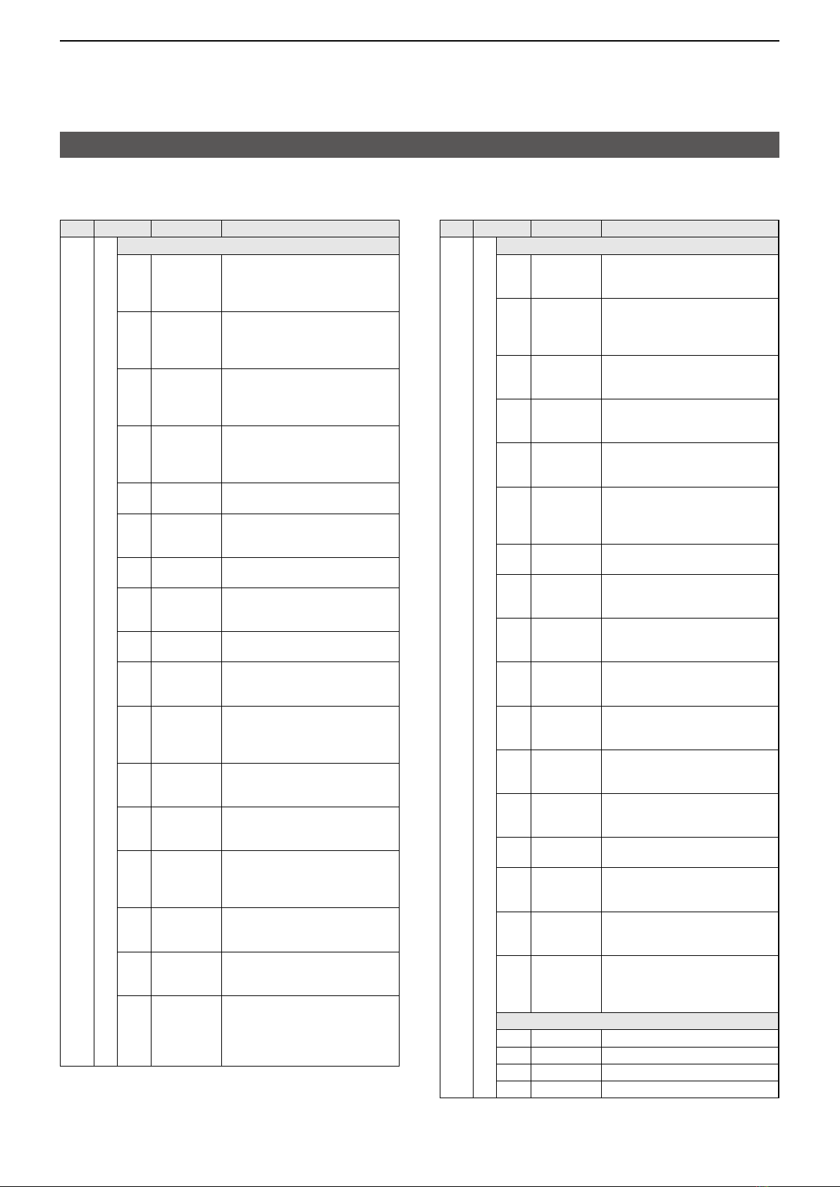
Remote control (CI-V) information
DCommand table
Cmd�
Sub cmd� Data Description
16* 22 00/01 Send/read the Noise blanker
(00=OFF, 01=ON)
40 00/01 Send/read the Noise reduction
(00=OFF, 01=ON)
41 00/01 Send/read the Auto Notch function
(00=OFF, 01=ON)
42 00/01 Send/read the Repeater tone
(00=OFF, 01=ON)
43 00/01 Send/read the Tone squelch
(00=OFF, 01=ON)
44 00/01 Send/read the Speech compressor
(00=OFF, 01=ON)
45 00/01 Send/read the Monitor [MONI]
function
(00=OFF, 01=ON)
46 00/01 Send/read the VOX function
(00=OFF, 01=ON)
47 00 ~ 02 Send/read the BK-IN function
(00=BK-IN OFF, 01=Semi BK-IN ON,
02=Full BK-IN ON)
48 00/01
Send/read the Manual Notch function
(00=OFF, 01=ON)
4B 00/01 Send/read the DTCS function
(00=OFF, 01=ON)
4F 00/01 Send/read the Twin peak filter
(00=OFF, 01=ON)
(Can be turned ON only when Mark
and Shift are set to 2125 Hz and
170 Hz, respectively)
50 00/01 Send/read the Dial lock function
(00=OFF, 01=ON)
56 00/01 Send/read DSP IF filter type in the
operating band
(00=SHARP, 01=SOFT)
57 00 ~ 02 Send/read the Manual Notch width
(00=WIDE, 01=MID, 02=NAR)
58 00 ~ 02 Send/read SSB transmit bandwidth
(00=WIDE, 01=MID, 02=NAR)
(One of following values is applied,
depending on the “COMP” status
(ON or OFF):
WIDE (Command: 1A 05 0017),
MID (Command: 1A 05 0018), or
NAR (Command: 1A 05 0019))
5B 00 ~ 02 Send/read the DSQL (Digital Call
Sign squelch)/CSQL (Digital Code
squelch) setting
(DV mode only)
(00=OFF, 01=DSQL, 02=CSQL)
5C 00 ~ 02 Send/read the GPS TX mode
(00=OFF, 01=D-PRS, 02=NMEA)
5D 00 ~ 03,
06 ~ 09
Send/read the Tone squelch function
(00=OFF, 01=TONE, 02=TSQL,
03=DTCS, 06=DTCS (T),
07=TONE (T)/DTCS (R),
08=DTCS (T)/TSQL (R),
09=TONE (T)/TSQL (R))
17*3See p� 16� Send CW messages
18 00 Turn OFF the transceiver
01*4Turn ON the transceiver