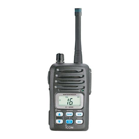
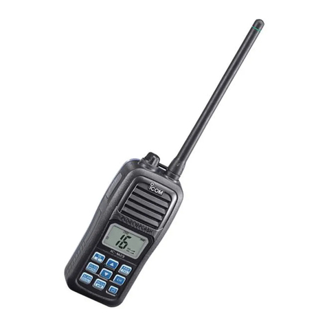
Icom IC-M73 User manual

S-14919XZ-C1
April 2013
VHF MARINE TRANSCEIVER

This service manual describes the latest technical information
for the IC-M73, IC-M73EURO VHF MARINE TRANSCEiVER,
at the time of publication.
NEVER connect the transceiver to an AC outlet or to a DC
power supply that uses more than the specified voltage. This
will ruin the transceiver.
DO NOT reverse the polarities of the power supply when con-
necting the transceiver.
DO NOT apply an RF signal of more than 20 dBm (100 mW) to
the antenna connector. This could damage the transceiver’s
front-end.
To upgrade quality, any electrical or mechanical parts
and internal circuits are subject to change without notice
or obligation.
MODEL VERSION AC ADAPTER FLEXIBLE
ANTENNA
IC-M73
USA BC-123SA
FA-S64V
EXP BC-123SE
USA-10 BC-123SA
EXP-10
BC-123SE
IC-M73EURO
EUR-01 FA-S59V
EUR
FA-S64V
UK –
FRG BC-123SE
HOL
AUS BC-123SV
EUR-11 BC-123SE FA-S59V
EUR-10
FA-S64V
UK-10 –
FRG-10 BC-123SE
HOL-10
AUS-10 BC-123SV
Be sure to include the following four points when ordering
replacement parts:
1. 10-digit Icom part number
2. Component name
3. Equipment model name and unit name
4. Quantity required
<ORDER EXAMPLE>
1110003491 S.IC TA31136FNG IC-M73 MAIN UNIT 5 pieces
8820001210 Screw 2438 screw IC-M73 Top cover 10 pieces
Addresses are provided on the inside back cover for your
convenience.
ORDERING PARTS
1. Make sure that the problem is internal before dis-assem-
bling the transceiver.
2. DO NOT open the transceiver until the transceiver is dis-
connected from its power source.
3. DO NOT force any of the variable components. Turn them
slowly and smoothly.
4. DO NOT short any circuits or electronic parts. An insulated
tuning tool MUST be used for all adjustments.
5. DO NOT keep power ON for a long time when the trans-
ceiver is defective.
6. DO NOT transmit power into a Standard Signal Generator
or a Sweep Generator.
7. ALWAYS connect a 30 dB to 40 dB attenuator between the
transceiver and a Deviation Meter or Spectrum Analyzer,
when using such test equipment.
8. READ the instructions of the test equipment thoroughly
before connecting it to the transceiver.
REPAIR NOTES
INTRODUCTION CAUTION
(IC-M73EURO)
Icom, Icom Inc. and the Icom logo are registered trademarks of Icom Incorporated (Japan) in Japan, the United States, the
United Kingdom, Germany, France, Spain, Russia and/or other countries.

TABLE OF CONTENTS
SECTION 1 SPECIFICATIONS
SECTION 2 INSIDE VIEWS
SECTION 3 DISASSEMBLY INSTRUCTION
SECTION 4 CIRCUIT DESCRIPITON
4-1 RECEIVER CIRCUITS...................................................................................... 4-1
4-2 TRANSMITTER CIRCUITS............................................................................... 4-2
4-3 FREQUENCY SYNTHESIZER CIRCUITS ....................................................... 4-3
4-4 POWER SUPPLY CIRCUITS............................................................................ 4-4
4-5 PORT ALLOCATIONS ...................................................................................... 4-4
SECTION 5 ADJUSTMENT PROCEDURES
5-1 PREPARATION ................................................................................................. 5-1
5-2 FREQUENCY ADJUSTMENT .......................................................................... 5-3
5-3 RECEIVE AND TRANSMIT ADJUSTMENT ..................................................... 5-4
SECTION 6 PARTS LIST
SECTION 7 MECHANICAL PARTS
SECTION 8 BOARD LAYOUTS
SECTION 9 BLOCK DIAGRAM
SECTION 10 VOLTAGE DIAGRAM

1 - 1
SECTION 1
.
SPECIFICATIONS
GENERAL
IC-M73 IC-M73EURO IC-M73EURO
(AUS version)
• Frequency coverage TX 156.025–157.425 MHz 156.000–161.450 MHz 156.025–157.425 MHz
RX 156.050–163.275 MHz 156.000–163.425 MHz 156.300–162.025 MHz
• Type of emission 16K0G3E
• Antenna impedance 50 Ω(nominal)
• Operating temperature range –20°C to +60°C
(–4°F to +140°F) –15°C to +55°C –10°C to +55°C
• Power supply requirement 7.4 V DC nominal (negative ground)
• Current drain
(approximately) RX 0.25 A (at maximum audio, using external 8 Ω speaker)
0.45 A (at maximum audio, using internal speaker)
TX
6.0 W 1.5 A –
5.0 W – 1.4 A
3.0 W 1.2 A
1.0 W 0.7 A
0.5 W – 0.6 A –
• Dimensions (projections not included) 52.5(W) × 125(H) × 30(D) mm; 2.0(W) × 4.9(H) × 1.2(D) inches
• Weight (approximately) 280 g; 9.9 oz (Including only BP-245N)
320 g; 11.3 oz (Including BP-245N, FA-S64V and MB-103)
TRANSMITTER
• Output power High 6 W 6 W (1 W for [FRG]) 5 W
Middle 3 W
Low 1 W 1 W (0.5 W for [FRG]) 1 W
• Modulation Variable reactance frequency modulation
• Maximum frequency deviation ±5 kHz
• Frequency error ±10 ppm ±1.5 kHz ±10 ppm
• Spurious emissions –68 dBc (typical) 0.25 µW
• Adjacent channel power 70 dB
• Audio harmonic distortion 10% (at 60% deviation)
• FM hum and noise 40 dB
• Audio frequency response +1 dB to –3 dB of 6 dB octave from 300 Hz to 3000 Hz
• Microphone impedance 2 kΩ
RECEIVER
• Intermediate frequency 1st 21.7 MHz 2nd 450 kHz
• Sensitivity –13 dBµ (0.22 µV)
(at 12 dB SINAD) typical
–4 dBµ emf (at 20 dB SINAD)
typical
–5 dBµ emf (at 20 dB
SINAD) typical
• Squelch sensitivity (at threshold) –9 dBµ (0.35 µV) typical –5 dBµ emf typical –6 dBµ emf typical
• Adjacent channel selectivity 70 dB typical 70 dB 65 dB
• Spurious response 70 dB typical 70 dB 65 dB
• Intermodulation rejection ratio 70 dB typical 68 dB 65 dB
• Hum and Noise 40 dB
• Audio frequency response +1 dB to –3 dB of –6 dB octave from 300 Hz to 3000 Hz
• Audio output power
(at 10% distortion with an 8 Ωload)
0.35 W typical (External) 0.2 W (External)
0.7 W typical (Internal) 0.7 W typical (Internal) at 1 kHz
• Output impedance (audio) 8 Ω
All stated specifications are subject to change without notice or obligation.

2 - 1
SECTION 2
.
INSIDE VIEWS
• MAIN UNIT
IF IC
(IC170)
2ND IF FILTER
(FI170)
EEPROM
(IC340)
RESET IC
(IC341)
BUFFER
(IC364)
BUFFER
(Q350)
AF MUTE
(IC430)
MIC AMP
(IC200)
FLASH ROM
(IC501)
AFV LINE CONTROL
(Q231)
AFV LINE CONTROL
(Q401)
AF PWR AMP
(IC280)
AF SW
(IC260)
AF PWR AMP
(IC401)
NOISE CANCELLER
PLAYBACK/RECORD IC
(IC500)
AFV LINE CONTROL
(Q230)
CPU 5V
(IC220)
CPU
(IC360)
BACKLIT LED DRIVER
(Q240)
CPU CLOCK
(X480)
AF MUTE
(IC504)
DISCRIMINATOR
(X170)
LPF
(IC432)
+5 V REGULATOR
(Q221)
+5 V REGULATOR
(Q225)

2 - 2
VCO
• RF UNIT
(TOP VIEW)
• RF UNIT
(BOTTOM VIEW)
TX MUTE SW
(Q351)
RF AMP
(Q90)
VCC LINE
CONTROLLER
(Q480)
1st MIXER
(Q150)
PLL IC
(IC1)
+3.3 V REGULATOR
(IC2)
BUFFER
(Q3)
+5 V REGULATOR
(Q222)
REFERENCE
FREQUENCY
OSCILLATOR
(X1)
APC AMP
(IC50)
1ST IF AMP
(Q151)
BPF
(FI150)
BPF
(FI151)

3 - 1
SECTION 3
.
DISASSEMBLY INSTRUCTION
1. Removing the Front panel
1) Remove 6 screws from the rear panel.
2) Disconnect the speaker cable from the MAIN UNIT
and remove the front pannel form rear. (The lock
plate is simultaneously come off.)
J251
MAIN UNIT
REAR PANEL
Screw×4
Screw×2
J251
MAIN UNIT
MAIN UNIT
CHASSIS
Screw×5
J251
J251
MAIN UNIT
SPEAKER
CABLE
LOCK PLATE
FRONT PANEL
CHASSIS
J251
MAIN UNIT
MAIN UNIT
RF
UNIT
J300
FLAT
CABLE
CHASSIS
2. Removing the MAIN UNIT
1) Remove 5 screws from the MAIN UNIT.
2) Disconnect 2 flat cables from the MAIN UNIT.
3) Remove the MAIN UNIT from the CHASSIS.
BE CAREFUL about the flat cable and connector when
separating the MAIN UNIT from the CHASSIS.

4 - 1
J251
MAIN UNIT
RF UNIT
UNSOLDER
Solder
remover
CHASSIS
J251
MAIN UNIT
CHASSIS
Screw×3
RF UNIT
3. Removing the RF UNIT
1) Unsolder total of 7 points.
2) Remove 3 screws from the RF UNIT.
3) Remove the RF UNIT from the CHASSIS.

4 - 1
SECTION 4
.
CIRCUIT DESCRIPTION
1st IF signal
to the FM IF IC
(MAIN UNIT; IC170, pin 16)
(Q151) 21.7 MHz
1st IF signal
Received signals
from the RF circuits
1st IF amp
1st mixer
(Q150)
signals from the VCO
• 1st IF CIRCUITS
FI150, FI151
LPF
BPF
2 BPF’s
Mixer
Quadrature
detector
1st IF signal from the IF amplifier (RF UNIT: Q151)
16
Noise
detector
R5V
X170
1110
IF IC
(IC170)
Filter
amp.
Limiter
amp.
Demodulated signal
to the AF circuits
• 2ND IF AND DEMODULATOR CIRCUITS
9
(IC190)
19
18
“NOISV” signal to the CPU (IC360, pin 32)
“RSSIV” signal to the CPU (IC360, pin 33)
1412
21.25 MHz
2
17
X1
21.25 MHz
8 7 35
FI170 LPF
BPF PLL IC
(IC1)
RF UNIT
SQLO
SQLI
2NDLO
D/A
converter
4-1 RECEIVE CIRCUIT
• ANTENNA SWITCH (RF UNIT)
The received signal from the antenna connector are passed
through the low-pass filter (LPF; L81, L82, C83−C86 and
C89) and the antenna switch (D90), which toggles the re-
ceive (RX) line and transmit (TX) line.
While transmitting, the voltage on the T5V line is applied to
D52 and D90, and these are ON. Thus the TX line is con-
nected to the antenna, and RX line is connected to the
ground to prevent transmit signal entering.
While receiving, no voltage is applied to D52 and D90, and
these are OFF. Thus the TX line is disconnected from the
antenna to prevent received signal entering, and RX line is
disconnected from the ground and L90, C90 and C91 com-
pose a two-staged LPF, which guides received signal to the
RX circuits.
The received signal is applied to the RF circuits.
• RF CIRCUITS (RF UNIT)
The RF circuit amplifies received signal within the frequency
coverage. The received signal is filtered at the bandpass fil-
ter (BPF) and amplified at the RF amplifier.
The received signal from the antenna switch is passed
through the two-staged tunable BPFs (D92, L92, C95, C97
and D93, L93, C99, C100) to filter out unwanted signal. The
filtered signal is applied to the RF amplifier (Q90). The am-
plified signal is then applied to the 1st mixer (Q150), through
another two-staged tunable BPF (D130, L96, C110, C112
and D131, L97, C114, C115).
• 1st IF CIRCUITS (RF UNIT)
The received signal is converted into the 1st IF signal, and
amplified at the 1st IF circuits.
The amplified received signal from the RF circuits are ap-
plied to the 1st mixer (Q150), and mixed with the 1st local
oscillator (LO) signal from the VCO (Q21, Q22, D20−D22),
resulting in the 21.7 MHz 1st IF signal.
The converted 1st IF signal is passed through two 1st IF
filters (FI150 and FI151) to filter out unwanted signal, and
then applied to the 1st IF amplifier (Q151). The amplified 1st
IF signal is applied to the IF IC (MAIN UNIT: IC170, pin 16).
• 2nd IF AND DEMODULATOR CIRCUITS
(MAIN UNIT)
The 1st IF signal is converted into the 2nd IF signal, and de-
modulated.
The 1st IF signal from the 1st IF circuits is applied to the 2nd
IF mixer in the IF IC (IC170) and mixed with the 21.25 MHz
2nd LO signal from the reference oscillator (RF UNIT: IC1,
X1), resulting in the 450 kHz 2nd IF signal.
The converted 2nd IF signal is output from pin 3, and passed
through the 2nd IF filter (FI170) to suppress sideband noise.
The filtered signal is amplified by the limiter amplifier (IC170,
pin 5) and FM-demodulated by the quadrature detector with
the discriminator (X170), and then output from pin 9. The de-
modulated AF signal is applied to the AF circuits.

4 - 2
Power
amp.
APC
amp.
Buffer
amp.
+
–
VCC
• APC CIRCUIT
To the anntena
T5V
PCON
LOW
TXMS
from the TX/RX switch (D50)
Q53
Pre-drive
amp.
Q50
IC50
3
1
4
Q351
Q54
LPF
ANT
SW
Q100
D91
D52
T5V
• AF CIRCUITS (MAIN UNIT)
The demodulated AF signal from the demodulator circuits is
amplified and filtered in AF amplifier circuits.
The demodulated AF signal from the IF IC (IC170, pin 9) is
passed through the AF mute switch (IC430, pins 10, 11),
LPF (IC432) and variable register (VR UNIT: R801) which
adjusts the AF signal in level.
The level-adjusted AF signal is passed through the de-em-
phasis circuit (R286, C280 and C285) to obtain −6 dB of au-
dio characteristic, and passed through the AF switch (IC260,
pins 1, 6), and then applied to the AF power amplifier (IC401,
pin 7) to obtain 0.6 W of output power. The power-amplified
AF signal is then output from pin 1, and applied to the inter-
nal speaker, through J251.
When an external speaker-microphone or headset is at-
tached to the [SP MIC] connector (MIC UNIT: J416), the
de-emphasized AF signal is passed through the AF switch
(IC260, pins 1, 7) and applied to the AF power amplifier
(IC280, pin 4) to obtain 0.2 W of output power. The power-
amplified AF signal is output from pin 10, and then applied
to the external speaker, through the [SP MIC] connector (MIC
UNIT: J416).
• SQUELCH CIRCUIT (MAIN UNIT)
The squelch mutes the AF output signal when no RF signal
is received. By detecting noise components in the demodu-
lated AF signal, the squelch circuit toggles the AF power
amplifier ON and OFF.
A portion of the demodulated AF signal from the IF IC
(IC170, pin 9) is applied to the D/A converter (MAIN UNIT:
IC190, pin 18) for level adjustment (squelch threshold ad-
justment). The level-adjusted AF signal is output from pin 19,
and passed through the noise filter (R174−R176, C179 and
C180). The only filtered noise signal is applied to the noise
amplifier in the IF IC (IC170, pins 7, 8).
The amplified noise components are converted into the
pulse-type signal at the noise detector section, and output
from pin 19 as the “NOISV1” signal. The signal is amplified
by the Amplifier (IC432) and then applied to the CPU (IC360,
pin 32), and the CPU outputs “AFVS” signal from pin 100,
depending on the “NOISV1” signal level, to the AF power
regulator (Q230, Q231 and Q401), which turns the AF power
amplifiers (IC280 and IC401) ON or OFF.
4-2 TRANSMIT CIRCUITS
• MICROPHONE AMPLIFIER CIRCUITS
(MAIN UNIT)
The AF signal from the microphone (MIC signal) is filtered
and level-adjusted at microphone amplifier circuits.
The AF signal from the microphone is passed through the
MIC mute switch (IC430A, pins 1, 2).
While an external microphone is connected to the [SP MIC]
connector (MIC UNIT: J416), the MIC mute switch shuts out
the MIC signal from the internal microphone (MC1).
The AF signal from the MIC mute switch (IC430A, pins 1, 2)
is passed through another AF mute switch (IC430B,
pins 3, 4), and applied to the microphone amplifier (IC200B,
pins 6, 7). The amplified MIC signal is passed through AF
mute switch (IC430, pins 8, 9), and is applied to the D/A con-
verter (IC190) and adjusted in level (=deviation adjustment).
The level-adjusted MIC (MOD) signal is passed through the
pre-emphasis circuit (R201 and C450) to obtain +3 dB of
characteristic. The pre-emphasized signal is then applied to
the limiter amplifier (IC200D, pins 13, 14), which limits the
amplitude of the MIC signal to prevent over deviation.
The amplitude-limited MIC signal is then passed through
the splatter filter (IC200A, pins 1, 3), which suppresses the
3 kHz and higher audio components, and then applied to the
modulation circuit (RF UNIT: D20).
• MODULATION CIRCUIT (RF UNIT)
The modulation circuit modulates the VCO oscillating signal
using the AF signal from the microphone.
The MIC signal from the microphone amplifier circuits is ap-
plied to the D20, and modulate the VCO oscillating signal by
changing the reactance of D20. The modulated VCO output
signal is buffer-amplified by Q23 and Q24, and then applied
to transmit amplifier circuits, through the TX/RX switch (D50).
• TRANSMIT AMPLIFIERS (RF UNIT)
The VCO output signal is amplified to the transmit output
power level by the transmit amplifiers.
The transmit signal from the TX/RX switch (D50) is ampli-
fied by the buffer amplifier (Q50), and then further amplified
by the pre-driver (Q53) and power amplifier (Q54) to the
transmit output level. The power-amplified transmit signal is
passed through the TX power detector of APC circuit (D91),
antenna switch (D52) and LPF (as a harmonic filter; L81,
L82, C83−C86 and C89), before being applied to the an-
tenna connector (CHASSIS: J1).
4 - 3
DATA interface
Prescaler
Phase
detector
Loop
filter
Reference
counter
Programmable
counter
Charge
pump
Buffer
Q23
Buffer
Q24
Buffer
Q25 to the TX/RX switch (D50, D51)
Q21, Q22, D20–D22
VCO
LPF
To the FM IF IC
(MAIN UNIT: IC170, pin 2)
3
13
7
19
17
15
16
“PLST”
“UNLK”
• PLL CIRCUITS
“SCK”
“SDATA”
X1
4
5
PLL IC (RF UNIT; IC1)
LPF
:
• APC CIRCUIT (RF UNIT)
The APC (Automatic Power Control) circuit stabilizes trans-
mit output power to prevent transmit output power level
change which is caused by load mismatching or heat effect,
etc. The APC circuit also selects transmit output power from
high, middle and low power.
The power detector circuits (D91) detects the transmit output
and converts it into DC voltage, which is in proportion to the
transmit output power level. The detected voltage is applied
to the differential amplifier (IC50, pin 3). The transmit power
setting voltage “PCON” is also applied to another input ter-
minal (pin 1) as the reference voltage.
The differential amplifier compares the detected voltage and
reference voltage, and the voltage difference is output from
pin 4. The output voltage controls the bias of the pre-drive
(Q53) and power AMP (Q54) to adjust the gain of them for
stable transmit output power.
The transmit power is set by the changing reference voltage
"PCON" and "TCON/LOW."
4-3 FREQUENCY SYNTHESIZER
• VCO CIRCUIT (RF UNIT)
The VCO (Q21, Q22, D20−D22) generates the both of trans-
mit signal and LO signal for the 1st IF conversion. The VCO
output signal is buffer-amplified by Q23 and Q24.
While transmitting, the VCO output signal is applied to the
transmit amplifier circuit, through the TX/RX switch (D50).
While receiving, the VCO output signal is applied to the 1st
mixer (Q150), through the TX/RX switch (D51) and the BPF
(L26 and C122), to be mixed with the received signal to pro-
duce the 21.7 MHz 1st IF signal.
A portion of the VCO output is applied to the PLL IC (IC1,
pin 19), through the buffer amplifier (Q25) and LPF (L20,
C21 and C22).
• PLL CIRCUIT (RF UNIT)
The PLL circuit provides stable oscillation of the transmit
frequency and receive 1st LO frequency. The PLL output
frequency is controlled by the divided ratio (N-data) from the
CPU.
The buffer-amplified signal from the LPF (L20, C21 and C22)
is applied to the PLL IC (IC1, pin 16). The applied signal is
divided by the prescaler and programmable counter, accord-
ing to the “SDATA (SDATAO)” signal from the CPU (MAIN
UNIT: IC360, pin 10). The divided signal is phase-compared
with the reference frequency signal, which is divided by ref-
erence counter, at the phase detector.
The phase difference is output from pin 13 as a pulse type
signal after being passed through the charge pump. The
output signal is converted into the DC voltage (lock voltage)
by passed through the loop filter (R10, R22, C11, C13 and
C24). The lock voltage is applied to the variable capacitors
(D22) of the VCO (Q21, Q22, D20−D22) and locked to keep
the VCO frequency constant.
If the oscillated signal drifts, its phase changes from that of
the reference frequency, causing a lock voltage change to
compensate for the drift in the VCO oscillating frequency.

4 - 4
4-4 POWER SUPPLY CIRCUITS
Line
name Description
VCC The same voltage as attached battery pack.
CPU5V
Common 5 V converted from VCC line by the
CPU5V regulator (IC220).
The voltage is applied to the CPU (IC360), Reset
IC (IC341), EEPROM (IC340), etc.
5V
Common 5 V converted from VCC line by the 5V
regulator (Q223−Q225) controlled by "M5VS" sig-
nal from the CPU (IC360, pin 101).
The voltage is applied to the backlight LED'S
(DS240−DS243, DS250−DS253), D/A converter
(RF UNIT: IC190), PLL IC (RF UNIT: IC1), etc.
V5V
Common 5 V converted from VCC line by the V5V
regulator (RF UNIT: Q220).
The voltage is applied to the VCO (RF UNIT:
Q21, Q22, D20−D22)
R5V
Receive 5 V controlled by the R5V regulator (Q221)
using "R5VS" signal from the CPU (IC360, pin 95).
The voltage is applied to the receive circuits (RF
UNIT: 1st mixer (Q150), 1st IF amplifier (Q151),
RF amplifier (Q90), etc.).
T5V
Transmit 5 V controlled by the T5V regulator (RF
UNIT: Q222) using "T5VS" signal from the CPU
(IC360, pin 13).
The controlled voltage is applied to the transmit
circuits (RF UNIT: differential amplifier (IC50), pre-
driver (Q53), power amplifier (Q54), microphone
amplifier (IC8), etc.).
Pin
No.
Port
Name Description I/O
1 BEEP Beep sound to the AF circuits. O
4DAST
(DAST)
Strobe signal to the D/A converter (IC190,
pin 3). O
5PLSTB
(PLST)
PLL strobe signal to the PLL IC (RF UNIT:
IC1, pin 8). O
11 SCLK
(SCK)
Serial clock signal to the PLL IC (RF UNIT:
IC1, pin 6) and D/A converter (IC190,
pin 4).
O
12 V5VS
V5V regulator (Q220) control signal.
"High"= While in the power save mode (The
VCO (Q21, Q22, D21−D23) is
not activated).
O
13 T5VS
T5V regulator (RF UNIT: Q222) control
signal.
"Low"= While transmitting.
"High"= While receiving or in the power
save mode.
O
14 LCDS
LCD contrast select signal.
"Low"= While "Bright" is selected.
"High"= While "Dark" is selected.
O
15 LEDS
Backlight LED (DS240−DS243,
DS250−DS253) control signal to the LED
driver (Q240).
"High"= While the backlight is ON.
O
25 RES Reset signal from the reset IC (IC341,
pin 4). I
27†WDECV Demodulated weather alart (WX) signal
from the AF circuit. I
28 EXDET External connection detect. I
29 VOXT
Voice input detection from the VOX
amplifier (IC431, pin 7) for the VOX
operation.
I
30 BATTV Remaining battery voltage. I
31 TDETV TX power level sensing voltage from the
transmit power detector (RF UNIT: D91). I
32 NOISV Noise level from the IF IC (IC170, pin 14). I
33 RSSIV RSSI signal from the IF IC (IC170, pin 12). I
34 LOINV Lock voltage. I
35 TEMPV Temperture sensing voltage. I
36 WET Water leaking detection. I
93 ESCK Serial clock to the EEPROM (IC501, pin 6). O
94 ESDA Serial data to the EEPROM (IC501, pin 5). O
95 R5VS R5V line regulator (Q221) control.
"High"= While receiving. O
96 EXPTT External PTT.
"High"= The external PTT is pushed. I
97 TXMS Transmit mute switch (Q351) control.
"Low"= While receiving. (Mute) O
98 DETMS AF mute switch (IC430, pin 12) control.
"High"= While the squelch is open. O
100 AFVS
AF power amplifier power supply switch
control.
"High"= While the amplifier is activated.
O
102 PTTIN Input port for [PTT]. (RF UNIT: S250)
"High": Pushed. I
104 BTYPE Battery type detection. I
105 PTTM
AF mute switch (IC430, pin 13) control.
"High": While transmitting.
"Low": While transmitting with VOX
function.
O
4-5 PORT ALLOCATIONS
• CPU (MAIN UNIT: IC360)

4 - 5
Pin
No.
Port
Name Description I/O
106 MIC1/
SPCTRL
• While transmitting:
MIC gain controller (Q450 and Q451)
control.
(The microphone sensitivity is
determinded by the combination of
output voltage of "MIC1−MIC3.")
• While receiving:
Analog switch (IC430, pins 6, 12) control.
O
107 MIC2/
AFVCTRL
• While transmitting:
MIC gain controller (Q450 and Q451)
control.
• While receiving:
AF amplifier power supply circuit (Q230,
Q231, Q401 and Q540) control.
O
108 MIC3/
BPCTRL
• While transmitting:
MIC gain controller (Q450 and Q451)
control.
• While recseiving:
AquaQuake function control.
"Low": AquaQuake function is activated.
O
109 SQL
Input port for the [SQL] key (RF UNIT:
S250).
"Low": While the [SQL] key is pushed.
I
110 UP
Input port for the [ ] key (MAIN UNIT:
S321).
"Low": When the [ ] key is pushed.
I
111 DOWN
Input port for the [ ] key (MAIN UNIT:
S322).
"Low": When the [ ] key is pushed.
I
112 CH/WX
Input port for the [CH/WX] key (MAIN
UNIT: S324).
"Low": When the [CH/WX] key is pushed.
I
113 16
Input port for the [16/C] key (MAIN UNIT:
S320).
"Low": When the [16/C] key is pushed.
I
114 SCAN
Input port for the [SCAN] key (MAIN UNIT:
S324).
"Low": When the [SCAN] key is pushed.
I
115 H/L
Input port for the [H/L] key (MAIN UNIT:
S329).
"Low": When the [H/L] key is pushed.
I
117 VOXM AF mute switch (IC430, pin 5) control.
"High": While transmitting. O
119 UNLK
PLL unlock signal from the PLL IC (IC1,
pin 5).
"High": While the PLL is unlocked.
I
• D/A CONVERTER (RF UNIT: IC190)
Pin
No.
Port
Name Description
2 MODC Deviation adjustment.
3 FCON Reference frequency adjustment.
10 PCON Transmit power setting voltage.
11 ATTS
Attenuator (RF UNIT: D94) switching signal.
"High"=The attenuator (RF UNIT: D94) is acti-
vated.
15 LOW
Transmit power setting signal.
"High"=TX power [High] or [Mid] is selected.
"Low"=TX power [LOW] is selected.
22 TCON/
LOW
• While receiving:
BPFs (RF UNIT: D130, L96, C110, C112 and
D131, L97, C114, C115) tuning voltage.
• While transmitting:
Transmit power setting voltage.
• CPU (MAIN UNIT: IC360) (continued)

5 - 1
SECTION 5
.
ADJUSTMENT PROCEDURE
¤ JIG CABLE
EQUIPMENT GRADE AND RANGE EQUIPMENT GRADE AND RANGE
Cloning software ADJ-M73 ADJUSTMENT SOFTWARE
(Revision 1.0 or later) JIG cable Modified OPC-478UC and OPC-922
(See the illust below)
RF power meter
(50 Ω terminated)
Measuring range : 0.1–10 W
Frequency range : 100–300 MHz
SWR : Less than 1.2 : 1
Frequency counter
Range : 0.1–300 MHz
Accuracy : ±1 ppm or better
Input level : Less than 1 mW
Modulation
Analyzer
Frequency range : 30–300 MHz
Measuring range : 0 to ±10 kHz Standard signal
generator (SSG)
Frequency range : 0.1–300 MHz
Output level : –20 dBµ to 90 dBµ
(–127 to –17 dBm)
AC millivoltmeter Measuring range : 10 mV to 10 V
Oscilloscope Frequency range : DC–20 MHz
Measuring range : 0.01–20 V Attenuator Attenuation : 30 dB
Capacity : More than 10 W
Audio generator
(AG)
Frequency range : 300–3000 Hz
Output level : 1–500 mV External speaker Input impedance : 8 Ω
Capacity : More than 1 W
¤ REQUIRED EQUIPMENTS
5-1 PREPARATION
OPC-478UC WHITE (MIC)
(MIC line)
(SP line)
BLUE (CLONE)
SHIELD (GND)
(CLONE line)
OPC-922 To the transceiver
RED (AFOUT)
To audio generator/AC millivoltmeter
To SINAD meter/speaker
33 k
Ω
PTT

5 - 2
¤ CONNECTION
Standard signal generator
–20 to 90 dBµ
(–127 dBm to –17 dBm)
FM
deviation meter
SINAD meter
Speaker (8 Ω)
Audio generator
AC millivoltmeter
to the antenna connector
Attenuator
30 dB or more
RF power meter
0.1–10 W/50 Ω
Frequency
counter
DO NOT transmit while
an SSG is connected to
the antenna connector.
To CLONE line
(BLACK)
To MIC line
(WHITE)
To SP line
(RED)
JIG cable
PC
to USB port
to RS-232C port
OPC-478 (RS-232C type)
OPC-478UC (USB type)
OPC-922
¤ ADJUSTMENT UTILITY
ADJUSTMENT CONDITION
REFERENCE FREQUENCY
TX OUTPUT POWER
FM MODULATION
RX SENSITIVITY
SQUELCH
VOX

5 - 3
5-2 SOFTWARE ADJUSTMENT (FREQUENCY ADJUSTMENTS)
1) Select an adjustment item using [↑]/[↓] on the PC's keyboard.
2) Set or modify the adjustment value as specified using [←]/[→] on the PC's keyboard, and then push [ENTER].
• I/O Check window
(The values shown above are exsample only.
Each transceiver has own values.)
Lock voltage
appears here
* * *
ADJUSTMENT ADJUSTMENT CONDITION MEASUREMENT VALUE
UNIT OPERATION
PLL LOCK
VOLTAGE
(Verify)
1 • Operating CH. : 16
• Receiving
PC
screen
Click the "I/O check button"
on the ADJ-M73's screen (see
page 5-3) to open the I/O check
window as below.
1.55–2.65 V
(Verify)
2 • Operating CH. : 16
• Connect a dummy load or RF power
meter to the antenna connector.
• Transmitting
REFERENCE
FREQUENCY
[Ref Freq]
1 • Operating CH. : 16
• Connect the RF power meter or a 50 Ω
dummy load to the antenna connector.
• Transmitting
Top
Panel
Loosely couple the frequency
counter to the antenna conector.
156.8000 MHz

5 - 4
ADJUSTMENT ADJUSTMENT CONDITION MEASUREMENT VALUE
UNIT OPERATION
RECEIVE
SENSITIVITY
[BPF T1]
[BPF T2]
1 • Operating CH. : 16
• Connect the SSG to the antenna
connector, and then set it as;
Frequency : 156.8000 MHz
Level : +30 dBu* (–77 dBm)
Modulation : 1 kHz
Deviation : ±3.0 kHz
• Receiving
Top
pannel
Put the cursor on the [BPF
ALL Sweep] on the ADJ-
M73's screen, and push the
[ENTER] key.
Automatic
adjustment
SQUELCH
LEVEL
[SQL Threshold]
“RECEIVE SENSITIVITY” must be adjusted before "SQUELCH LEVEL" is adjusted. Otherwise,
"SQUELCH LEVEL" will not be properly adjusted.
1 • Operating CH. : 16
• Connect the SSG to the antenna
connector, and then set it as;
Frequency : 156.8000 MHz
Level* : –12dBu (–119 dBm)*¹
–11 dBu (–118 dBm)*²
Modulation : 1 kHz
Deviation
: ±3.0 kHz
• Receiving
Top
panel
Push the [ENTER] key on the
keyboad of the connected PC.
Automatic
adjustment
[SQL Tight] 2•Set the SSG as;
Frequency : 156.8000 MHz
Level* : –4 dBu (–111 dBm)*¹
–3 dBu (–110 dBm)*²
TRANSMIT
OUTPUT POWER
[RF Power (High)]
1 • Operating CH. : 16
• RF power : High
• Transmitting
Top
panel
Connect the RF power meter
to the antenna connector.
5.6 W
(Except [AUS], [AUS-1])
4.7 W
([AUS], [AUS-1])
[RF Power (Mid-
dle)]
2 • Operating CH. : 16
• RF power : Middle
• Transmitting
3.0 W
[RF Power (Low)] 3 • Operating CH. : 16
• RF power : Low
• Transmitting
0.75 W
[RF Power (E-Low)]
4 • Operating CH. : 16
• RF power : Low
• Transmitting
0.45 W
FM DEVIATION
[MOD]
1 • Operating CH. : 16
• Set the FM deviation meter as;
HPF : OFF
LPF : 20 kHz
De-emphasis : OFF
Detector : (P–P)/2
• Connect the audio generator to
the [SP/MIC] jack, through OPC-
922, and then set it as;
Frequency : 1 kHz
Waveform : Sin
Level : 25 mV rms
• Transmitting
Top
panel
Connect the FM deviation me-
ter to the antenna con-nector,
through the attenuator.
±4.30–4.40 kHz
5-3 SOFTWARE ADJUSTMENT (RECEIVE AND TRANSMIT)
1) Select an adjustment item using [↑]/[↓] on the PC’s keyboard.
2) Set or modify the adjustment value as specified using [←]/[→] on the PC’s keyboard, and then push [ENTER].
*The output level of the standard signal generator (SSG) is indicated as the SSG's open circuit.
*¹; For [USA], [EXP] and [AUS] versions.
*²; Except [USA], [EXP] and [AUS] versions.

Eqv.= This component is equivalent to the REF No. component listed above, and
may be substituted on parts orders and repairs.
6-1
SECTION 6
.
PARTS LIST
IC170 1110008140 S.IC GT3136 <SEI> B 51.2/33.0
IC190 1110007550 S.IC R2A20178NP B 51.4/11.6
IC200 1110006350 S.IC LM2902PWR B 29.7/33.6
IC220 1180003830 S.REG NJU7772F05-TE1-#ZZZB B 63.3/6.6
IC260 1130009981 S.IC TC7W53FK(TE85LF) B 16.6/4.9
IC280 1110007850 S.IC TA7368PL-R10-R <SLVJ> B 31.8/8.0
IC340 1130015560 S.IC S-24C64CI-T8T1U3 B 66.7/37.8
IC341 1110007620 S.IC NJU7704F3-42A-TE1-#ZZZB B 73.9/34.8
IC360 1140016550 S.IC UPD780338GC-519-9EB-A B 74.3/12.7
IC364 1130016110 S.IC TC7WH14FK(TE85LF) B 78.4/36.5
IC401 1110002420 S.IC NJM2073M-TE1-#ZZZB B 9.5/3.8
IC430 1130011770 S.IC CD4066BPWR B 17.8/36.9
IC431 1110006380 S.IC LM2904PWR B 15.9/31.3
IC432 1110006380 S.IC LM2904PWR B 34.3/20.1
IC500 1190003590 S.IC LC703200AW-8C01-H [USA-10] B 21.4/16.4
1190003590 S.IC LC703200AW-8C01-H [EXP-10]
1190003590 S.IC LC703200AW-8C01-H [EUR-11]
1190003590 S.IC LC703200AW-8C01-H [EUR-10]
1190003590 S.IC LC703200AW-8C01-H [UK-10]
1190003590 S.IC LC703200AW-8C01-H [FRG-10]
1190003590 S.IC LC703200AW-8C01-H [HOL-10]
1190003590 S.IC LC703200AW-8C01-H [AUS-10]
IC501 1130016740 S.IC LE25U40CMC-AH [USA-10] B 16.3/25.7
1130016740 S.IC LE25U40CMC-AH [EXP-10]
1130016740 S.IC LE25U40CMC-AH [EUR-11]
1130016740 S.IC LE25U40CMC-AH [EUR-10]
1130016740 S.IC LE25U40CMC-AH [UK-10]
1130016740 S.IC LE25U40CMC-AH [FRG-10]
1130016740 S.IC LE25U40CMC-AH [HOL-10]
1130016740 S.IC LE25U40CMC-AH [AUS-10]
IC502 1180003980 S.REG XC6221A332MR-G [USA-10] B 23.5/27.0
1180003980 S.REG XC6221A332MR-G [EXP-10]
1180003980 S.REG XC6221A332MR-G [EUR-11]
1180003980 S.REG XC6221A332MR-G [EUR-10]
1180003980 S.REG XC6221A332MR-G [UK-10]
1180003980 S.REG XC6221A332MR-G [FRG-10]
1180003980 S.REG XC6221A332MR-G [HOL-10]
1180003980 S.REG XC6221A332MR-G [AUS-10]
IC503 1180004200 S.REG XC6221A152MR-G [USA-10] B 27.9/27.0
1180004200 S.REG XC6221A152MR-G [EXP-10]
1180004200 S.REG XC6221A152MR-G [EUR-11]
1180004200 S.REG XC6221A152MR-G [EUR-10]
1180004200 S.REG XC6221A152MR-G [UK-10]
1180004200 S.REG XC6221A152MR-G [FRG-10]
1180004200 S.REG XC6221A152MR-G [HOL-10]
1180004200 S.REG XC6221A152MR-G [AUS-10]
IC504 1130011741 S.IC TC7W66FK(TE85LF) [USA-10] B 32.2/26.2
1130011741 S.IC TC7W66FK(TE85LF) [EXP-10]
1130011741 S.IC TC7W66FK(TE85LF) [EUR-11]
1130011741 S.IC TC7W66FK(TE85LF) [EUR-10]
1130011741 S.IC TC7W66FK(TE85LF) [UK-10]
1130011741 S.IC TC7W66FK(TE85LF) [FRG-10]
1130011741 S.IC TC7W66FK(TE85LF) [HOL-10]
1130011741 S.IC TC7W66FK(TE85LF) [AUS-10]
Q221 1510001151 S.TRA L2SA1576AST1G <SLVJ> B 51.2/17.4
Q223 1590004070 S.TRA LDTC144EET1G <SLVJ> B 55.3/15.7
Q224 1590003800 S.TRA KTC811U-GR-RTK/P B 58.0/14.9
Q225 1520000840 S.TRA KTA1664Y-RTF/P B 61.4/11.9
Q230 1550000090 S.FET RSQ035P03TR B 59.4/6.4
Q231 1590003800 S.TRA KTC811U-GR-RTK/P B 55.4/6.4
Q240 1590004070 S.TRA LDTC144EET1G <SLVJ> B 83.6/32.2
Q250 1590004070 S.TRA LDTC144EET1G <SLVJ> B 10.7/40.7
Q350 1530004140 S.TRA L2SC4081RT1G <SLVJ> B 82.2/29.6
Q361 1510001151 S.TRA L2SA1576AST1G <SLVJ> B 78.5/32.8
Q401 1590004070 S.TRA LDTC144EET1G <SLVJ> B 52.9/3.9
Q430 1590004310 S.TRA LDTA114EET1G <SLVJ> B 11.6/36.1
Q470 1590004070 S.TRA LDTC144EET1G <SLVJ> B 18.7/2.7
Q500 1590004070 S.TRA LDTC144EET1G <SLVJ> B 84.2/7.2
Q542 1590004070 S.TRA LDTC144EET1G <SLVJ> B 68.5/23.6
Q550 1590004070 S.TRA LDTC144EET1G <SLVJ>
[USA-10]
B 67.1/20.8
1590004070 S.TRA LDTC144EET1G <SLVJ>
[EXP-10]
1590004070 S.TRA LDTC144EET1G <SLVJ>
[EUR-11]
1590004070 S.TRA LDTC144EET1G <SLVJ>
[EUR-10]
1590004070 S.TRA LDTC144EET1G <SLVJ> [UK-10]
1590004070 S.TRA LDTC144EET1G <SLVJ>
[FRG-10]
1590004070 S.TRA LDTC144EET1G <SLVJ>
[HOL-10]
1590004070 S.TRA LDTC144EET1G <SLVJ>
[AUS-10]
Q551 1590004070 S.TRA LDTC144EET1G <SLVJ> B 69.9/36.3
Q552 1560001360 S.FET 2SK3019 TL [USA-10] B 72.1/28.1
1560001360 S.FET 2SK3019 TL [EXP-10]
1560001360 S.FET 2SK3019 TL [EUR-11]
1560001360 S.FET 2SK3019 TL [EUR-10]
1560001360 S.FET 2SK3019 TL [UK-10]
1560001360 S.FET 2SK3019 TL [FRG-10]
1560001360 S.FET 2SK3019 TL [HOL-10]
1560001360 S.FET 2SK3019 TL [AUS-10]
Q553 1560001360 S.FET 2SK3019 TL [USA-10] B 68.4/26.1
1560001360 S.FET 2SK3019 TL [EXP-10]
1560001360 S.FET 2SK3019 TL [EUR-11]
1560001360 S.FET 2SK3019 TL [EUR-10]
1560001360 S.FET 2SK3019 TL [UK-10]
1560001360 S.FET 2SK3019 TL [FRG-10]
1560001360 S.FET 2SK3019 TL [HOL-10]
1560001360 S.FET 2SK3019 TL [AUS-10]
REF PARTS DESCRIPTION M. H/V
NO. NO.
LOCATION
[MAIN UNIT]
M.=Mounted side (T: Mounted on the Top side, B: Mounted on the Bottom side)
S.=Surface mount
REF PARTS DESCRIPTION M. H/V
NO. NO.
LOCATION
[MAIN UNIT]
D350 1750001810 S.DIO L1SS400T1G <SLVJ> B 80.3/29.4
D430 1750002020 S.DIO DA2S10100L B 21.3/30.4
D431 1750001850 S.DIO LDAN222T1G <SLVJ> B 70.6/34.0
X170 6070000310 S.DIS JTBM450CX70 <JJE> B 53.3/23.5
X480 6050012460 S.XTA CR-834(SMD-49/7.9872 MHz)
<JJE> B 79.2/25.6
X481 6060000880 S.CER CSTCE8M19G55 [USA-10] B 29.5/21.8
6060000880 S.CER CSTCE8M19G55 [EXP-10]
6060000880 S.CER CSTCE8M19G55 [EUR-11]
6060000880 S.CER CSTCE8M19G55 [EUR-10]
6060000880 S.CER CSTCE8M19G55 [UK-10]
6060000880 S.CER CSTCE8M19G55 [FRG-10]
6060000880 S.CER CSTCE8M19G55 [HOL-10]
6060000880 S.CER CSTCE8M19G55 [AUS-10]
L10 6200002861 S.COI NLV25T-4R7J [USA-10] B 13.5/9.5
6200002861 S.COI NLV25T-4R7J [EXP-10]
6200002861 S.COI NLV25T-4R7J [EUR-11]
6200002861 S.COI NLV25T-4R7J [EUR-10]
6200002861 S.COI NLV25T-4R7J [UK-10]
6200002861 S.COI NLV25T-4R7J [FRG-10]
6200002861 S.COI NLV25T-4R7J [HOL-10]
6200002861 S.COI NLV25T-4R7J [AUS-10]
L11 6200002861 S.COI NLV25T-4R7J [USA-10] B 11.0/9.5
6200002861 S.COI NLV25T-4R7J [EXP-10]
6200002861 S.COI NLV25T-4R7J [EUR-11]
6200002861 S.COI NLV25T-4R7J [EUR-10]
6200002861 S.COI NLV25T-4R7J [UK-10]
6200002861 S.COI NLV25T-4R7J [FRG-10]
6200002861 S.COI NLV25T-4R7J [HOL-10]
6200002861 S.COI NLV25T-4R7J [AUS-10]
L12 6200002861 S.COI NLV25T-4R7J [USA-10] B 16.0/9.5
6200002861 S.COI NLV25T-4R7J [EXP-10]
6200002861 S.COI NLV25T-4R7J [EUR-11]
6200002861 S.COI NLV25T-4R7J [EUR-10]
6200002861 S.COI NLV25T-4R7J [UK-10]
6200002861 S.COI NLV25T-4R7J [FRG-10]
6200002861 S.COI NLV25T-4R7J [HOL-10]
6200002861 S.COI NLV25T-4R7J [AUS-10]
R160 7030005050 S.RES ERJ2GEJ 103 X (10K) B 49.7/15.0
R170 7030009280 S.RES ERJ2GEJ 391 X B 51.3/28.0
R171 7030007300 S.RES ERJ2GEJ 332 X (3.3K) B 52.9/28.0
R172 7030005000 S.RES ERJ2GEJ 471 X (470) B 54.1/28.5
R173 7030005050 S.RES ERJ2GEJ 103 X (10K) B 50.4/37.0
R174 7030005230 S.RES ERJ2GEJ 334 X (330K) B 53.7/37.0
R175 7030008290 S.RES ERJ2GEJ 183 X (18K) B 54.5/38.8
R176 7030005120 S.RES ERJ2GEJ 102 X (1K) B 55.8/38.0
R192 7030009280 S.RES ERJ2GEJ 391 X B 51.2/7.2
R193 7030005000 S.RES ERJ2GEJ 471 X (470) B 54.8/12.9
R194 7030005090 S.RES ERJ2GEJ 104 X (100K) B 50.3/7.2
R201 7030007290 S.RES ERJ2GEJ 222 X (2.2K) B 34.4/31.9
R202 7030005090 S.RES ERJ2GEJ 104 X (100K) B 34.5/33.7
R203 7030006610 S.RES ERJ2GEJ 394 X (390K) B 34.4/31.0
R204 7030005040 S.RES ERJ2GEJ 472 X (4.7K) B 31.0/30.3
R206 7030008290 S.RES ERJ2GEJ 183 X (18K) B 32.6/29.3
R207 7030005600 S.RES ERJ2GEJ 273 X (27K) B 32.6/30.5
R212 7030005030 S.RES ERJ2GEJ 152 X (1.5K) B 25.0/32.6
R213 7030005310 S.RES ERJ2GEJ 124 X (120K) B 23.8/31.8
R214 7030007340 S.RES ERJ2GEJ 153 X (15K) B 22.6/31.3
R222 7030005240 S.RES ERJ2GEJ 473 X (47K) B 49.4/17.5
R223 7030005050 S.RES ERJ2GEJ 103 X (10K) B 52.9/16.7
R226 7030005040 S.RES ERJ2GEJ 472 X (4.7K) B 56.2/14.4
R227 7030005050 S.RES ERJ2GEJ 103 X (10K) B 62.5/14.9
R228 7030005220 S.RES ERJ2GEJ 223 X (22K) B 57.8/16.7
R230 7030005720 S.RES ERJ2GEJ 563 X (56K) B 57.1/4.4
R231 7030005160 S.RES ERJ2GEJ 105 X (1M) B 56.2/4.4
R232 7030005120 S.RES ERJ2GEJ 102 X (1K) B 54.4/4.4
R233 7030005220 S.RES ERJ2GEJ 223 X (22K) B 56.0/8.2
R234 7030005060 S.RES ERJ2GEJ 333 X (33K) B 53.4/5.9
R235 7030010010 S.RES ERJ2RKF 334 X (330K) B 59.3/9.5
R236 7030010020 S.RES ERJ2RKF 1503X (150K) B 58.2/10.4
R240 7030008280 S.RES ERJ2GEJ 271 X (270) B 64.8/3.8
R241 7030005010 S.RES ERJ2GEJ 681 X (680) B 71.0/38.7
R243 7030008280 S.RES ERJ2GEJ 271 X (270) B 64.4/39.2
R244 7030005010 S.RES ERJ2GEJ 681 X (680) B 69.8/39.1
R250 7030005050 S.RES ERJ2GEJ 103 X (10K) B 12.7/38.0
R251 7030005000 S.RES ERJ2GEJ 471 X (470) B 14.5/38.7
R252 7030005060 S.RES ERJ2GEJ 333 X (33K) B 9.6/38.1
R253 7030005040 S.RES ERJ2GEJ 472 X (4.7K) B 24.2/34.6
R255 7030005170 S.RES ERJ2GEJ 474 X (470K) B 25.4/35.3
R256 7030008290 S.RES ERJ2GEJ 183 X (18K) B 22.6/33.7
R257 7030005040 S.RES ERJ2GEJ 472 X (4.7K) B 24.5/36.0
R258 7030005040 S.RES ERJ2GEJ 472 X (4.7K) B 23.3/35.5
R260 7030006610 S.RES ERJ2GEJ 394 X (390K) B 11.1/34.6
R261 7030005240 S.RES ERJ2GEJ 473 X (47K) B 11.7/33.7
R262 7030005600 S.RES ERJ2GEJ 273 X (27K) B 9.5/33.7
R263 7030005090 S.RES ERJ2GEJ 104 X (100K) B 35.5/27.7
R264 7030005090 S.RES ERJ2GEJ 104 X (100K) B 21.1/38.3
R265 7030005090 S.RES ERJ2GEJ 104 X (100K) B 14.3/34.6
R271 7030005090 S.RES ERJ2GEJ 104 X (100K) B 35.4/14.2
R272 7030005310 S.RES ERJ2GEJ 124 X (120K) B 35.7/15.1
R273 7030005240 S.RES ERJ2GEJ 473 X (47K) B 34.5/15.4
R274 7030005700 S.RES ERJ2GEJ 274 X (270K) B 32.5/14.2

Eqv.= This component is equivalent to the REF No. component listed above, and
may be substituted on parts orders and repairs.
6-2
REF PARTS DESCRIPTION M. H/V
NO. NO.
LOCATION
[MAIN UNIT]
R275 7030005050 S.RES ERJ2GEJ 103 X (10K) B 32.7/15.4
R276 7030006610 S.RES ERJ2GEJ 394 X (390K) B 31.9/17.6
R277 7030005090 S.RES ERJ2GEJ 104 X (100K) B 31.9/19.2
R278 7030005120 S.RES ERJ2GEJ 102 X (1K) B 36.9/17.8
R279 7030005030 S.RES ERJ2GEJ 152 X (1.5K) B 36.9/16.9
R280 7030005290 S.RES ERJ2GEJ 682 X (6.8K) B 14.8/6.0
R283 7030007260 S.RES ERJ2GEJ 330 X (33) B 34.7/11.1
R284 7030005530 S.RES ERJ2GEJ 100 X (10) B 36.4/5.7
R286 7030005050 S.RES ERJ2GEJ 103 X (10K) B 18.3/4.6
R288 7030005100 S.RES ERJ2GEJ 154 X (150K) B 19.6/6.0
R289 7030005090 S.RES ERJ2GEJ 104 X (100K) B 19.6/5.1
R290 7030005050 S.RES ERJ2GEJ 103 X (10K) B 19.6/4.2
R300 7030005290 S.RES ERJ2GEJ 682 X (6.8K) B 35.4/28.9
R340 7030005050 S.RES ERJ2GEJ 103 X (10K) B 64.4/37.6
R341 7030005050 S.RES ERJ2GEJ 103 X (10K) B 65.8/33.2
R343 7030005050 S.RES ERJ2GEJ 103 X (10K) B 72.0/34.8
R346 7030005090 S.RES ERJ2GEJ 104 X (100K) B 79.3/28.9
R351 7030005060 S.RES ERJ2GEJ 333 X (33K) B 80.3/31.6
R352 7030005290 S.RES ERJ2GEJ 682 X (6.8K) B 79.1/30.6
R353 7030005240 S.RES ERJ2GEJ 473 X (47K) B 76.6/34.1
R376 7030005090 S.RES ERJ2GEJ 104 X (100K) B 34.1/30.1
R377 7030005080 S.RES ERJ2GEJ 823 X (82K) B 31.0/29.4
R378 7030005080 S.RES ERJ2GEJ 823 X (82K) B 28.6/29.4
R379 7030005080 S.RES ERJ2GEJ 823 X (82K) B 27.0/30.3
R396 7030005090 S.RES ERJ2GEJ 104 X (100K) B 74.4/36.9
R397 7030010040 S.RES ERJ2GEJ-JPW B 82.1/32.8
R399 7030005240 S.RES ERJ2GEJ 473 X (47K) B 25.0/31.7
R401 7030005050 S.RES ERJ2GEJ 103 X (10K) B 13.9/6.0
R402 7030005530 S.RES ERJ2GEJ 100 X (10) B 5.0/2.5
R430 7030005090 S.RES ERJ2GEJ 104 X (100K) B 9.8/35.9
R431 7030005090 S.RES ERJ2GEJ 104 X (100K) B 21.4/37.1
R433 7030007340 S.RES ERJ2GEJ 153 X (15K) B 11.7/28.6
R434 7030005230 S.RES ERJ2GEJ 334 X (330K) B 17.4/29.0
R435 7030008400 S.RES ERJ2GEJ 182 X (1.8K) B 21.2/32.5
R436 7030007350 S.RES ERJ2GEJ 393 X (39K) B 20.2/31.6
R437 7030005220 S.RES ERJ2GEJ 223 X (22K) B 20.2/30.0
R438 7030007310 S.RES ERJ2GEJ 155 X (1.5M) B 21.0/27.9
R439 7030005040 S.RES ERJ2GEJ 472 X (4.7K) B 11.3/32.4
R440 7030007350 S.RES ERJ2GEJ 393 X (39K) B 11.6/30.7
R441 7030005090 S.RES ERJ2GEJ 104 X (100K) B 10.4/32.4
R442 7030005040 S.RES ERJ2GEJ 472 X (4.7K) B 11.7/29.5
R449 7030008290 S.RES ERJ2GEJ 183 X (18K) B 81.2/31.8
R454 7030005170 S.RES ERJ2GEJ 474 X (470K) B 35.6/35.2
R456 7030005040 S.RES ERJ2GEJ 472 X (4.7K) B 77.7/39.1
R495 7410001220 S.ARR EXB28V103JX B 71.3/22.7
R496 7410001320 S.ARR EXB28V183JX B 70.9/25.6
R498 7030009150 S.RES ERJ2GEJ 824 X (820K) B 83.8/12.2
R499 7030007310 S.RES ERJ2GEJ 155 X (1.5M) B 83.8/10.3
R500 7030007060 S.RES ERJ2GEJ 684X (680K) B 84.2/9.1
R501 7030008300 S.RES ERJ2GEJ 184 X (180K) B 83.3/9.1
R502 7030010040 S.RES ERJ2GEJ-JPW [USA-10] B 65.9/19.2
7030010040 S.RES ERJ2GEJ-JPW [EXP-10]
7030010040 S.RES ERJ2GEJ-JPW [EUR-11]
7030010040 S.RES ERJ2GEJ-JPW [EUR-10]
7030010040 S.RES ERJ2GEJ-JPW [UK-10]
7030010040 S.RES ERJ2GEJ-JPW [FRG-10]
7030010040 S.RES ERJ2GEJ-JPW [HOL-10]
7030010040 S.RES ERJ2GEJ-JPW [AUS-10]
R521 7030005120 S.RES ERJ2GEJ 102 X (1K) B 11.4/38.1
R540 7030005700 S.RES ERJ2GEJ 274 X (270K) B 60.1/8.6
R541 7030005050 S.RES ERJ2GEJ 103 X (10K) B 57.2/6.8
R542 7030010040 S.RES ERJ2GEJ-JPW B 36.9/20.5
R545 7030005050 S.RES ERJ2GEJ 103 X (10K) B 34.4/34.7
R546 7030005050 S.RES ERJ2GEJ 103 X (10K) B 31.7/36.8
R547 7030005040 S.RES ERJ2GEJ 472 X (4.7K) B 33.3/36.5
R548 7030005240 S.RES ERJ2GEJ 473 X (47K) B 32.6/38.6
R549 7030010040 S.RES ERJ2GEJ-JPW B 33.3/37.4
R550 7410001220 S.ARR EXB28V103JX [USA-10] B 29.4/17.7
7410001220 S.ARR EXB28V103JX [EXP-10]
7410001220 S.ARR EXB28V103JX [EUR-11]
7410001220 S.ARR EXB28V103JX [EUR-10]
7410001220 S.ARR EXB28V103JX [UK-10]
7410001220 S.ARR EXB28V103JX [FRG-10]
7410001220 S.ARR EXB28V103JX [HOL-10]
7410001220 S.ARR EXB28V103JX [AUS-10]
R551 7410001220 S.ARR EXB28V103JX [USA-10] B 29.2/11.8
7410001220 S.ARR EXB28V103JX [EXP-10]
7410001220 S.ARR EXB28V103JX [EUR-11]
7410001220 S.ARR EXB28V103JX [EUR-10]
7410001220 S.ARR EXB28V103JX [UK-10]
7410001220 S.ARR EXB28V103JX [FRG-10]
7410001220 S.ARR EXB28V103JX [HOL-10]
7410001220 S.ARR EXB28V103JX [AUS-10]
R552 7410001220 S.ARR EXB28V103JX [USA-10] B 25.0/8.5
7410001220 S.ARR EXB28V103JX [EXP-10]
7410001220 S.ARR EXB28V103JX [EUR-11]
7410001220 S.ARR EXB28V103JX [EUR-10]
7410001220 S.ARR EXB28V103JX [UK-10]
7410001220 S.ARR EXB28V103JX [FRG-10]
7410001220 S.ARR EXB28V103JX [HOL-10]
7410001220 S.ARR EXB28V103JX [AUS-10]
R553 7410001220 S.ARR EXB28V103JX [USA-10] B 22.5/8.5
7410001220 S.ARR EXB28V103JX [EXP-10]
7410001220 S.ARR EXB28V103JX [EUR-11]
7410001220 S.ARR EXB28V103JX [EUR-10]
7410001220 S.ARR EXB28V103JX [UK-10]
7410001220 S.ARR EXB28V103JX [FRG-10]
7410001220 S.ARR EXB28V103JX [HOL-10]
7410001220 S.ARR EXB28V103JX [AUS-10]
M.=Mounted side (T: Mounted on the Top side, B: Mounted on the Bottom side)
S.=Surface mount
REF PARTS DESCRIPTION M. H/V
NO. NO.
LOCATION
[MAIN UNIT]
R554 7410001220 S.ARR EXB28V103JX [USA-10] B 14.9/21.8
7410001220 S.ARR EXB28V103JX [EXP-10]
7410001220 S.ARR EXB28V103JX [EUR-11]
7410001220 S.ARR EXB28V103JX [EUR-10]
7410001220 S.ARR EXB28V103JX [UK-10]
7410001220 S.ARR EXB28V103JX [FRG-10]
7410001220 S.ARR EXB28V103JX [HOL-10]
7410001220 S.ARR EXB28V103JX [AUS-10]
R555 7410001220 S.ARR EXB28V103JX [USA-10] B 21.2/24.3
7410001220 S.ARR EXB28V103JX [EXP-10]
7410001220 S.ARR EXB28V103JX [EUR-11]
7410001220 S.ARR EXB28V103JX [EUR-10]
7410001220 S.ARR EXB28V103JX [UK-10]
7410001220 S.ARR EXB28V103JX [FRG-10]
7410001220 S.ARR EXB28V103JX [HOL-10]
7410001220 S.ARR EXB28V103JX [AUS-10]
R556 7030005050 S.RES ERJ2GEJ 103 X (10K) [USA-10] B 20.5/7.8
7030005050 S.RES ERJ2GEJ 103 X (10K) [EXP-10]
7030005050 S.RES ERJ2GEJ 103 X (10K) [EUR-11]
7030005050 S.RES ERJ2GEJ 103 X (10K) [EUR-10]
7030005050 S.RES ERJ2GEJ 103 X (10K) [UK-10]
7030005050 S.RES ERJ2GEJ 103 X (10K) [FRG-10]
7030005050 S.RES ERJ2GEJ 103 X (10K) [HOL-10]
7030005050 S.RES ERJ2GEJ 103 X (10K) [AUS-10]
R557 7030005120 S.RES ERJ2GEJ 102 X (1K) [USA-10] B 13.9/16.7
7030005120 S.RES ERJ2GEJ 102 X (1K) [EXP-10]
7030005120 S.RES ERJ2GEJ 102 X (1K) [EUR-11]
7030005120 S.RES ERJ2GEJ 102 X (1K) [EUR-10]
7030005120 S.RES ERJ2GEJ 102 X (1K) [UK-10]
7030005120 S.RES ERJ2GEJ 102 X (1K) [FRG-10]
7030005120 S.RES ERJ2GEJ 102 X (1K) [HOL-10]
7030005120 S.RES ERJ2GEJ 102 X (1K) [AUS-10]
R558 7030005120 S.RES ERJ2GEJ 102 X (1K) [USA-10] B 13.9/17.6
7030005120 S.RES ERJ2GEJ 102 X (1K) [EXP-10]
7030005120 S.RES ERJ2GEJ 102 X (1K) [EUR-11]
7030005120 S.RES ERJ2GEJ 102 X (1K) [EUR-10]
7030005120 S.RES ERJ2GEJ 102 X (1K) [UK-10]
7030005120 S.RES ERJ2GEJ 102 X (1K) [FRG-10]
7030005120 S.RES ERJ2GEJ 102 X (1K) [HOL-10]
7030005120 S.RES ERJ2GEJ 102 X (1K) [AUS-10]
R559 7030005050 S.RES ERJ2GEJ 103 X (10K) [USA-10] B 22.9/24.1
7030005050 S.RES ERJ2GEJ 103 X (10K) [EXP-10]
7030005050 S.RES ERJ2GEJ 103 X (10K) [EUR-11]
7030005050 S.RES ERJ2GEJ 103 X (10K) [EUR-10]
7030005050 S.RES ERJ2GEJ 103 X (10K) [UK-10]
7030005050 S.RES ERJ2GEJ 103 X (10K) [FRG-10]
7030005050 S.RES ERJ2GEJ 103 X (10K) [HOL-10]
7030005050 S.RES ERJ2GEJ 103 X (10K) [AUS-10]
R560 7030005010 S.RES ERJ2GEJ 681 X (680) [USA-10] B 25.9/22.5
7030005010 S.RES ERJ2GEJ 681 X (680) [EXP-10]
7030005010 S.RES ERJ2GEJ 681 X (680) [EUR-11]
7030005010 S.RES ERJ2GEJ 681 X (680) [EUR-10]
7030005010 S.RES ERJ2GEJ 681 X (680) [UK-10]
7030005010 S.RES ERJ2GEJ 681 X (680) [FRG-10]
7030005010 S.RES ERJ2GEJ 681 X (680) [HOL-10]
7030005010 S.RES ERJ2GEJ 681 X (680) [AUS-10]
R561 7030010040 S.RES ERJ2GEJ-JPW [USA] B 21.1/35.4
7030010040 S.RES ERJ2GEJ-JPW [EXP]
7030010040 S.RES ERJ2GEJ-JPW [EUR-01]
7030010040 S.RES ERJ2GEJ-JPW [EUR]
7030010040 S.RES ERJ2GEJ-JPW [UK]
7030010040 S.RES ERJ2GEJ-JPW [FRG]
7030010040 S.RES ERJ2GEJ-JPW [HOL]
7030010040 S.RES ERJ2GEJ-JPW [AUS]
R562 7030005050 S.RES ERJ2GEJ 103 X (10K) B 34.5/24.3
R563 7030005040 S.RES ERJ2GEJ 472 X (4.7K) B 35.7/24.8
R564 7030005050 S.RES ERJ2GEJ 103 X (10K) B 34.5/25.2
R570 7030005050 S.RES ERJ2GEJ 103 X (10K) [USA-10] B 64.8/26.1
7030005050 S.RES ERJ2GEJ 103 X (10K) [EXP-10]
7030005050 S.RES ERJ2GEJ 103 X (10K) [EUR-11]
7030005050 S.RES ERJ2GEJ 103 X (10K) [EUR-10]
7030005050 S.RES ERJ2GEJ 103 X (10K) [UK-10]
7030005050 S.RES ERJ2GEJ 103 X (10K) [FRG-10]
7030005050 S.RES ERJ2GEJ 103 X (10K) [HOL-10]
7030005050 S.RES ERJ2GEJ 103 X (10K) [AUS-10]
R571 7030005050 S.RES ERJ2GEJ 103 X (10K) [USA-10] B 65.4/20.4
7030005050 S.RES ERJ2GEJ 103 X (10K) [EXP-10]
7030005050 S.RES ERJ2GEJ 103 X (10K) [EUR-11]
7030005050 S.RES ERJ2GEJ 103 X (10K) [EUR-10]
7030005050 S.RES ERJ2GEJ 103 X (10K) [UK-10]
7030005050 S.RES ERJ2GEJ 103 X (10K) [FRG-10]
7030005050 S.RES ERJ2GEJ 103 X (10K) [HOL-10]
7030005050 S.RES ERJ2GEJ 103 X (10K) [AUS-10]
R572 7030008290 S.RES ERJ2GEJ 183 X (18K) [USA-10] B 66.4/22.8
7030008290 S.RES ERJ2GEJ 183 X (18K) [EXP-10]
7030008290 S.RES ERJ2GEJ 183 X (18K) [EUR-11]
7030008290 S.RES ERJ2GEJ 183 X (18K) [EUR-10]
7030008290 S.RES ERJ2GEJ 183 X (18K) [UK-10]
7030008290 S.RES ERJ2GEJ 183 X (18K) [FRG-10]
7030008290 S.RES ERJ2GEJ 183 X (18K) [HOL-10]
7030008290 S.RES ERJ2GEJ 183 X (18K) [AUS-10]
R573 7030008290 S.RES ERJ2GEJ 183 X (18K) [USA-10] B 63.6/26.3
7030008290 S.RES ERJ2GEJ 183 X (18K) [EXP-10]
7030008290 S.RES ERJ2GEJ 183 X (18K) [EUR-11]
7030008290 S.RES ERJ2GEJ 183 X (18K) [EUR-10]
7030008290 S.RES ERJ2GEJ 183 X (18K) [UK-10]
7030008290 S.RES ERJ2GEJ 183 X (18K) [FRG-10]
7030008290 S.RES ERJ2GEJ 183 X (18K) [HOL-10]
7030008290 S.RES ERJ2GEJ 183 X (18K) [AUS-10]

6-3
Eqv.= This component is equivalent to the REF No. component listed above, and
may be substituted on parts orders and repairs.
M.=Mounted side (T: Mounted on the Top side, B: Mounted on the Bottom side)
S.=Surface mount
REF PARTS DESCRIPTION M. H/V
NO. NO.
LOCATION
[MAIN UNIT]
C286 4550007520 S.TAN F931A106MAABMA B 32.9/12.7
C287 4030017700 S.CER C1005 CH 1H 151J-T B 35.9/7.8
C288 4030016950 S.CER C1005 JB 1A 473K-T B 36.4/6.6
C289 4520000020 S.NIO NOJC227M006RWJV B 74.0/31.0
C340 4030016790 S.CER C1005 JB 1E 103K-T B 64.6/33.6
C341 4030017920 S.CER C1005 JB 1A 683K-T B 75.8/35.3
C351 4030016790 S.CER C1005 JB 1E 103K-T B 76.7/35.3
C377 4030017740 S.CER C1005 JB 1H 821K-T B 29.8/29.9
C378 4030017780 S.CER C1005 JB 1H 472K-T B 25.8/30.5
C379 4030017500 S.CER C1005 CH 1H 560J-T B 28.6/30.3
C401 4030018860 S.CER C1005 JB 0J 105K-T B 27.8/9.3
C403 4030019560 S.CER GRM21BB31C106KE15L B 14.3/3.2
C404 4030016790 S.CER C1005 JB 1E 103K-T B 12.7/6.9
C405 4030016930 S.CER C1005 JB 1A 104K-T B 5.0/4.1
C430 4030018860 S.CER C1005 JB 0J 105K-T B 13.7/36.8
C431 4030018860 S.CER C1005 JB 0J 105K-T B 14.8/39.9
C432 4030016930 S.CER C1005 JB 1A 104K-T B 9.8/36.8
C433 4030017460 S.CER C1005 JB 1H 102K-T B 14.8/33.7
C434 4030016960 S.CER C1005 JB 1E 183K-T B 12.9/29.1
C435 4030016960 S.CER C1005 JB 1E 183K-T B 14.1/29.0
C436 4030017730 S.CER C1005 JB 1H 471K-T B 15.8/29.0
C437 4030017460 S.CER C1005 JB 1H 102K-T B 21.0/28.8
C438 4030016930 S.CER C1005 JB 1A 104K-T B 14.6/36.8
C439 4030016930 S.CER C1005 JB 1A 104K-T B 19.3/29.2
C440 4030018910 S.CER C1608 JB 0J 475K-T B 34.4/38.5
C450 4030016790 S.CER C1005 JB 1E 103K-T B 34.5/32.8
C482 4030018070 S.CER C1005 CH 1H 300J-T B 76.7/22.5
C483 4030017400 S.CER C1005 CH 1H 220J-T B 80.0/22.5
C488 4550007520 S.TAN F931A106MAABMA B 66.4/3.6
C489 4030016790 S.CER C1005 JB 1E 103K-T B 64.2/2.3
C491 4030016950 S.CER C1005 JB 1A 473K-T B 84.8/20.9
C492 4030017460 S.CER C1005 JB 1H 102K-T B 83.0/20.9
C493 4030016950 S.CER C1005 JB 1A 473K-T B 81.7/21.0
C494 4030016950 S.CER C1005 JB 1A 473K-T B 83.1/19.4
C496 4030016950 S.CER C1005 JB 1A 473K-T B 84.3/18.6
C497 4030016950 S.CER C1005 JB 1A 473K-T B 84.6/17.4
C498 4030016950 S.CER C1005 JB 1A 473K-T B 83.8/16.5
C500 4030016930 S.CER C1005 JB 1A 104K-T B 63.3/2.3
C502 4030018900 S.CER C1005 JB 0J 474K-T B 84.1/14.0
C503 4030018900 S.CER C1005 JB 0J 474K-T B 83.9/13.1
C504 4030018900 S.CER C1005 JB 0J 474K-T B 83.8/11.2
C505 4030018900 S.CER C1005 JB 0J 474K-T B 84.2/15.4
C510 4030016930 S.CER C1005 JB 1A 104K-T B 34.4/35.6
C511 4030016930 S.CER C1005 JB 1A 104K-T B 31.7/38.0
C520 4030016930 S.CER C1005 JB 1A 104K-T [USA-10] B 29.5/19.4
4030016930 S.CER C1005 JB 1A 104K-T [EXP-10]
4030016930 S.CER C1005 JB 1A 104K-T [EUR-11]
4030016930 S.CER C1005 JB 1A 104K-T [EUR-10]
4030016930 S.CER C1005 JB 1A 104K-T [UK-10]
4030016930 S.CER C1005 JB 1A 104K-T [FRG-10]
4030016930 S.CER C1005 JB 1A 104K-T [HOL-10]
4030016930 S.CER C1005 JB 1A 104K-T [AUS-10]
C521 4030017770 S.CER C1005 JB 1H 332K-T [USA-10] B 26.9/21.9
4030017770 S.CER C1005 JB 1H 332K-T [EXP-10]
4030017770 S.CER C1005 JB 1H 332K-T [EUR-11]
4030017770 S.CER C1005 JB 1H 332K-T [EUR-10]
4030017770 S.CER C1005 JB 1H 332K-T [UK-10]
4030017770 S.CER C1005 JB 1H 332K-T [FRG-10]
4030017770 S.CER C1005 JB 1H 332K-T [HOL-10]
4030017770 S.CER C1005 JB 1H 332K-T [AUS-10]
C522 4030017040 S.CER C1005 JB 1A 333K-T [USA-10] B 27.1/23.1
4030017040 S.CER C1005 JB 1A 333K-T [EXP-10]
4030017040 S.CER C1005 JB 1A 333K-T [EUR-11]
4030017040 S.CER C1005 JB 1A 333K-T [EUR-10]
4030017040 S.CER C1005 JB 1A 333K-T [UK-10]
4030017040 S.CER C1005 JB 1A 333K-T [FRG-10]
4030017040 S.CER C1005 JB 1A 333K-T [HOL-10]
4030017040 S.CER C1005 JB 1A 333K-T [AUS-10]
C523 4030016930 S.CER C1005 JB 1A 104K-T [USA-10] B 23.8/24.2
4030016930 S.CER C1005 JB 1A 104K-T [EXP-10]
4030016930 S.CER C1005 JB 1A 104K-T [EUR-11]
4030016930 S.CER C1005 JB 1A 104K-T [EUR-10]
4030016930 S.CER C1005 JB 1A 104K-T [UK-10]
4030016930 S.CER C1005 JB 1A 104K-T [FRG-10]
4030016930 S.CER C1005 JB 1A 104K-T [HOL-10]
4030016930 S.CER C1005 JB 1A 104K-T [AUS-10]
C524 4030019560 S.CER GRM21BB31C106KE15L
[USA-10] B 30.0/14.5
4030019560 S.CER GRM21BB31C106KE15L
[EXP-10]
4030019560 S.CER GRM21BB31C106KE15L
[EUR-11]
4030019560 S.CER GRM21BB31C106KE15L
[EUR-10]
4030019560 S.CER GRM21BB31C106KE15L [UK-10]
4030019560 S.CER GRM21BB31C106KE15L
[FRG-10]
4030019560 S.CER GRM21BB31C106KE15L
[HOL-10]
4030019560 S.CER GRM21BB31C106KE15L
[AUS-10]
C525 4030016930 S.CER C1005 JB 1A 104K-T [USA-10] B 25.6/24.2
4030016930 S.CER C1005 JB 1A 104K-T [EXP-10]
4030016930 S.CER C1005 JB 1A 104K-T [EUR-11]
4030016930 S.CER C1005 JB 1A 104K-T [EUR-10]
4030016930 S.CER C1005 JB 1A 104K-T [UK-10]
4030016930 S.CER C1005 JB 1A 104K-T [FRG-10]
4030016930 S.CER C1005 JB 1A 104K-T [HOL-10]
4030016930 S.CER C1005 JB 1A 104K-T [AUS-10]
REF PARTS DESCRIPTION M. H/V
NO. NO.
LOCATION
[MAIN UNIT]
R575 7030005120 S.RES ERJ2GEJ 102 X (1K) [USA-10] B 73.4/22.5
7030005120 S.RES ERJ2GEJ 102 X (1K) [EXP-10]
7030005120 S.RES ERJ2GEJ 102 X (1K) [EUR-11]
7030005120 S.RES ERJ2GEJ 102 X (1K) [EUR-10]
7030005120 S.RES ERJ2GEJ 102 X (1K) [UK-10]
7030005120 S.RES ERJ2GEJ 102 X (1K) [FRG-10]
7030005120 S.RES ERJ2GEJ 102 X (1K) [HOL-10]
7030005120 S.RES ERJ2GEJ 102 X (1K) [AUS-10]
R576 7030005050 S.RES ERJ2GEJ 103 X (10K) [USA-10] B 20.8/27.0
7030005050 S.RES ERJ2GEJ 103 X (10K) [EXP-10]
7030005050 S.RES ERJ2GEJ 103 X (10K) [EUR-11]
7030005050 S.RES ERJ2GEJ 103 X (10K) [EUR-10]
7030005050 S.RES ERJ2GEJ 103 X (10K) [UK-10]
7030005050 S.RES ERJ2GEJ 103 X (10K) [FRG-10]
7030005050 S.RES ERJ2GEJ 103 X (10K) [HOL-10]
7030005050 S.RES ERJ2GEJ 103 X (10K) [AUS-10]
R577 7030005050 S.RES ERJ2GEJ 103 X (10K) [USA-10] B 20.8/26.1
7030005050 S.RES ERJ2GEJ 103 X (10K) [EXP-10]
7030005050 S.RES ERJ2GEJ 103 X (10K) [EUR-11]
7030005050 S.RES ERJ2GEJ 103 X (10K) [EUR-10]
7030005050 S.RES ERJ2GEJ 103 X (10K) [UK-10]
7030005050 S.RES ERJ2GEJ 103 X (10K) [FRG-10]
7030005050 S.RES ERJ2GEJ 103 X (10K) [HOL-10]
7030005050 S.RES ERJ2GEJ 103 X (10K) [AUS-10]
R578 7030005090 S.RES ERJ2GEJ 104 X (100K) B 71.6/36.0
R579 7030005090 S.RES ERJ2GEJ 104 X (100K) [USA-10] B 31.9/22.9
7030005090 S.RES ERJ2GEJ 104 X (100K) [EXP-10]
7030005090 S.RES ERJ2GEJ 104 X (100K) [EUR-11]
7030005090 S.RES ERJ2GEJ 104 X (100K) [EUR-10]
7030005090 S.RES ERJ2GEJ 104 X (100K) [UK-10]
7030005090 S.RES ERJ2GEJ 104 X (100K) [FRG-10]
7030005090 S.RES ERJ2GEJ 104 X (100K) [HOL-10]
7030005090 S.RES ERJ2GEJ 104 X (100K) [AUS-10]
R580 7030005090 S.RES ERJ2GEJ 104 X (100K) [USA-10] B 34.3/27.7
7030005090 S.RES ERJ2GEJ 104 X (100K) [EXP-10]
7030005090 S.RES ERJ2GEJ 104 X (100K) [EUR-11]
7030005090 S.RES ERJ2GEJ 104 X (100K) [EUR-10]
7030005090 S.RES ERJ2GEJ 104 X (100K) [UK-10]
7030005090 S.RES ERJ2GEJ 104 X (100K) [FRG-10]
7030005090 S.RES ERJ2GEJ 104 X (100K) [HOL-10]
7030005090 S.RES ERJ2GEJ 104 X (100K) [AUS-10]
R581 7030005040 S.RES ERJ2GEJ 472 X (4.7K) B 23.3/36.4
R582 7030009530 S.RES ERJ2GEJ 270 X (27) [USA-10] B 55.3/17.3
7030009530 S.RES ERJ2GEJ 270 X (27) [EXP-10]
7030009530 S.RES ERJ2GEJ 270 X (27) [EUR-11]
7030009530 S.RES ERJ2GEJ 270 X (27) [EUR-10]
7030009530 S.RES ERJ2GEJ 270 X (27) [UK-10]
7030009530 S.RES ERJ2GEJ 270 X (27) [FRG-10]
7030009530 S.RES ERJ2GEJ 270 X (27) [HOL-10]
7030009530 S.RES ERJ2GEJ 270 X (27) [AUS-10]
R583 7030005120 S.RES ERJ2GEJ 102 X (1K) [USA-10] B 75.0/22.5
7030005120 S.RES ERJ2GEJ 102 X (1K) [EXP-10]
7030005120 S.RES ERJ2GEJ 102 X (1K) [EUR-11]
7030005120 S.RES ERJ2GEJ 102 X (1K) [EUR-10]
7030005120 S.RES ERJ2GEJ 102 X (1K) [UK-10]
7030005120 S.RES ERJ2GEJ 102 X (1K) [FRG-10]
7030005120 S.RES ERJ2GEJ 102 X (1K) [HOL-10]
7030005120 S.RES ERJ2GEJ 102 X (1K) [AUS-10]
C160 4030017780 S.CER C1005 JB 1H 472K-T B 50.1/28.4
C170 4030017460 S.CER C1005 JB 1H 102K-T B 51.6/38.3
C171 4030017420 S.CER C1005 CH 1H 470J-T B 52.9/28.9
C174 4030017460 S.CER C1005 JB 1H 102K-T B 55.1/29.2
C176 4030017460 S.CER C1005 JB 1H 102K-T B 55.5/28.0
C177 4030016930 S.CER C1005 JB 1A 104K-T B 50.4/38.8
C178 4030018890 S.CER C1005 JB 0J 224K-T B 50.4/37.9
C179 4030017450 S.CER C1005 JB 1H 271K-T B 53.7/37.9
C180 4030017450 S.CER C1005 JB 1H 271K-T B 54.9/37.5
C181 4030016930 S.CER C1005 JB 1A 104K-T B 52.5/37.5
C190 4030016930 S.CER C1005 JB 1A 104K-T B 55.5/31.8
C191 4030016930 S.CER C1005 JB 1A 104K-T B 55.8/33.8
C192 4030019560 S.CER GRM21BB31C106KE15L B 51.0/4.6
C193 4030016790 S.CER C1005 JB 1E 103K-T B 49.4/7.2
C194 4030016790 S.CER C1005 JB 1E 103K-T B 54.8/11.3
C195 4030016790 S.CER C1005 JB 1E 103K-T B 57.2/11.3
C200 4030016790 S.CER C1005 JB 1E 103K-T B 25.0/33.5
C202 4030016930 S.CER C1005 JB 1A 104K-T B 34.2/29.2
C205 4030016960 S.CER C1005 JB 1E 183K-T B 22.6/32.2
C206 4030017460 S.CER C1005 JB 1H 102K-T B 22.6/30.4
C207 4030016930 S.CER C1005 JB 1A 104K-T B 23.8/30.2
C222 4030016790 S.CER C1005 JB 1E 103K-T B 52.9/18.3
C224 4030019560 S.CER GRM21BB31C106KE15L B 57.2/12.7
C225 4030018860 S.CER C1005 JB 0J 105K-T B 57.9/17.6
C228 4030017460 S.CER C1005 JB 1H 102K-T B 63.6/4.4
C229 4030017460 S.CER C1005 JB 1H 102K-T B 63.3/8.8
C230 4030019990 S.CER C1005 JB 1C 104K-T B 61.6/4.4
C231 4030018860 S.CER C1005 JB 0J 105K-T B 55.3/4.4
C240 4030017460 S.CER C1005 JB 1H 102K-T B 58.3/8.6
C251 4030019560 S.CER GRM21BB31C106KE15L B 13.1/40.0
C252 4030017460 S.CER C1005 JB 1H 102K-T B 10.5/38.1
C254 4030018890 S.CER C1005 JB 0J 224K-T B 22.6/34.6
C257 4030016930 S.CER C1005 JB 1A 104K-T B 23.8/33.4
C258 4030017510 S.CER C1005 CH 1H 680J-T B 29.6/36.8
C260 4030018910 S.CER C1608 JB 0J 475K-T B 9.0/34.8
C261 4030018860 S.CER C1005 JB 0J 105K-T B 35.9/26.8
C263 4030016790 S.CER C1005 JB 1E 103K-T B 31.8/16.0
C264 4030018920 S.CER C1005 JB 1H 392K-T B 33.6/15.4
C265 4030017680 S.CER C1005 CH 1H 820J-T B 36.2/16.0
C266 4030016950 S.CER C1005 JB 1A 473K-T B 36.9/18.7
C267 4030018890 S.CER C1005 JB 0J 224K-T B 36.9/19.6
C280 4030018860 S.CER C1005 JB 0J 105K-T B 18.3/6.3
C282 4030019560 S.CER GRM21BB31C106KE15L B 32.6/4.1
C283 4030016930 S.CER C1005 JB 1A 104K-T B 8.2/7.0
C285 4030016930 S.CER C1005 JB 1A 104K-T B 17.3/1.9
Other manuals for IC-M73
4
This manual suits for next models
1
Table of contents
Other Icom Transceiver manuals