Icom IC-M88 Instruction Manual

INSTRUCTION MANUAL
iM88
VHF MARINE TRANSCEIVER
This device complies with Part 15 of the FCC Rules. Operation is subject to the
condition that this device does not cause harmful interference.

i
Thank you for choosing this Icom product.
This product is designed and built with Icom’s state of the art
technology and craftsmanship. With proper care, this product
should provide you with years of trouble-free operation.
IMPORTANT
READ ALL INSTRUCTIONS carefully and com-
pletely before using the transceiver.
SAVE THIS INSTRUCTION MANUAL—This
instruction manual contains important operating instructions
for the IC-M88 vhf marine transceiver.
EXPLICIT DEFINITIONS
WORD DEFINITION
RDANGER! Personal death, serious injury or an
explosion may occur.
RWARNING! Personal injury, fire hazard or electric
shock may occur.
CAUTION Equipment damage may occur.
NOTE
If disregarded, inconvenience only. No risk
of personal injury, fire or electric shock.
FEATURES
☞22 free channels for land use
The IC-M88 has 22 free channels reserved for Land
use
(146 ~ 174MHz). Wide/narrow
channel spacing is setable
for each channel, and CTCSS and DTCS signaling is in-
cluded.
*Appropriate license will be required.
☞Tough waterproof construction
The IC-M88 is built tough to withstand hazardous and un-
hospitable environments at sea and on land. Even if the
IC-M88 is dropped into water, it’s waterproofing* will pro-
tect it from harm. The compact and durable body meets
the military specifications (MIL-STD).
* Equivalent to IPX7 of the corresponding International Standard
IEC 529 (1989). (1m depth for 30 minutes)
☞Simple operation
6 clearly labelled buttons on the front panel and the vol-
ume/power knob maximize simplicity of operation. Even
when wearing gloves, the large buttons are easy to oper-
ate. A large, clear LCD with backlighting and backlit but-
tons make night time operation simple.
Icom, Icom Inc. and Icom logo are registered trademarks of Icom Incorpo-
rated (Japan) in Japan, the United States, United Kingdom, Germany, France,
Spain, Russia, Australia, New Zealand, and/or other countries.

USING CHANNEL 16
DISTRESS CALL PROCEDURE
1. “MAYDAY MAYDAY MAYDAY.”
2. “THIS IS .................” (name of vessel)
3. Your call sign or other indication of the vessel.
4. “LOCATED AT .................” (your position)
5. The nature of the distress and assistance required.
6.
Any other information which might facilitate the rescue.
ii
IN CASE OF EMERGENCY
If your vessel requires assistance, contact other vessels and the
Coast Guard by sending a distress call on Channel 16.
RECOMMENDATION
CLEAN THE TRANSCEIVER THOROUGHLY WITH FRESH
WATER after exposure to saltwater, and dry it before operat-
ing. Otherwise, the transceiver's keys, switches and control-
lers may become unusable, due to salt crystallization, and/or
the charging terminals of the battery pack may rust.
NOTE: If the transceiver’s waterproof protection appears
defective, carefully clean it with a soft, wet (fresh water)
cloth, then, dry it before operating.
The transceiver may lose its waterproof protection if the
case, jack cover, or the battery pack is cracked or broken,
or the transceiver has been dropped.

iii
WARNING
Your Icom radio generates RF electromagnetic energy dur-
ing transmit mode. This radio is designed for and classified
as “Occupational Use Only”, meaning it must be used only
during the course of employment by individuals aware of the
hazards, and the ways to minimize such hazards. This radio
is NOT intended for use by the “General Population” in an
uncontrolled environment.
This radio has been tested and complies with the FCC and IC RF exposure
limits for “Occupational Use Only”. In addition, your Icom radio complies with
the following Standards and Guidelines with regard to RF energy and electro-
magnetic energy levels and evaluation of such levels for exposure to humans:
• FCC OET Bulletin 65 Edition 97-01 Supplement C, Evaluating Compli-
ance with FCC Guidelines for Human Exposure to Radio Frequency Elec-
tromagnetic Fields.
• American National Standards Institute (C95.1-1992), IEEE Standard for
Safety Levels with Respect to Human Exposure to Radio Frequency Elec-
tromagnetic Fields, 3 kHz to 300 GHz.
• American National Standards Institute (C95.3-1992), IEEE Recommended
Practice for the Measurement of Potentially Hazardous Electromagnetic
Fields– RF and Microwave.
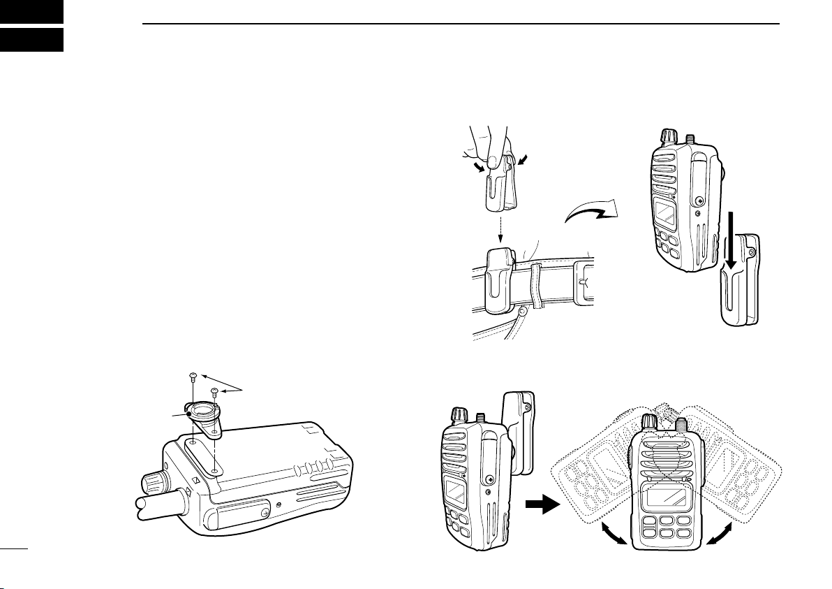
• The following accessories are authorized for use with this product. Use of
accessories other than those specified may result in RF exposure levels
exceeding the FCC and IC requirements for wireless RF exposure: Belt
Clip (MB-79), Swivel Belt Clip (MB-86), Rechargeable Li-ion Battery Pack
(BP-227), Alkaline Battery Case (BP-226) and Speaker-microphone (HM-
138).
CAUTION
To ensure that your expose to RF electromagnetic en-
ergy is within the FCC and IC allowable limits for occu-
pational use, always adhere to the following guidelines:
• DO NOT operate the radio without a proper antenna attached, as this may
damaged the radio and may also cause you to exceed FCC and IC RF ex-
posure limits. A proper antenna is the antenna supplied with this radio by
the manufacturer or antenna specifically authorized by the manufacturer
for use with this radio.
• DO NOT transmit for more than 50% of total radio use time (“50% duty
cycle”). Transmitting more than 50% of the time can cause FCC and
IC RF exposure compliance requirements to be exceeded. The radio is
transmitting when the transmit icon is displayed. You can cause the radio
to transmit by pressing the “PTT” switch.
• ALWAYS keep the antenna at least 2.5 cm (1 inch) away from the body
when transmitting and only use the Icom belt-clips which are listed on
page 35 when attaching the radio to your belt, etc., to ensure FCC and IC
RF exposure compliance requirements are not exceeded. To provide the
recipients of your transmission the best sound quality, hold the antenna at
least 5 cm (2 inches) from your mouth, and slightly off to one side.
The information listed above provides the user with the information needed
to make him or her aware of RF exposure, and what to do to assure that this
radio operates with the FCC and IC RF exposure limits of this radio.
Electromagnetic Interference/Compatibility
During transmissions, your Icom radio generates RF energy that can possibly
cause interference with other devices or systems. To avoid such interference,
turn off the radio in areas where signs are posted to do so. DO NOT operate
the transmitter in areas that are sensitive to electromagnetic radiation such as
hospitals, aircraft, and blasting sites.
Occupational/Controlled Use
The radio transmitter is used in situations in which persons are exposed as
consequence of their employment provided those persons are fully aware of
the potential for exposure and can exercise control over their exposure.
SAFETY TRAINING INFORMATION

RDANGER! NEVER short the terminals of the bat-
tery pack. Also, current may flow into metal objects such as
a key, so be careful when placing the battery packs (or the
transceiver) in bags, and so on. Simply carrying with or plac-
ing near metal objects such as a key, and so on, may cause
shorting. This may damage not only the battery pack, but also
the transceiver.
RDANGER! Use and charge only specified Icom bat-
tery packs with Icom transceivers or Icom chargers. Only
Icom battery packs are tested and approved for use with Icom
transceivers or charged with Icom chargers. Using third-party
or counterfeit battery packs or chargers may cause smoke,
fire, or cause the battery to burst.
RDANGER! NEVER operate the transceiver near
unshielded electrical blasting caps or in an explosive atmo-
sphere.
RWARNING! NEVER hold the transceiver so that
the antenna is closer than 2.5 cm (1 inch) from exposed parts
of the body, especially the face or eyes, while transmitting.
CAUTION: NEVER connect the transceiver to a power
source other than the products specified by Icom. Such a
connection will ruin the transceiver.
CAUTION: MAKE SURE the flexible antenna, bat-
tery pack and jack cover are securely attached to the trans-
ceiver, and that the antenna and battery pack are dry before
attachment. Exposing the inside of the transceiver to dust or
water will result in serious damage to the transceiver.
After exposure to water, clean the battery contacts thor-
oughly with fresh water and dry them completely to remove
any water or salt residue.
DO NOT place or leave the transceiver in direct sunlight
or in areas with temperatures below –20°C (–4°F) or above
+60°C (+140°F): Marine, below –30°C (–22°F) or above
+60°C (+140°F): LMR.
DO NOT use harsh solvents such as Benzine or alcohol
when cleaning, as they will damage the transceiver surfaces.
DO NOT push [PTT] when not actually intending to transmit.
DO NOT modify the transceiver. The transceiver warranty
does not cover any problems caused by unauthorized mod-
ification.
iv
PRECAUTIONS

v
KEEP the transceiver out of the reach of unauthorized per-
sons.
KEEP the transceiver at least 0.9 meters (3.0 ft) away from
your vessel’s magnetic navigation compass.
BE CAREFUL! The transceiver meets IPX7* require-
ments for waterproof protection. However, once the trans-
ceiver has been dropped, waterproof protection cannot be
guaranteed because of possible damage to the transceiver's
case or the waterproof seal.
* Only when the battery pack, flexible antenna, [SP MIC] jack cover
is attached.
MAKE SURE to turn OFF the transceiver before con-
necting or disconnecting the supplied or optional accessory.
PRECAUTIONS (Continued) FCC INFORMATION
• FOR CLASS A UNINTENTIONAL RADIATORS:
This equipment has been tested and found to comply with the
limits for a Class A digital device, pursuant to part 15 of the FCC
Rules. These limits are designed to provide reasonable protec-
tion against harmful interference when the equipment is oper-
ated in a commercial environment. This equipment generates,
uses, and can radiate radio frequency energy and, if not installed
and used in accordance with the instruction manual, may cause
harmful interference to radio communications. Operation of this
equipment in a residential area is likely to cause harmful interfer-
ence in which case the user will be required to correct the inter-
ference at his own expense.
CAUTION: Changes or modifications to this device, not ex-
pressly approved by Icom Inc., could void your authority to
operate this device under FCC regulations.
Icom is not responsible for the destruction or damage to the
Icom transceiver, if the malfunction is because of:
• Force majeure, including, but not limited to, fires, earth-
quakes, storms, floods, lightning, other natural disasters,
disturbances, riots, war, or radioactive contamination.
• The use of Icom transceivers with any equipment that is
not manufactured or approved by Icom.

vi
TABLE OF CONTENTS
IMPORTANT.......................................................................... i
EXPLICIT DEFINITIONS....................................................... i
FEATURES............................................................................ i
RECOMMENDATION ........................................................... ii
IN CASE OF EMERGENCY................................................. ii
SAFETY TRAINING INFORMATION................................... iii
PRECAUTIONS................................................................... iv
FCC INFORMATION ............................................................ v
1 OPERATING RULES.......................................................1
DPriorities.......................................................................1
DPrivacy .........................................................................1
DRadio licenses .............................................................1
2 SUPPLIED ACCESSORIES AND ATTACHMENTS....2–3
■Supplied accessories ...................................................2
■Attachments .................................................................2
DSwivel belt clip..........................................................2
DFlexible antenna.......................................................3
DHandstrap.................................................................3
3 PANEL DESCRIPTION................................................4–7
■Front, top and side panels............................................4
DBattery pack release button .....................................5
■Function display ...........................................................6
4 BASIC OPERATION..................................................8–12
■Selecting a Channel .....................................................8
DChannel 16...............................................................8
DChannel 9 (Call channel) .........................................8
DUSA, International and Canadian channels .............9
DWeather channels (Available for USA version only).......9
■Receiving and transmitting.........................................10
■Adjusting the squelch level.........................................11
■Automatic backlight ....................................................11
■Lock function ..............................................................11
■Setting the Call channel .............................................12
5 SCAN OPERATION.................................................13–14
■Scan types .................................................................13
■Setting Tag channels ..................................................14
■Starting a scan ...........................................................14
6 DUALWATCH and TRI-WATCH.....................................15
■About Dualwatch and Tri-watch..................................15
■Operation....................................................................15
7 LAND CHANNEL OPERATION ......................................16
■LAND Channel Group ................................................16
■Function display .........................................................16

vii
TABLE OF CONTENTS (Continued)
8 SET MODE ..............................................................17–21
■Set mode programming..............................................17
DSet mode operation................................................17
■Set mode items ..........................................................18
DBeep Tone function “bP”.........................................18
DWeather Alert function “AL” ....................................18
DPriority Scan function “Pr” .....................................18
DScan Resume timer “St”........................................18
DAuto Scan function “AS”........................................19
DDualwatch or Tri-watch function “dt” ......................19
DMonitor Key Action “Sq”..........................................19
DAutomatic Backlighting “bL” ...................................19
DLCD Contrast “LC”.................................................20
DAuto Power Save function “PS” .............................20
DSelf Check function “SC”.......................................20
DBattery Voltage indicator “bt”.................................21
9 BATTERY CHARGING ............................................22–27
■Caution.......................................................................22
DBattery caution.......................................................22
DCharging caution....................................................24
■Supplied battery charger............................................24
DCharging connections ............................................24
DFor your convenience.............................................25
■Optional battery chargers...........................................26
DAD-100 installation.................................................26
DRapid charging with the BC-119N+AD-100 ...........26
DRapid charging with the BC-121N+AD-100 ...........27
10 BATTERY CASE............................................................28
■BP-226 optional battery case.....................................28
11 SPEAKER-MICROPHONE............................................29
■HM-138 Description ...................................................29
■Attachments ...............................................................29
12 TROUBLESHOOTING...................................................30
13 VHF MARINE CHANNEL LIST .....................................31
14 SPECIFICATIONS .........................................................32
DGENERAL..................................................................32
DTRANSMITTER .........................................................32
DRECEIVER.................................................................32
15 QUICK REFERENCE ..............................................33–34
16 OPTIONS.......................................................................35
DBATTERY PACKS/CASE............................................35
DCHARGER .................................................................35
DDC CABLES...............................................................35
DOTHER OPTIONS .....................................................35

D Priorities
• Read all rules and regulations pertaining to priorities and
keep an up-to-date copy handy. Safety and distress calls
take priority over all others.
• You must monitor Channel 16 when you are not operating
on another channel.
• False or fraudulent distress calls are prohibited under law.
D Privacy
• Information overheard but not intended for you cannot law-
fully be used in any way.
• Indecent or profane language is prohibited.
D Radio licenses
(1) SHIP STATION LICENSE
When your craft is equipped with a VHF FM transceiver, you
must have a current radio station license before using the
transceiver. It is unlawful to operate a ship station which is
not licensed.
Inquire through your dealer or the appropriate government
agency for a Ship-Radiotelephone license. This license in-
cludes the call sign which is your craft’s identification for
radio purposes.
(2) OPERATOR’S LICENSE
A restricted Radiotelephone Operator Permit is the license
most often held by small vessel radio operators when a radio
is not required for safety purposes.
The Restricted Radiotelephone Operator Permit must be
posted near the transceiver or be kept with the operator. Only
a licensed radio operator may operate a transceiver.
However, non-licensed individuals may talk over a trans-
ceiver if a licensed operator starts, supervises, ends the call
and makes the necessary log entries.
A current copy of the applicable government rules and regu-
lations is only required to be on hand for vessels in which a
radio telephone is compulsory. However, even if you are not
required to have these on hand it is your responsibility to be
thoroughly acquainted with all pertinent rules and regulations.
NOTE: Even though the IC-M88 is capable of operation on
VHF marine channels 3, 21, 23, 61, 64, 81, 82 and 83, ac-
cording to FCC regulations these simplex channels cannot
be lawfully used by the general public in USA waters.
1
OPERATING RULES
1
2
3
4
5
6
7
8
9
10
11
12
13
14
15
16
1

■Supplied accessories
The following accessories are supplied: Qty.
• Swivel belt clip................................................................... 1
• Stopper for the swivel belt clip........................................... 1
• Screws for the swivel belt clip ........................................... 2
• Flexible antenna................................................................ 1
• Handstrap.......................................................................... 1
• Battery pack ...................................................................... 1
• Power adapter................................................................... 1
• Battery charger.................................................................. 1
■Attachments
DSwivel belt clip
To attach:
qAttach the stopper to the back of the transceiver.
Supplied screws
Stopper
wClip the belt clip to a part of your belt and insert the stop-
per to the belt clip.
eOnce the transceiver is locked in place, it will swivel 360
degrees.
2
2SUPPLIED ACCESSORIES AND ATTACHMENTS

To remove:
Turn the transceiver upside down, and then lift up to release
the transceiver from the belt clip.
CAUTION:
HOLD THE TRANSCEIVER TIGHTLY, WHEN ATTACH-
ING OR REMOVING THE TRANSCEIVER FROM THE
BELT CLIP.
If the transceiver is accidentally dropped and the swivel belt
clip’s stopper is scratched or damaged, the swivel belt clip
may not work properly.
DFlexible antenna
Connect the supplied flexible antenna
to the antenna connector.
CAUTION:
• NEVER carry the transceiver by
holding only the antenna.
•DO NOT connect the antenna
other than the supplied one.
•Transmitting without an antenna
will damage the transceiver.
DHandstrap
Pass the handstrap through
the loop on the back side of
the transceiver as illustrated
at right. This facilitates car-
rying.
3
2
SUPPLIED ACCESSORIES AND ATTACHMENTS
1
2
3
4
5
6
7
8
9
10
11
12
13
14
15
16

■Front, top and side panels
q
r
t
w
y
e
u
i
o
!0
qVOLUME CONTROL [VOL]
Push to turn ON the power and adjusts the audio level.
wANTENNA CONNECTOR (p. 3)
Connects the supplied antenna.
eSPEAKER-MICROPHONE CONNECTOR [SP MIC]
(p. 29)
Connects the optional speaker-microphone.
[SP MIC] jack cover
NOTE: KEEP the [SP
MIC] jack cover
attached to the transceiver when
the
speaker-microphone is not in use.
rSCAN KEY [SCN•DUAL] (pp. 14, 15)
• Push to start or stop the Normal or Priority scan.
• Hold down for 1 second to start Dualwatch or Tri-watch.
tTRANSMIT POWER/LOCK KEY [H/L•LOCK]
• Push to select the High, Mid or Low power level. (p. 10)
• Hold down for 1 second to turn the Lock function ON or
OFF. (p. 12)
yCHANNEL 16 KEY [16•9]
• Push to select Channel 16. (p. 8)
• Hold down for 1 second to select the Call channel. (p. 8)
• When the Call channel is selected, hold down for 3 sec-
onds to enter the Call channel entry mode. (p. 12)
4
3PANEL DESCRIPTION

uCHANNEL UP/DOWN KEYS [Y]/[Z]
• Push to select an operating channel. (p. 9)
• Push to select the Set mode item option. (p. 17)
• Push to check Tag channels, or change scanning direc-
tion during a scan. (p. 14)
• Hold down both keys for 1 second to set or clear the dis-
played channel as a Tag (scanned) channel.
• While holding down this key, turn ON the power to clear
all Tag channels in the selected channel group.
iCHANNEL/WEATHER CHANNEL KEY
[CH/WX•U/I/C/L]
• Push to toggle the regular channels and Weather chan-
nel group. (pp. 8, 9, 16)
• Hold down for 1 second to sequentially select one of 4
regular channels. (pp. 9, 16)
- USA, International, Canadian and Land channels are
selectable.
• Push to return to the mode before selecting the channel
when the Priority channel or the Call channel is selected.
oSQUELCH KEY [SQL] (p. 11)
• Push this key, then set the squelch level with [Y]/[Z].
• While holding down this key, you can manually open the
squelch to monitor the channel.
• While holding down this key, turn ON the power to enter
the Set mode.
!0 PTT SWITCH [PTT]
Hold down to transmit, release to receive.
DBattery pack release button
To remove the battery pack:
Push the battery release button in the direction of the arrow
(q) as shown below. The battery pack can then be removed.
To attach the battery pack:
Slide the battery pack on the back of the transceiver in the di-
rection of the arrow (w), then lock it with the battery release
button.
• Slide the battery pack until the battery release button makes
a ‘click’ sound.
w
q
Battery pack
Batter
y release
button
CAUTION: When pushing the battery release button, slide
the battery pack slightly in the direction of the arrow (w) to
ease release. This will prevent possible injuring your fin-
gers or nails.
NOTE: Keep the battery pack terminals clean. It’s a good
idea to occasionally clean them.
NEVER remove or attach the battery pack when the trans-
ceiver is wet or soiled. This may result water or dust get-
ting into the transceiver/battery pack and may result in
damaging the transceiver. 5
3
PANEL DESCRIPTION
1
2
3
4
5
6
7
8
9
10
11
12
13
14
15
16

■Function display
qw ertyu
i
o
!0
!1
!2!3
!4
!5
!6
q TRANSMIT ICON (p. 10)
Displayed while transmitting.
w BUSY ICON (p. 10)
• Displayed when receiving a signal or when the squelch
opens.
• Blinks while monitoring.
e TAG CHANNEL ICON (p. 14)
Displayed when a Tag channel is selected.
r SCAN ICON (p. 14)
Blinks while scanning.
t LOCK ICON (p. 12)
Displayed while the lock function is activated.
y NARROW ICON (p. 16)
Displayed when narrow channel spacing is selected.
(Only LAND channel group)
u BATTERY ICON
Displays remaining battery capacity.
Indication
Full Mid Charging
required Exhausted
Battery status
blinks when the battery is over charged.
6
3PANEL DESCRIPTION

i
WEATHER CHANNEL/WEATHER ALERT
ICON
S
• “WX” is displayed when the Weather channel group is
selected. (p. 9)
• “ALT” is displayed while the Weather Alert function is ac-
tivated.
o BELL ICON
Blinks when an Alert tone is received.
!0 DUALWATCH/TRI-WATCH ICONS (p. 15)
• “DUAL” is displayed during Dualwatch.
• “TRI” is displayed during Tri-watch.
!1 DUPLEX ICON
Displayed when a Duplex channel is selected.
!2 SUB CHANNEL READOUT
• Displays Channel 16 during Priority scan, Dualwatch or
Tri-watch. (p. 15)
• In the Set mode, displays the selected Set mode item.
!3 CHANNEL NUMBER READOUT
• Displays the selected operating channel number.
• In the Set mode, displays the selected condition.
!4 CALL CHANNEL ICON (p. 8)
Displayed when the Call channel is selected.
!5 CHANNEL GROUP ICON (pp. 9, 16)
• “U” is displayed when the USA channel group is se-
lected.
• “I” is displayed when the International channel group is
selected.
• “C” is displayed when the Canadian channel group is
selected.
• “ ” is displayed when the LAND channel group is se-
lected.
!6 TRANSMIT POWER ICON (p. 10)
• “LOW” is displayed when Low power is selected.
• “MID” is displayed when Mid power is selected.
• No indication is displayed when High power is selected.
7
3
PANEL DESCRIPTION
1
2
3
4
5
6
7
8
9
10
11
12
13
14
15
16

■Selecting a Channel
IMPORTANT: Prior to using the transceiver for the first
time, the battery pack must be fully charged for optimum
life and operation. To avoid damage to the transceiver,
turn OFF the power while charging.
DChannel 16
Channel 16 (Distress channel) is used to establish the initial
contact with another station, and for emergency communi-
cations. Channel 16 is automatically monitored during both
Dualwatch and Tri-watch. While standing by, you must moni-
tor Channel 16.
qPush [16•9] to select Channel 16.
wPush [CH/WX•U/I/C/L] to return to the mode before select-
ing Channel 16, or push [Y] or [Z] to select the operat-
ing channel.
Push
9
DChannel 9 (Call channel)
Channel 9 is the leisure-use Call channel. Each regular chan-
nel group has separate Call channels. In addition, each Call
channel is monitored during Tri-watch. The Call channels can
be set (p. 12) and are used to store your most often-used
channels in each channel group for quick recall.
qHold down [16•9] for 1 second to select the Call channel in
the selected channel group.
• “CALL” and the Call channel number appear.
• Each channel group may have its own Call channel after setting
it. See “Setting the Call channel” on page 12 for details.
wPush [CH/WX•U/I/C/L] to return to the mode before select-
ing Channel 9 (Call channel), or push [Y] or [Z] to select
the operating channel.
Hold down
for 1 second
9
8
4BASIC OPERATION

DUSA, International and Canadian channels
There are 57 USA, 57 International, and 61 Canadian chan-
nels. Choose the appropriate channel group for your operat-
ing area, and then select a desired channel.
qPush [CH/WX•U/I/C/L] to select a regular channel.
• If a Weather channel appears, push [CH/WX•U/I/C/L] again.
wPush [Y] or [Z] to select a channel.
• “DUP” appears for duplex channels.
eTo change the channel group, hold down [CH/WX•U/I/C/L]
for 1 second.
• USA, International and Canadian channels can be sequentially
selected. Depending on the setting, LAND channel can be se-
lected. See “LAND CHANNEL OPERATION” on page 16 for de-
tails.
Hold down
for 1 second
USA channels
International channels Canadian channels
U/I/C/L
U/I/C/L
U/I/C/L
DWeather channels (Available for USA version only)
There are 10 Weather channels. They are used for monitoring
Weather channels from the NOAA (National Oceanographic
and Atmospheric Administration) broadcasts.
qPush [CH/WX•U/I/C/L] to select the Weather channel
group.
wPush [Y] or [Z] to select a Weather channel.
ePush [CH/WX•U/I/C/L] to return to the mode before select-
ing the Weather channel group.
Push
U/I/C/L
For your convenience: The IC-M88 can detect a Weather
alert tone on the selected Weather channel while receiving
on another channel or during a scan. See the “Set mode
items” on page 18 for details.
9
4
BASIC OPERATION
1
2
3
4
5
6
7
8
9
10
11
12
13
14
15
16

■Receiving and transmitting
CAUTION: Transmitting without an antenna will damage
the transceiver.
q Rotate [VOL] clockwise to turn ON the power.
w Use the squelch function to mute any audio noise if neces-
sary. After holding down [SQL] for 1 second, the squelch
function is cut off until [SQL] is released. (default)
e Hold down [SQL] for 1 second (see “Set mode” on page
19), and rotate volume to set the volume level.
r Push [Y] or [Z] to select a channel.
- While receiving a signal, “ ” appears and audio is heard from
the speaker.
- Further adjustment of [VOL] may be necessary at this point.
t Push [H/L•LOCK] to select the output power if necessary.
- “LOW” is displayed when low power is selected, “MID” is dis-
played when middle power is selected, No indication is dis-
played when high power is selected.
- Choose Low power to conserve the battery power, choose High
power for long range communications.
- Some channels are restricted to Low power only.
y Hold down [PTT] to transmit, then speak into the micro-
phone.
- “TX” appears.
- You cannot transmit on Channel 70.
u Release [PTT] to receive.
IMPORTANT: To maximize the readability of your trans-
mitted signal, pause a few second after holding down
[PTT], hold the microphone 5 to 10 cm (2 to 4 inches) from
your mouth and speak at your normal voice level.
NOTE: The transceiver has a Power Save function to con-
serve the battery power and it cannot be turned OFF. The
Power Save function automatically activates when no sig-
nal is received for 5 seconds.
For USA version: To prevent accidental prolonged trans-
mission, the IC-M88 has a time-out timer function. This
timer cuts the transmission OFF after 5 minutes of contin-
uous transmission.
r Set the
channel
wOpen the
squelch
qPower ON
eSet volume
t Set the
output power
yHold down
to transmit
uRelease to
receive
10
4BASIC OPERATION

■Adjusting the squelch level
The IC-M88 has a squelch circuitry. In order to receive the sig-
nals properly, as well as for the efficient scan, the squelch must
be adjusted to the proper level.
qPush [SQL], then adjust the squelch level with [Y]/[Z].
- “SL” indicator is displayed.
- There are 11 squelch levels. OP is completely open, 10 is the
tightest squelch level.
- When no key is pushed for 5 seconds, the transceiver returns to
the normal condition.
wPush [SQL] again to return to the normal condition.
■Automatic backlight
This function is convenient for nighttime operation. The auto-
matic backlight can be activated in the Set mode. (p. 19)
➥Push any key except [PTT] to turn ON the backlight.
• The backlight is automatically turned OFF after 5 seconds of in-
activity.
■Lock function
This function electronically locks all keys (except for [PTT],
[SQL] and [H/L•LOCK]) to prevent accidental channel
changes and function access.
• Hold down [H/L•LOCK] for 1 second to turn the lock function ON
and OFF.
Displayed when the
Lock function is ON.
11
4
BASIC OPERATION
1
2
3
4
5
6
7
8
9
10
11
12
13
14
15
16

■Setting the Call channel
The Call channel key is used to select Channel 9 by default,
however, you can set your most often-used channels in each
channel group for quick recall.
qHold down [CH/WX•U/I/C/L] for
1 second several times to select
the desired channel group (USA,
INT, CAN) to be used.
wHold down [16•9] for 1 second to
select the Call channel.
• “CALL” and Call channel number
appear.
eHold down [16•9] again for 3 sec-
onds (until a long beep changes
to 2 short beeps) to enter Call
channel programming condition.
• Call channel number to be pro-
grammed flashes.
rPush [Y] or [Z] to select the de-
sired channel.
tPush [16•9] to program the dis-
played channel as the Call chan-
nel.
• The Call channel number stops
blinking.
12
4BASIC OPERATION
Other manuals for IC-M88
6
Table of contents
Other Icom Transceiver manuals

Icom
Icom IC-T7H User manual

Icom
Icom IC-F3162T User manual

Icom
Icom IC-F3210D Series User manual

Icom
Icom iM304 User manual

Icom
Icom IC-F3021T User manual

Icom
Icom IC-F3400DP Series User manual

Icom
Icom IC-V86 Setup guide

Icom
Icom IC-F7510 Series User manual

Icom
Icom IC-281H User manual

Icom
Icom IC-H16 User manual