Icom IC-F3210D Series User manual

INSTRUCTION MANUAL
This device complies with Part 15 of the FCC Rules.
Operation is subject to the condition that this device
does not cause harmful interference.
The photo shows the
VHF transceiver.
UHF DIGITAL TRANSCEIVERS
iF4210D
Series
VHF DIGITAL TRANSCEIVERS
iF3210D
Series

i
FOREWORD
READ ALL INSTRUCTIONS carefully and completely before
using the transceiver.
SAVE THIS INSTRUCTION MANUAL— This instruction
manual contains important operating instructions for the IC-F3210D
VHF DIGITAL TRANSCEIVER and the IC-F4210D UHF DIGITAL
TRANSCEIVER.
See the operating guide for details of IDAS (ICOM Digital Ad-
vanced System) system operations. Ask your dealer for details.
EXPLICIT DEFINITIONS
WORD DEFINITION
RDANGER! Personal death, serious injury or an explosion
may occur.
RWARNING! Personal injury, fire hazard or electric shock
may occur.
CAUTION Equipment damage may occur.
NOTE If disregarded, inconvenience only. No risk of
personal injury, fire or electric shock.
Icom, Icom Inc. and the Icom logo are registered trademarks of Icom Incorpo-
rated (Japan) in Japan, the United States, the United Kingdom, Germany, France,
Spain, Russia and/or other countries.

ii
FCC INFORMATION
• FOR CLASS A UNINTENTIONAL RADIATORS:
This equipment has been tested and found to comply with the limits
for a Class A digital device, pursuant to part 15 of the FCC Rules.
These limits are designed to provide reasonable protection against
harmful interference when the equipment is operated in a commer-
cial environment. This equipment generates, uses, and can radiate
radio frequency energy and, if not installed and used in accordance
with the instruction manual, may cause harmful interference to ra-
dio communications.
Operation of this equipment in a residential area is likely to cause
harmful interference in which case the user will be required to cor-
rect the interference at his own expense.
CAUTION: Changes or modifications to this device, not expressly
approved by Icom Inc., could void your authority to operate this
transceiver under FCC regulations.

iii
PRECAUTIONS
RDANGER! NEVER short the terminals of the battery pack.
RDANGER! Use and charge only specified Icom battery packs
with Icom radios or Icom chargers. Only Icom battery packs are
tested and approved for use with Icom radios or charged with Icom
chargers. Using third-party or counterfeit battery packs or chargers
may cause smoke, fire, or cause the battery to burst.
RWARNING! NEVER hold the transceiver so that the antenna
is very close to, or touching exposed parts of the body, especially
the face or eyes, while transmitting. The transceiver will perform
best if the microphone is 5 to 10 cm (2 to 4 inches) away from the
lips and the transceiver is vertical.
RWARNING! NEVER operate the transceiver with a headset
or other audio accessories at high volume levels. Hearing experts
advise against continuous high volume operation. If you experience
a ringing in your ears, reduce the volume level or discontinue use.
RWARNING! NEVER operate the transceiver while driving a
vehicle. Safe driving requires your full attention—anything less may
result in an accident.
CAUTION: MAKE SURE the flexible antenna and battery pack
are securely attached to the transceiver, and that the antenna and
battery pack are dry before attachment. Exposing the inside of the
transceiver to water will result in serious damage to the transceiver.
DO NOT operate the transceiver near unshielded electrical blast-
ing caps or in an explosive atmosphere.
DO NOT push [PTT] when not actually intending to transmit.
DO NOT use or place the transceiver in direct sunlight or in areas
with temperatures below –30°C (+22°F) or above +60°C (+140°F).

iv
PRECAUTIONS
DO NOT modify the transceiver. The transceiver warranty does
not cover any problems caused by unauthorized modification.
DO NOT use harsh solvents such as benzine or alcohol when
cleaning, as they will damage the transceiver surfaces.
BE CAREFUL! The transceiver will become hot when operating
it continuously for long periods of time.
KEEP the transceiver away from heavy rain, and never immerse
it in the water. The transceiver meets IP54* requirements for dust-
protection and splash resistance. However, once the transceiver
has been dropped, dust-protection and splash resistance cannot
be guaranteed because of possible damage to the transceiver’s
case or the waterproof seal.
* Only when the battery pack/case and jack cover are attached.
Even when the transceiver power is OFF, a slight current still flows
in the circuits. Remove the battery pack or batteries from the trans-
ceiver when not using it for a long time. Otherwise, the installed
battery pack or batteries will become exhausted, and will need to
be recharged or replaced.
MAKE SURE to turn the transceiver power OFF before connect-
ing the supplied/optional equipment.

v
VOICE CODING TECHNOLOGY
The AMBE+2™ voice coding Technology embodied in this product
is protected by intellectual property rights including patent rights,
copyrights and trade secrets of Digital Voice Systems, Inc.This voice
coding Technology is licensed solely for use within this Communica-
tions Equipment. The user of this Technology is explicitly prohibited
from attempting to extract, remove, decompile, reverse engineer, or
disassemble the Object Code, or in any other way convert the Ob-
ject Code into a human-readable form. U.S. Patent Nos.
#5,870,405, #5,826,222, #5,754,974, #5,701,390, #5,715,365,
#5,649,050, #5,630,011, #5,581,656, #5,517,511, #5,491,772,
#5,247,579, #5,226,084 and #5,195,166.
SUPPLIED ACCESSORIES
The following accessories are supplied with the transceiver.
Flexible antenna
(This illustration is for the VHF type.)
Battery pack*
Belt clip* Jack cover
(with screws)
Battery charger*AC adapter*
*Not supplied, or
the shape is differ-
ent, depending on
the version.

vi
TABLE OF CONTENTS
FOREWORD .................................................................................. i
EXPLICIT DEFINITIONS................................................................ i
FCC INFORMATION ......................................................................ii
PRECAUTIONS.............................................................................iii
VOICE CODING TECHNOLOGY .................................................. v
SUPPLIED ACCESSORIES.......................................................... v
TABLE OF CONTENTS.................................................................vi
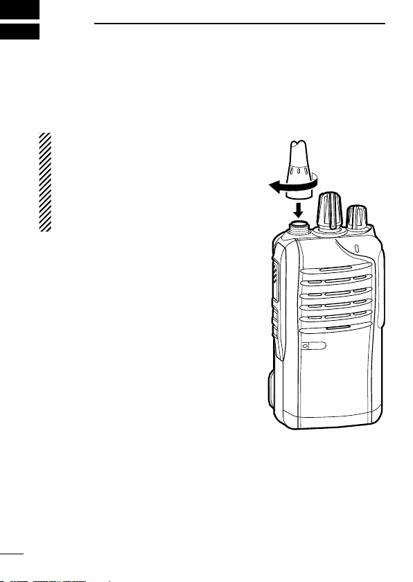
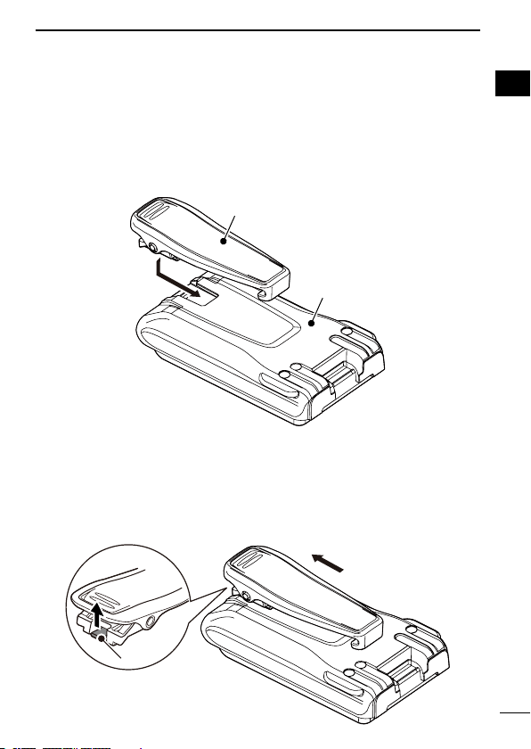
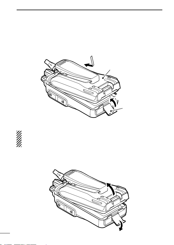
1 ACCESSORIES.................................................................... 1–4
Accessory attachments
■........................................................ 1
2 PANEL DESCRIPTION ...................................................... 5–11
Front, top and side panels
■.................................................... 5
LED indicator
■........................................................................ 7
Programmable function keys
■................................................ 9
3 BASIC OPERATION......................................................... 12–20
Turning power ON
■............................................................... 12
Channel selection
■............................................................... 13
Receiving and transmitting
■................................................. 14
Setting the microphone gain
■............................................... 16
Setting the squelch level
■..................................................... 17
Setting the Beep level
■......................................................... 18
Setting the Ringer level
■....................................................... 19
Output power level selection
■............................................... 20
Priority A channel selection
■................................................ 20
4 BATTERY CHARGING..................................................... 21–31
Caution (for the BP-264
■ni-m h b at t e r y ) ............................. 21
Caution (for the BP-265
■Li-ion b at t e r y ) ............................. 23
Battery chargers
■................................................................. 26
5 BATTERY CASE .................................................................... 32
Optional battery case (BP-263)
■.......................................... 32
6 OPTIONS.......................................................................... 33–38
VOX function
■....................................................................... 36
7 SAFETY TRAINING INFORMATION ............................... 39–40

Accessory attachments■
Flexible antennaD
Connect the flexible antenna to the antenna connector.
CAUTION:
• NEVER carry the transceiver by
holding only the antenna.
• DO NOT connect the antenna other
than listed on page 34.
• Transmitting without an antenna will
damage the transceiver.
1
1ACCESSORIES

2
1
ACCESSORIES
1
2
3
4
5
6
7
8
9
10
11
12
13
14
15
16
17
18
19
20
Belt clipD
To attach the belt clip:
Slide the belt clip in the direction of the arrow until the belt clip➥
locks in place, and makes a ‘click’ sound.
Battery pack
Belt clip
To detach the belt clip:
Remove the battery pack from the transceiver, if it is attached.q
(p. 3)
Lift the tab up (wq), and slide the belt clip in the direction of the
arrow (w).
w
q
Ta b

3
1ACCESSORIES
Battery pack or caseD
To attach the battery pack or case:
Fit the battery pack/case in the direction of the arrow, then closeq
it.
Hook the latch until it makes a ‘click’ sound.w
q
Latch
w
Battery pack/case
To remove the battery pack/case:
Be careful! The latch is tightly locked, so use caution when re-
leasing it. DO NOT use your finger nail. Use the edge of a coin
or screwdriver tip to carefully release it
.
q Unhook the latch.
w Lift up the
battery pack/case
in the direction of the arrow.
q
w

4
1
ACCESSORIES
1
2
3
4
5
6
7
8
9
10
11
12
13
14
15
16
17
18
19
20
NEVER remove or attach the battery pack/case when the trans-
ceiver is wet or soiled. This may result in water or dust getting
into the transceiver, battery pack/case, and may result in them
being damaged.
NOTE: Keep the battery terminals clean. It’s a good idea to oc-
casionally clean them.
Jack coverD
Attach the jack cover when optional equipment is not used.
To attach the jack cover:
Attach the jack cover to theq
[SP MIC] jack.
Tighten the screws.w
To detach the jack cover:
qRemove the screws with a
phillips screwdriver.
wDetach the jack cover to con-
nect the optional equipment.
w
w
w
q
q
q

5
2PANEL DESCRIPTION
Front, top and side panels■
Microphone
Speaker
r
w
e
q
y
u
i
tLOWER KEY
UPPER KEY
PTT SWITCH
ANTENNA
CONNECTOR
ROTARY
SELECTOR
LED INDICATOR
VOLUME
CONTROL
SPEAKER-
MICROPHONE
JACK
qROTARY SELECTOR
Rotate to select the preprogrammed memory channels or TX
Status list number*, depending on the preprogrammed.
*Digital operation only
wVOLUME CONTROL [VOL]
Rotate to turn the power ON or OFF, and adjust the audio level.

6
2
PANEL DESCRIPTION
eLED INDICATOR (p. 7)
Lights red* while transmitting.➥
* When the attached battery type is set to “Alkaline Dry,” the LED
indicator lights orange.
Lights green while receiving a signal, or when the squelch➥
is open.
Lights or blinks orange while receiving a status call, a SDM➥
(Short Data Message) or a Call Alert call.
r SPEAKER-MICROPHONE JACK [SP MIC]
Connect the optional speaker-microphone or VOX adapter ca-
ble.
t LOWER KEY [Lower]
y UPPER KEY [Upper]
A desired function can be assigned by your dealer. (p. 9)
u PTT SWITCH [PTT]
Hold down to transmit; release to receive.
iANTENNA CONNECTOR
Connect the antenna.
1
2
3
4
5
6
7
8
9
10
11
12
13
14
15
16
17
18
19
20
Jack cover
NOTE: Attach the jack cover
when optional equipment is
not used. (p. 4)

7
2PANEL DESCRIPTION
LED indicator■
The LED indicator indicates the status of various
parameters of the transceiver as follows;
(Reference: R=Red, G=Green, O=Orange)
• TX: Lights while transmitting a signal.
• RX: Lights while receiving a signal.
• Scan: Blinks when the scan is activated.
• Low Battery 1: You should charge the battery. (blinks slowly)
• Low Battery 2: You must charge the battery. (blinks fast)
• TX low Battery 2: Very Low Battery was detected during TX mode.
• Channel Error: A non-programmed channel is selected.
* When the attached battery type is set to “Alkaline Dry,” the LED indica-
tor lights (or blinks) orange.
• TX low Battery 1: Low Battery was detected during TX mode.
R*
G
G G
G G
G G G G
R* R*
R* R* R* R*
R O R O R O R O R O R O R O R O
• CH Access: Blinks while accessing a channel to make a call.
• Audible: Blinks slowly when a mute is released.
O O O
O O O
O
O

8
2
PANEL DESCRIPTION
1
2
3
4
5
6
7
8
9
10
11
12
13
14
15
16
17
18
19
20
• Call LED (ON): Turns ON while receiving a status call, a SDM
(Short Data Message) or a Call Alert call, depend-
ing on the preprogramming.
• Call LED (Blink): Blinks while receiving a status call, a SDM (Short
Data Message) or a Call Alert call, depending on
the preprogramming.
• Success: Blinks slowly when your call is successful.
• Failure: Blinks slowly when your call fails, or it is refused.
O G
O R
• Power ON: Blinks at transceiver startup.
R O GRO G
O
O O
• TX inhibit: While in the TX inhibit mode and the TOT or Lockout
function is activated.
R O O O
• Emergency/Siren: Blinks when an Emergency call is received or a
Siren is activated.
G O R G O R G O R G O R

9
2PANEL DESCRIPTION
Programmable function keys■
The following functions can be assigned to the [Upper] and [Lower]
programmable function keys.
Consult your Icom dealer or system operator for details concerning
your transceiver’s programming.
NOTE: The function keys for the digital mode are described in
the operating guide.
SCAN START/STOP
Push to start and cancel the scanning operation.
• When the scan started with the Power ON Scan or Auto Scan func-
tion, push to pause the scanning operation. The paused scan re-
sumes after the specified time period has passed.
PRIORITY A CHANNEL, PRIORITY B CHANNEL
Push to select the Priority A or Priority B channel.
PRIORITY A CHANNEL (REWRITE),
PRIORITY B CHANNEL (REWRITE)
Push to select the Priority A or Priority B channel.➥
Hold down [Prio A (Rewrite)] or [Prio B (Rewrite)] for 1 second to➥
assign the operating channel to Priority A or Priority B channel,
respectively.

10
2
PANEL DESCRIPTION
1
2
3
4
5
6
7
8
9
10
11
12
13
14
15
16
17
18
19
20
MEMORY CHANNELS 1, 2, 3, 4
Push to directly select memory channel 1, 2, 3 or 4, if programmed.
Consult your dealer for details.
MONITOR
Push to turn the CTCSS (DTCS) squelch Mute ON or OFF.
LOCK
Hold down to electronically lock all programmable keys except
[Moni], [Lock], [Emergency]*, [Surveillance], [Siren] and [Lone
Worker]*.
* For digital operation. See the operating guide for details.
HIGH/LOW (p. 20)
Push to select the transmit output power level temporarily or per-
manently, depending on the presetting.
• Ask your dealer for the output power level for each selection.
TALK AROUND
Push to turn the Talk Around function OFF.➥
Hold down to turn the Talk Around function ON.➥
• The Talk Around function equalizes the transmit frequency to the
receive frequency for transceiver-to-transceiver communication.
WIDE/NARROW
Push to toggle the IF bandwidth between wide and narrow.
• When the wide bandwidth is selected, 3 beeps sound.
• When the narrow bandwidth is selected, 1 beep sounds.

11
2PANEL DESCRIPTION
Programmable function keys (Continued)■
SURVEILLANCE
Push to turn OFF the Surveillance function.➥
Hold down to turn ON the Surveillance function.➥
• When this function is turned ON and a signal is received, the beep
is not heard and the LED does not light even if a key is pushed.
SIREN
Hold down for 1 second to emit a siren sound.
This function can be used for situations other than an emergency
alert, such as a security alarm for example.
• The siren can only be stopped by turning OFF the transceiver power.
ANNOUNCE
Push to turn the Channel Announce function ON or OFF.
• When this function is turned ON, the transceiver announces the posi-
tion of [ROTARY SELECTOR] between 1 and 16 when rotating [RO-
TARY SELECTOR] to a desired scale.
RESET
Push to return to the normal operating mode.➥
While in the audible mode, push to return to the inaudible➥
mode.
NOTE: See the operating guide for the [Reset] key operations in
the digital mode.

12
3
BASIC OPERATION
1
2
3
4
5
6
7
8
9
10
11
12
13
14
15
16
17
18
19
20
Turning power ON■
Prior to using the transceiver for the first
time, the battery pack must be fully charged
for optimum life and operation. (p. 21)
Rotate [VOL] to turn power ON.➥
Battery type selectionD
The battery type must be selected according to the battery pack or
case when it is changed, but only the first time it is used.
Check the battery type before you begin the selection procedure.
One to three beeps sound in sequence, so you must repeat the
steps until the number of beeps matches your battery type.
For example, if your battery type is a Li-ion battery pack, you must
repeat the procedure until one beep is heard.
Rotate [VOL] to turn OFF the trans-q
ceiver’s power.
Setw
[ROTARY SELECTOR] to any
channel other than Channel 16.
While holding down [PTT], rotatee
[VOL] to turn ON the power.
• You should hold [PTT] until the bat-
tery type confirmation beeps sound.
(It takes approximately 5 seconds;
while holding down [PTT], the count
down beeps sound. After that, the confirmation beeps sound.)
• One beep sounds when the Li-ion battery is selected.
• Two beeps sound when the Alkaline Dry battery is selected.
• Three beeps sound when the Ni-MH battery is selected.
After the beep sounds, release [PTT].r
Repeat stepst w to runtil you select the attached battery type.
NOTE: This operation may not be available, depending on the
presetting. Ask your dealer for details.
[VOL]
[VOL]
[PTT]
[ROTARY SELECTOR]

Channel selection■
There are several ways to select channels, and they may differ,
depending on your system set up.
To select a desired operating channel, do one of the following.
• Rotate [ROTARY SELECTOR].
• Push one of memory channel keys, [MR-CH 1] to [MR-CH 4].
• Push one of these keys, [Prio A], [Prio B], [Prio A (Rewrite)] and
[Prio B (Rewrite)].
AUTOMATIC SCAN TYPE:
Channel setting is not necessary for this type. When turning ON the
power, the transceiver automatically starts scanning.
Scanning stops when a signal is detected.
13
3BASIC OPERATION
Other manuals for IC-F3210D Series
2
This manual suits for next models
3
Table of contents
Other Icom Transceiver manuals