IDW G-Series User manual
NSF/ANSI7
SA44689
Models:
GS-2.5-N234B
GS-2.5-W234B
GS-2.5-B234B
GS-2.5-P234B
GS-2.5-LN234B
GS-2.5-LW234B
GS-2.5-LB234B
GS-2.5-LP234B
GS-2.5-0234B
GS-2.5-L0234B
GS-2.5-2234B
GS-2.5-2W234B
GS-2.5-2B234B
GS-2.5-2P234B
GS-2.5-L2W234B
GS-2.5-L2B234B
GS-2.5-L2P234B
GS-2.5-A234B
GS-2.5-LA234B
GS-3-N234B
GS-3-W234B
GS-3-B234B
GS-3-P234B
GS-3-0234B
GS-3-2234B
GS-3-A234B
GS-3-2W234B
GS-3-2B234B
GS-3-2P234B
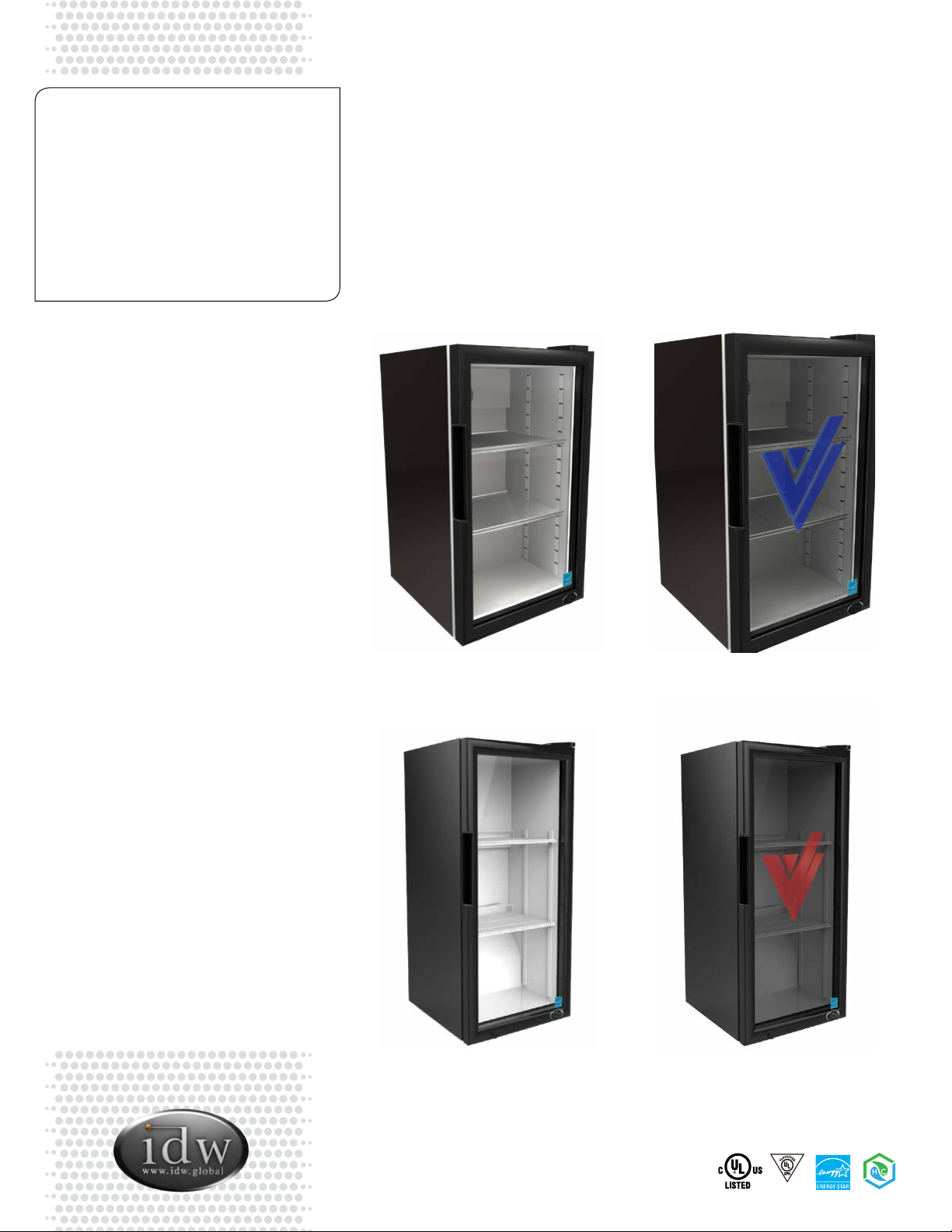
G-Series Cooler
Instruction Manual
G2.5
GS2.5
G3
GS3
G-2.5
G-3
GS-2.5
GS-3
For Future Reference
• This easy-to-use manual will guide you in getting the best use of your cooler.
• Remember to record the model number and the serial number. This information can be
found on the inside of your cooler.
• Keep your receipt with this manual for future warranty service.
Model #:
Serial #:
Date of Purchase:
Table of Contents
Parts & Identication (GS-2.5)...................... 4
Parts & Identication (G3/GS3) .................... 5
Safety Instructions & Precautions.................. 6
Installation........................................... 6
Electric Connection................................ 6
Start .................................................. 6
Maintenance .......................................... 7
Cleaning............................................. 7
Power Failure ....................................... 7
Moving the Cooler................................. 7
Drip Pan ............................................. 7
Leveling................................................ 7
Shelving Installation ................................. 8
Troubleshooting...................................... 9
Specications ........................................10
Flammable Refrigerant Warnings ................11
Switch Function......................................11
Circuit Diagrams (GS2.5) ..................... 12, 13
Circuit Diagrams (G3/GS3) ................... 14, 15
Models:
GS-2.5-N234B
GS-2.5-W234B
GS-2.5-B234B
GS-2.5-P234B
GS-2.5-LN234B
GS-2.5-LW234B
GS-2.5-LB234B
GS-2.5-LP234B
GS-2.5-0234B
GS-2.5-L0234B
GS-2.5-2234B
GS-2.5-2W234B
GS-2.5-2B234B
GS-2.5-2P234B
GS-2.5-L2W234B
GS-2.5-L2B234B
GS-2.5-L2P234B
GS-2.5-A234B
GS-2.5-LA234B
GS-3-N234B
GS-3-W234B
GS-3-B234B
GS-3-P234B
GS-3-0234B
GS-3-2234B
GS-3-A234B
GS-3-2W234B
GS-3-2B234B
GS-3-2P234B
G-Series Cooler
Instruction Manual
G-2.5
GS-2.5
G-3
GS-3
G-2.5/GS-2.5 G-3/G-S3
3Innovative DisplayWorks, Inc.
<< I found a manual for
G3/GS3, so that’s where I
got this list.
I didn’t nd a G2.5 manual
so I don’t have a list of
G2.5 models this manual
will cover.
Innovative DisplayWorks
offi ce 909.447.8254 • fax 909.305.8756 • toll free 877.307.2665 • www.idw.global
Last Revised: September 25, 2019 12:26 PM
GS-2.5
1. Cooler Cabinet
2. Evaporator
3. Circle Pipe
4. Evaporator Fan
5. Evaporator Safeguard
6. Evaporator Fan Cover
7. Rear Grill
8. Door Gasket
9. Glass Door
10. Top Hinge
11. Hinge Cover
12. LED (2)
13. Bottom Hinge
14. Bottom Hinge Washer
15. Lock
16. Key (2)
17. Large Shelf (2)
18. Shelf Strip (4)
19. Shelf Clip (8)
20. Lockpin
21. Magnetic Switch
22. Magentic Sensor
23. Condenser Support (4)
24. Thermostat
25. Transformer
26. Transformer Box
27. Leveling Leg (4)
28. Compressor Base
29. Compressor
30. Drip Pan
31. Thermostat Box
32. Thermostat Box Cover
33. Thermostat Label
34. Door Light Switch (2)
35. Filter Drier
36. Condenser Fan
37. Condenser Fan Cover
38. Fan Cover
39. Power Cord
40. Condenser
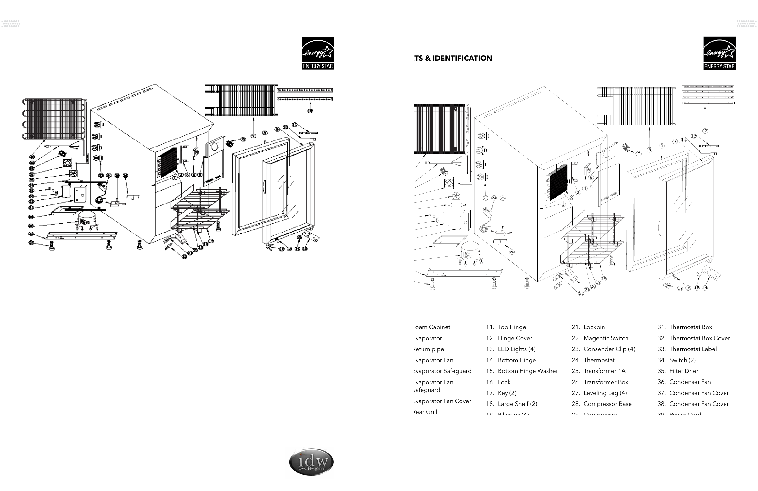
PARTS & IDENTIFICATION
Innovative DisplayWorks
offi ce 909.447.8254 • fax 909.305.8756 • toll free 877.307.2665 • www.idw.global
Last Revised: May 30, 2018 11:15 AM
G-3/GS-3
1. Foam Cabinet
2. Evaporator
3. Return pipe
4. Evaporator Fan
5. Evaporator Safeguard
6. Evaporator Fan
Safeguard
7. Evaporator Fan Cover
8. Rear Grill
9. Door Gasket
10. Glass Door
11. Top Hinge
12. Hinge Cover
13. LED Lights (4)
14. Bottom Hinge
15. Bottom Hinge Washer
16. Lock
17. Key (2)
18. Large Shelf (2)
19. Pilasters (4)
20. Shelf Clips (8)
21. Lockpin
22. Magentic Switch
23. Consender Clip (4)
24. Thermostat
25. Transformer 1A
26. Transformer Box
27. Leveling Leg (4)
28. Compressor Base
29. Compressor
30. Drip Pan
31. Thermostat Box
32. Thermostat Box Cover
33. Thermostat Label
34. Switch (2)
35. Filter Drier
36. Condenser Fan
37. Condenser Fan Cover
38. Condenser Fan Cover
39. Power Cord
40. Condenser
PARTS & IDENTIFICATION
GS2.5 G3-GS3
Instruction Manual G-2.5/GS-2.5 G-3/G-S3
4 5Innovative DisplayWorks, Inc.
GS2.5 (r600a, ES4) Parts List
Not sure of voltage. It seemed like I had to
choose the ES4, or 110V.
G3-GS3 (r600a, 110V) Parts List
No ES logo
I didn’t nd a G2.5 (r600a, ES4)
Parts List in the r600a “Parts List
Specs” folder.
1. To reduce the risk of re, electric shocks, or injury
when using your cooler, please note the following
basic precautions:
2. Never clean appliance parts with fl ammable fl uids.
3. Do not store or use gasoline or any other fl ammable
vapors and liquids in the vicinity of this or any other
appliance. The fumes can cause a re or explosion.
4. As with all electrical appliances, please consult a
licensed repair technician for any repairs.
5. Do not block the ventilation holes located on the top
of the cabinet.
Installation
• Keep cooler in an upright position for 1-hour prior to
use. This is essential for proper operation. If the cooler
is transported in the horizontal position, the cooler
must be returned to the upright position and not
plugged in for 1 hour.
• Remove all the packing material before using your
cooler.
• Clean the interior surface with a soft cloth and
lukewarm water.
• If the cooler is transported in the horizontal position,
check the drain pan and ensure that it is properly
positioned above the compressor.
• For proper operation, place the cooler on a dry, level
surface.
• Place the cooler at least 4” away from any walls.
Otherwise, this could cause damage to the electrical
cord and block the air circulation to the appliance.
• Do not block the air intake that ventilates the
condenser unit.
Electric Connection
• This model operates with an 110-120V/60Hz power
supply. Check the electrical outlet for proper voltage.
• Warning: Plug unit directly into wall outlet. Do not use
an extension cord or any other multiple connectors.
• For your safety, plug the unit into a grounded wall
outlet.
Start
• Plug the cooler into the electrical outlet. For optimum
performance, run cooler for 3 hours prior to use.
• Temperature Control: Do not adjust the temperature
control. The temperature control is factory set to
provide maximum performance. If really necessary,
you can turn the thermostat by screw driver clockwise
to have lower temperature inside the cooler.
SAFETY INSTRUCTIONS
PLEASE SAVE THESE
INSTRUCTIONS!
DANGER!
PROPER DISPOSAL OF THE
REFRIGERATOR
Pre-Caution, Non-Operating Coolers
Should Have:
1. Door removed.
2. Shelves kept in place in order
to prevent any small child from
climbing inside cooler.
For Proper Disposal of Cooler:
Distributors/retailers need to contact
a quali ed service technician:
1. To recover all refrigerant from
the cooler
2. To remove the compressor
or remove the oil from the
compressor
Then the distributor/retailer can
contact their local metal recycling
center to pick up the remaining
cabinet, shelves, etc. By law, disposal
of hazardous wastes may be subject
to nes and imprisonment under
the provisions of the environmental
regulations. For more information
please visit: http://www.epa.gov/
osw/hazard/index.htm
MAINTENANCE
Cleaning
• Before cleaning the appliance, always
remember to unplug it.
• Unplug the cooler at the electrical outlet;
never pull the service cord.
• Do not use sharp or pointed objects for
cleaning.
• Clean the inside cabinet of the cooler with
a clean damp cloth. Avoid damage by
using non-abrasive and non-fl ammable
cleaning products.
• Clean the condenser at least once a
month with a vacuum cleaner or a brush to
eliminate the dust accumulation.
Power Failure
• Please minimize the frequency of opening
the door during a power failure.
• If your cooler is unused for an extended
period of time, unplug, empty, and clean
your cooler and keep the door open to
avoid condensation, formation of mold, or
odors.
Moving The Cooler
• Empty the unit.
• Secure all loose parts inside the cooler.
• Tape the door shut.
• During transportation, make sure that the
cooler is in an upright position.
Drip Pan
• During normal compressor cycle, water will
drain into the drain pan and evaporate.
• To clean, gently pull the drain pan towards
you and remove. Slowly reinstall it after
cleaning.
LEVELING
• Place the cooler on a dry, level surface.
• Unit must be leveled for proper operation, this will help
prevent condensation.
• The cooler should be leveled front to back and side to side
with a level.
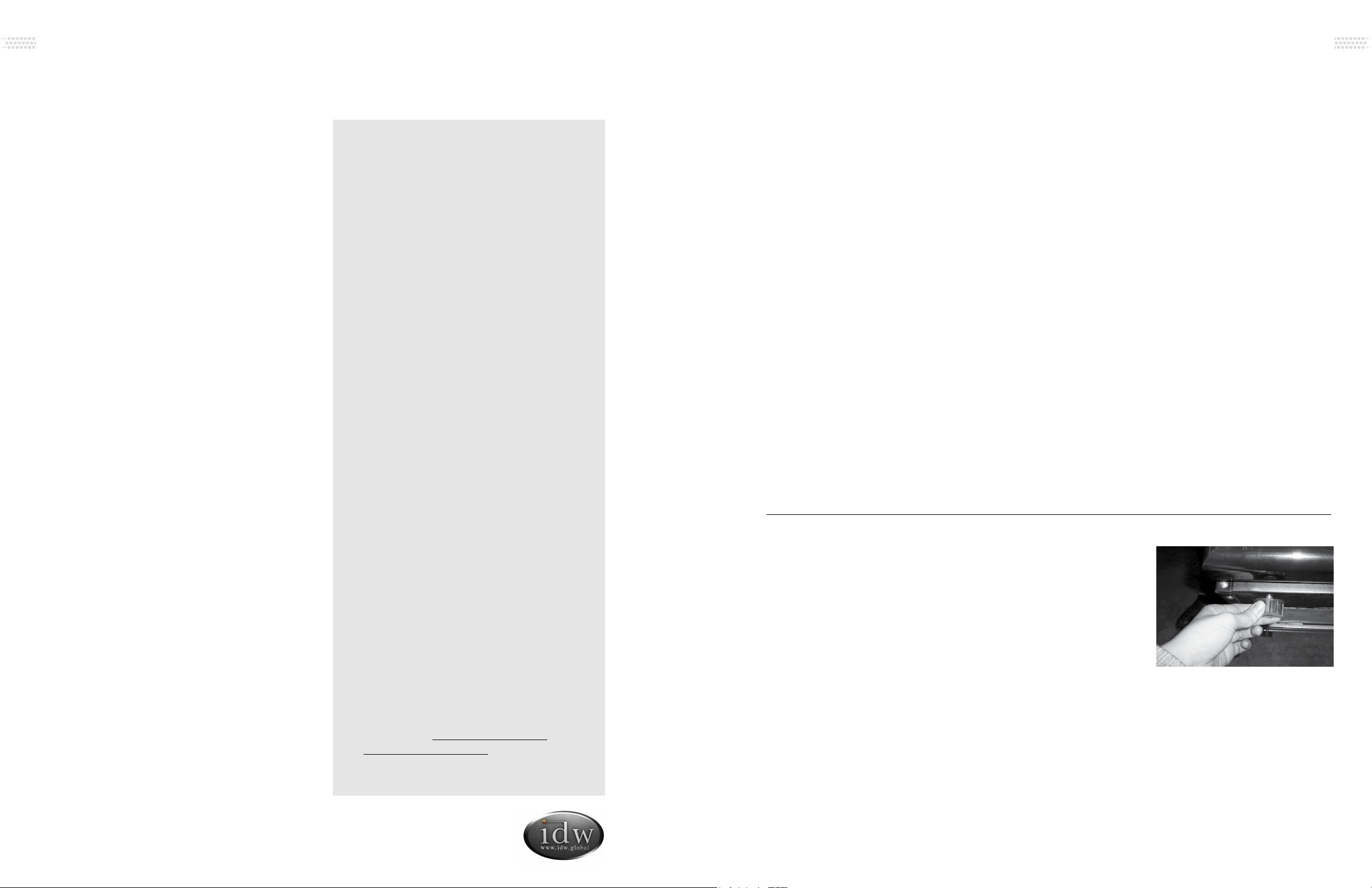
LEVELING LEG CLEANING
• Use a cloth to clean
leveling legs.
UNDER CABINET CLEANING
• Before starting, unplug the
power cord to make sure
the cooler is powered off.
• Once nished, plug the
cooler power cord back in.
Main Leveling Legs
• Tilt the cooler back and
use cloth to clean the
bottom of cabinet.
Front Supporting Leg
• Use the cloth to also clean
the compressor base
board. Then level the
cooler.
Instruction Manual G-2.5/GS-2.5 G-3/G-S3
6 7Innovative DisplayWorks, Inc.

SHELVING INSTALLATION
Shelf clips should be level so
shelf lays fl at.
Shelves are secured in place
with zip ties. Cut zip ties to
adjust shelves as desired.
Securely insert shelf clips into
pilasters.
(Maximum load per shelf is lbs/ kg)
Display refrigerators can be loaded within the shelf dimensions from the front
to back side. They can also be loaded in any space from the bottom to the top
interior cabinet. Do not allow product to block the evaporator fan cover because
the evaporator fan helps the cooler to ventilate properly.
Display refrigerators can be loaded within the shelf dimensions from the front
to back side. They can also be loaded in any space from the bottom to the top
interior cabinet. Do not allow product to block the evaporator fan cover because
the evaporator fan helps the cooler to ventilate properly.
Display refrigerators can be loaded within the shelf dimensions from the front
to back side. They can also be loaded in any space from the bottom to the top
interior cabinet. Do not allow product to block the evaporator fan cover because
the evaporator fan helps the cooler to ventilate properly.
Display refrigerators can be loaded within the shelf dimensions from the front
to back side. They can also be loaded in any space from the bottom to the top
interior cabinet. Do not allow product to block the evaporator fan cover because
the evaporator fan helps the cooler to ventilate properly.
Display refrigerators can be loaded within the shelf dimensions from the front
to back side. They can also be loaded in any space from the bottom to the top
interior cabinet. Do not allow product to block the evaporator fan cover because
the evaporator fan helps the cooler to ventilate properly.
[Model(s)] maximum load per shelf is lbs/ kg
[Model(s)] maximum load per shelf is lbs/ kg
[Model(s)] maximum load per shelf is lbs/ kg
[Model(s)] maximum load per shelf is lbs/ kg
[Model(s)] maximum load per shelf is lbs/ kg
[Model(s)] maximum load per shelf is lbs/ kg
[Model(s)] maximum load per shelf is lbs/ kg
[Model(s)] maximum load per shelf is lbs/ kg
[Model(s)] maximum load per shelf is lbs/ kg
[Model(s)] maximum load per shelf is lbs/ kg
[Model(s)] maximum load per shelf is lbs/ kg
[Model(s)] maximum load per shelf is lbs/ kg
[Model(s)] maximum load per shelf is lbs/ kg
[Model(s)] maximum load per shelf is lbs/ kg
• Serial number from the interior wall of the
cooler
• Coolers’ installation address and contact
information
• Installation location hours and operation
• Nature of problem
• Any reports of power interruptions
• Recent service or maintenance completed
on the cooler
• Has the cooler been relocated from original
installation location
• Clear access to the cooler
• Coolers’ instruction manual
Information to provide to your qualifi ed service professional:
Situation Causes
Liquid fl owing noise within cooler • This is the sound of the cooling agent fl owing through the pipes.
Refrigeration system is shutdown for longer periods
of time while temperature inside is still very low
• This refrigerator is well insulated and can maintain a relatively
ambient temperature.
Condensation on door/lid • This may be due to a high indoor humidity or the cooler’s
temperature is set too low. Wipe the door dry with a towel.
Issues Solutions
Cooler is not working properly Please check power supply:
• Check the electrical outlet for power, and that the plug is properly inserted.
• Check to see if the circuit breaker is tripped or the fuse is blown.
• Check if the condenser is free of dirt and debris.
• Check for low voltage
Cooler is not keeping product cool • Provide ample space between all products to ensure proper circulation of air.
• Keep unit away from direct sunlight or other heating source.
• Keep the door closed as often as possible.
• Be certain the cooler is not touching external objects or walls.
Excessive noise • Be certain the cooler is placed on a level surface.
• Be certain the cooler is not touching external objects or walls.
Compressor turns on and off frequently • The room temperature is higher than normal.
• The door is not closed completely.
• The door gasket is not sealed properly.
• There is insuf cient clearance around the cooler.
• The thermostat is not set properly.
• The frequency of cycling will be reduced when all of the product reaches the
set temperature.
TROUBLESHOOTING
The following are NOT malfunctions:
1This refrigerator has been designed and manufactured according to National standards. If there
are any questions during use, refer to this operation manual to help troubleshoot problems.
2 When disposing of the cooler, please remove the door/lid and lock assembly to avoid children
accidentally becoming trapped inside the cooler.
Prior to calling service, check the following:
AFTER SALES SERVICE
Any product has the possibility of malfunction. Please observe the cooler’s operation and any
changes to product being stored. If there are any abnormal cases, refer to the table below. If there
is still no change after following the below instructions, please inform our service center in a timely
manner to avoid a further loss of the unit.
Display refrigerators can be loaded within the shelf dimensions from the front
to back side. They can also be loaded in any space from the bottom to the top
interior cabinet. Do not allow product to block the evaporator fan cover because
the evaporator fan helps the cooler to ventilate properly.
G2.5/GS-2.5 maximum load per shelf is 26 lbs/11.8 kg
G-3/GS-3 maximum load per shelf is 34 lbs/15.4221 kg
Instruction Manual G-2.5/GS-2.5 G-3/G-S3
8 9Innovative DisplayWorks, Inc.
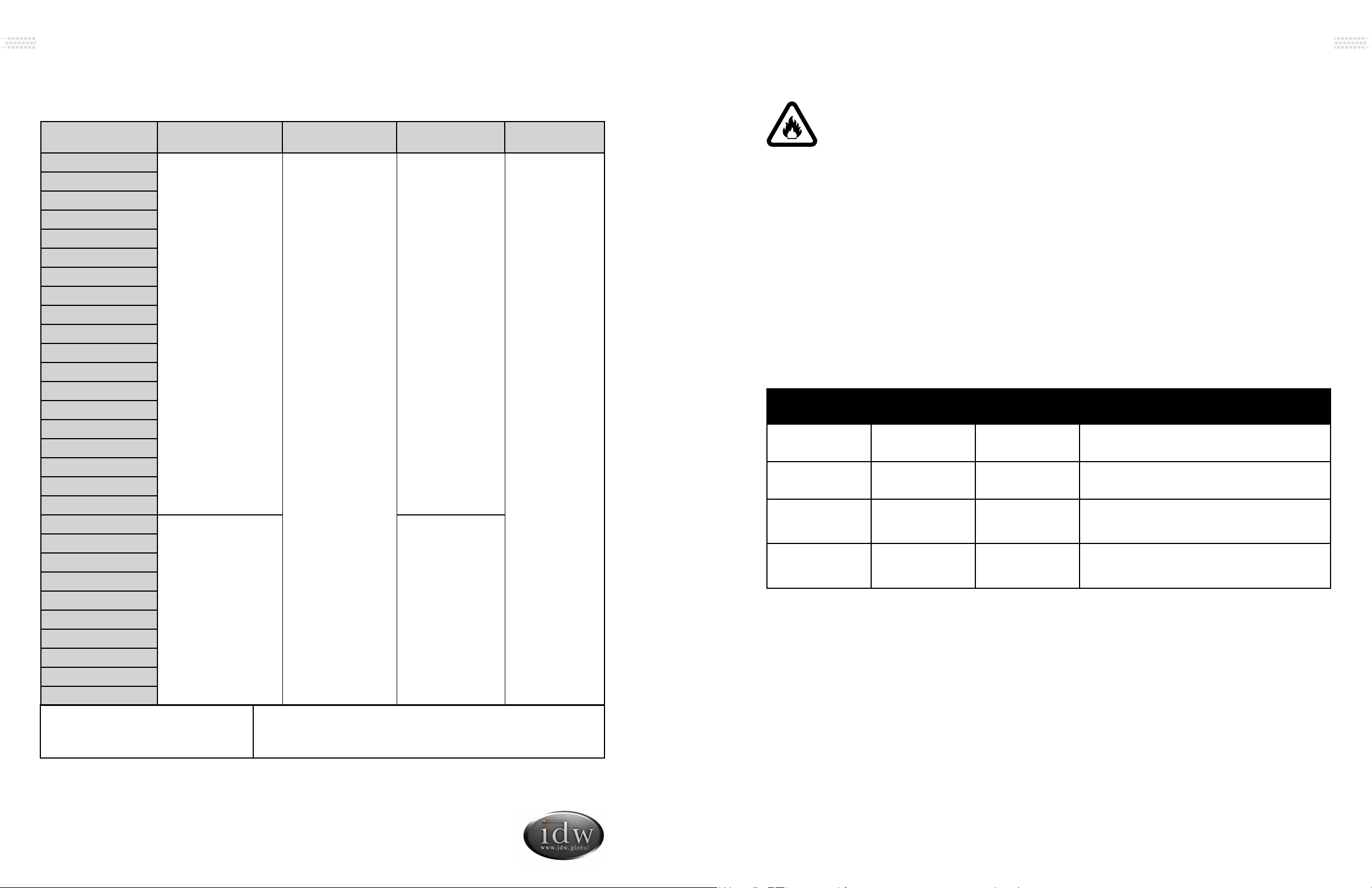
SPECIFICATIONS CAUTION FLAMMABLE REFRIGERANT
• DANGER – Risk Of Fire Or Explosion. Flammable Refrigerant Used. To Be Repaired
Only By Trained Service Personnel. Do Not Puncture Refrigerant Tubing.
• CAUTION – Risk Of Fire Or Explosion. Flammable Refrigerant Used. Consult Repair
Manual/Owner’s Guide Before Attempting To Install or Service This Product. All Safety
Precautions Must be Followed.
• CAUTION – Risk Of Fire Or Explosion. Dispose Of Properly In Accordance With
Federal Or Local Regulations. Flammable Refrigerant Used.
• CAUTION – Risk Of Fire Or Explosion Due To Puncture Of Refrigerant Tubing; Follow
Handling Instructions Carefully. Flammable Refrigerant Used.
• CAREFUL - Handling, moving and operating of the refrigerator or freezer to avoid
either damaging the refrigerant tubing, or increasing the risk of a leak.
• CAUTION - Component parts shall be replaced with like components and that
servicing shall be done by factory authorized service personnel, so as to minimize the
risk of possible ignition due to incorrect parts or improper service.
DANGER – Risk Of Fire Or Explosion. Flammable Refrigerant Used. To Be
Repaired By Trained Service Personnel Only. Do Not Puncture Refrigerant Tubing.
CAUTION – Risk Of Fire Or Explosion. Flammable Refrigerant Used. Consult
Repair Manual/Owner’s Guide Before Attempting To Service This Product. All
Safety Precautions Must be Followed.
CAUTION – Risk Of Fire Or Explosion. Dispose Of Property In Accordance With
Federal Or Local Regulations. Flammable Refrigerant Used.
CAUTION – Risk Of Fire Or Explosion Due To Puncture Of Refrigerant Tubing;
Follow Handling Instructions Carefully. Flammable Refrigerant Used.
CAUTION FLAMMABLE - R600a Refrigerant
DANGER - Risque d'incendie ou d'explosion. Réfrigérant inflammable utilisé.
Pour être réparé que par un personnel de maintenance qualifié. Ne pas percer
réfrigérant Tubing.
ATTENTION - Risque d'incendie ou d'explosion. Réfrigérant inflammable utilisé.
Consultez manuel / guide de l 'utilisateur de réparation avant de tenter de
réparer ce produit. Toutes les précautions de sécurité doivent être respectées.
ATTENTION - Risque d'incendie ou d'explosion. Aliéner des biens conformé-
ment à la réglementation fédérales ou locales. Réfrigérant inflammable utilisé.
ATTENTION - Risque d'incendie ou une explosion due à la perforation de
tuyaux de réfrigérant; suivre les instructions de manipulation avec précaution.
Réfrigérant inflammable utilisé.
PRUDENCE INFLAMMABLE - R600a Réfrigérant
Switch Status Door Side
Light Switch
Door Logo
Light Switch Remark
I / I ON ON Door Lights ON and Door logo ON
I / O ON OFF Door Lights ON and Door logo OFF
O / I OFF ON Door Lights OFF and Door logo ON,
Door Lights turn ON when door opens
O / O OFF OFF Door Lights OFF and Door logo OFF,
Door Lights turn ON when door opens
MODEL VOLUME(L)
RATED
VOLTAGE
RATED
CURRENT REFRIGERANT
GS-2.5-N234B
69.37
110V/60Hz
2A
R600a
GS-2.5-W234B
GS-2.5-B234B
GS-2.5-P234B
GS-2.5-LN234B
GS-2.5-LW234B
GS-2.5-LB234B
GS-2.5-LP234B
GS-2.5-0234B
GS-2.5-L0234B
GS-2.5-2234B
GS-2.5-2W234B
GS-2.5-2B234B
GS-2.5-2P234B
GS-2.5-L2W234B
GS-2.5-L2B234B
GS-2.5-L2P234B
GS-2.5-A234B
GS-2.5-LA234B
GS-3-N234B
98.5 1.4A
GS-3-W234B
GS-3-B234B
GS-3-P234B
GS-3-0234B
GS-3-2234B
GS-3-A234B
GS-3-2W234B
GS-3-2B234B
GS-3-2P234B
Instruction Manual G-2.5/GS-2.5 G-3/G-S3
10 11Innovative DisplayWorks, Inc.
NSF/ASNI-7: Type II Display Refrigerator A display refrigerator intended for use in an area where the
environmental conditions are controlled and maintained so that the
ambient temperature does not exceed 80°F (27°C).

XP - Plug
G - Start Relay
L1, L2 - LED Lamp
T - Transformer
M1 - Evaporator Fan
M2 - Condenser Fan
CO - Compressor
E - Overload Protector
SAT - Thermostat
IL - Magnetism Switch
S1 - Door LED Switch
S2 - Sidepiece LED Switch
XP - Plug
G - Start Relay
L1 - LED Lamp
T - Transformer
M1 - Evaporator Fan
M2 - Condenser Fan
CO - Compressor
E - Overload Protector
SAT - Thermostat
IL - Magnetism Switch
S2 - Sidepiece LED Switch
XP - Plug
G - Start Relay
L1, L2 - LED Lamp
T - Transformer
M1 - Evaporator Fan
M2 - Condenser Fan
CO - Compressor
E - Overload Protector
SAT - Thermostat
IL - Magnetism Switch
S1 - Door LED Switch
S2 - Sidepiece LED Switch
XP - Plug
G - Start Relay
L1 - LED Lamp
T - Transformer
M1 - Evaporator Fan
M2 - Condenser Fan
CO - Compressor
E - Overload Protector
SAT - Thermostat
IL - Magnetism Switch
S2 - Sidepiece LED Switch
CIRCUIT DIAGRAM
GS-2.5-N234B, GS-2.5-W234B, GS-2.5-B234B,GS-2.5-P234B,
GS-2.5-LN234B, GS-2.5-LW234B, GS-2.5-LB234B,GS-2.5-LP234B
CIRCUIT DIAGRAM
GS-2.5-0234B, GS-2.5-L0234B
XP - Plug
G - Start Relay
L1, L2 - LED Lamp
T - Transformer
M1 - Evaporator Fan
M2 - Condenser Fan
CO - Compressor
E - Overload Protector
SAT - Thermostat
IL - Magnetism Switch
S1 - Door LED Switch
S2 - Sidepiece LED Switch
XP - Plug
C - Control Panel
G - Start Relay
L1, L2 - LED Lamp
T - Transformer
M1 - Evaporator Fan
M2 - Condenser Fan
CO - Compressor
E - Overload Protector
SAT - Thermostat
IL - Magnetism Switch
S1 - Door LED Switch
S2 - System Control Switch
XP - Plug
G - Start Relay
L1, L2 - LED Lamp
T - Transformer
M1 - Evaporator Fan
M2 - Condenser Fan
CO - Compressor
E - Overload Protector
SAT - Thermostat
IL - Magnetism Switch
S1 - Door LED Switch
S2 - Sidepiece LED Switch
XP - Plug
C - Control Panel
G - Start Relay
L1, L2 - LED Lamp
T - Transformer
M1 - Evaporator Fan
M2 - Condenser Fan
CO - Compressor
E - Overload Protector
SAT - Thermostat
IL - Magnetism Switch
S1 - Door LED Switch
S2 - System Control Switch
CIRCUIT DIAGRAM
GS-2.5-2234B, GS-2.5-2W234B,GS-2.5-2B234B,GS-2.5-2P234B,
GS-2.5-L2W234B,GS-2.5-L2B234B,GS-2.5-L2P234B
CIRCUIT DIAGRAM
GS-2.5-A234B, GS-2.5-LA234B
XP - Plug
G - Starter
L1, L2 - LED Lamp
T - Transformer
M1 - Evaporator Fan
M2 - Condenser Fan
CO - Compressor
E - Overload Protector
SAT - Thermostat
IL - Magnetism Switch
S1 - Door LED Switch
S2 - Sidepiece LED Switch
XP - Plug
G - Starter
L1, L2 - LED Lamp
T - Transformer
M1 - Evaporator Fan
M2 - Condenser Fan
CO - Compressor
E - Overload Protector
SAT - Thermostat
IL - Magnetism Switch
S1 - Door LED Switch
S2 - Sidepiece LED Switch
XP - Plug
C - Control Panel
G - Starter
L1, L2 - LED Lamp
T - Transformer
M1 - Evaporator Fan
M2 - Condenser Fan
CO - Compressor
E - Overload Protector
SAT - Thermostat
IL - Magnetism Switch
S1 - Door LED Switch
S2 - System Control LED Switch
XP - Plug
G - Starter
L1 - LED Lamp
T - Transformer
M1 - Evaporator Fan
M2 - Condenser Fan
CO - Compressor
E - Overload Protector
SAT - Thermostat
IL - Magnetism Switch
S2 - Sidepiece LED Switch
Instruction Manual G-2.5/GS-2.5 G-3/G-S3
12 13Innovative DisplayWorks, Inc.

CIRCUIT DIAGRAM
GS-3-0234B
CIRCUIT DIAGRAM
GS-3-N234B, GS-3-W234B,GS-3-B234B, GS-3-P234B
CIRCUIT DIAGRAM
GS-3-2234B, GS-3-A234B, GS-3-2W234B, GS-3-2B234B, GS-3-2P234B
S
XP L
N
Io
IL
S
L
1
L
t
CO
G
E
SAT
T
2
I
1
M
M
I
2
M
M
1 2
XP - Plug
G - Start Relay
L1, L2 - LED Lamp
T - Transformer
M1 - Evaporator Fan
M2 - Condenser Fan
CO - Compressor
E - Overload Protector
SAT - Thermostat
IL - Magnetism Switch
S1 - Door Side Light Switch
S2 - Logo Light Switch
XP - Plug
G - Start Relay
L1, L2 - LED Lamp
T - Transformer
M1 - Evaporator Fan
M2 - Condenser Fan
CO - Compressor
E - Overload Protector
SAT - Thermostat
IL - Magnetism Switch
S1 - Door Side Light Switch
S2 - Logo Light Switch
XP - Plug
G - Start Relay
L - LED Lamp
T - Transformer
M1 - Evaporator Fan
M2 - Condenser Fan
CO - Compressor
E - Overload Protector
SAT - Thermostat
IL - Magnetism Switch
S - Door Side Light Switch
XP L
N
Io
IL
S
L
t
CO
G
E
SAT
T
I
1
M
M
I
2
M
M
S
XP L
N
Io
IL
S
L
1
L
t
CO
G
E
SAT
T
I
1
M
M
I
2
M
M
2
1 2
S
XP L
N
Io
IL
S
L
1
L
t
CO
G
E
SAT
T
2
I
1
M
M
I
2
M
M
1 2
XP - Plug
G - Start Relay
L1, L2 - LED Lamp
T - Transformer
M1 - Evaporator Fan
M2 - Condenser Fan
CO - Compressor
E - Overload Protector
SAT - Thermostat
IL - Magnetism Switch
S1 - Door Side Light Switch
S2 - Logo Light Switch
XP - Plug
G - Start Relay
L1, L2 - LED Lamp
T - Transformer
M1 - Evaporator Fan
M2 - Condenser Fan
CO - Compressor
E - Overload Protector
SAT - Thermostat
IL - Magnetism Switch
S1 - Door Side Light Switch
S2 - Logo Light Switch
XP - Plug
G - Start Relay
L - LED Lamp
T - Transformer
M1 - Evaporator Fan
M2 - Condenser Fan
CO - Compressor
E - Overload Protector
SAT - Thermostat
IL - Magnetism Switch
S - Door Side Light Switch
XP L
N
Io
IL
S
L
t
CO
G
E
SAT
T
I
1
M
M
I
2
M
M
S
XP L
N
Io
IL
S
L
1
L
t
CO
G
E
SAT
T
I
1
M
M
I
2
M
M
2
1 2
XP - Plug
G - Starter
L1, L2 - LED Lamp
T - Transformer
M1 - Evaporator Fan
M2 - Condenser Fan
CO - Compressor
E - Overload Protector
SAT - Thermostat
IL - Magnetism Switch
S1 - Door Side Light Switch
S2 - Logo Light Switch
XP - Plug
G - Starter
L1, L2 - LED Lamp
T - Transformer
M1 - Evaporator Fan
M2 - Condenser Fan
CO - Compressor
E - Overload Protector
SAT - Thermostat
IL - Magnetism Switch
S1 - Door Side Light Switch
S2 - Logo Light Switch
XP - Plug
G - Starter
L - LED Lamp
T - Transformer
M1 - Evaporator Fan
M2 - Condenser Fan
CO - Compressor
E - Overload Protector
SAT - Thermostat
IL - Magnetism Switch
S - Door Side Light Switch
Instruction Manual G-2.5/GS-2.5 G-3/G-S3
14 15Innovative DisplayWorks, Inc.

Innovative DisplayWorks, Inc.
To locate the distributor in your area go to: http://www.idw.global/contact/#distributors
Other manuals for G-Series
12
This manual suits for next models
29
Table of contents
Other IDW Accessories manuals


Popular Accessories manuals by other brands


SICK
SICK WLD26 operating instructions

United Technologies
United Technologies interlogix RF620I4 installation instructions

PERMASTEEL
PERMASTEEL PS-206-SS Use & care guide

Sandstrom
Sandstrom S6PB10KC17 instruction manual

Telco Sensors
Telco Sensors Space Scan Series user manual

Denon Professional
Denon Professional Fitness Pack quick start guide