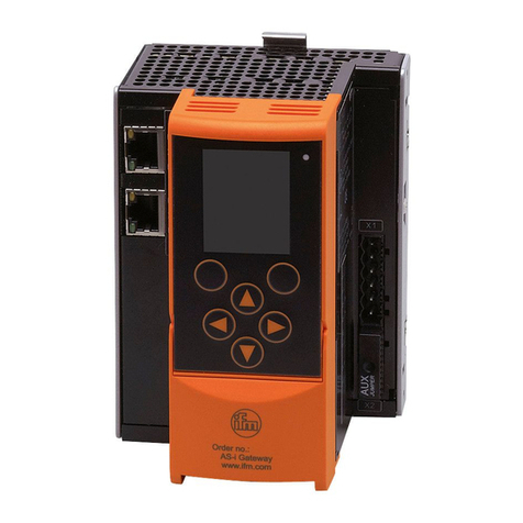
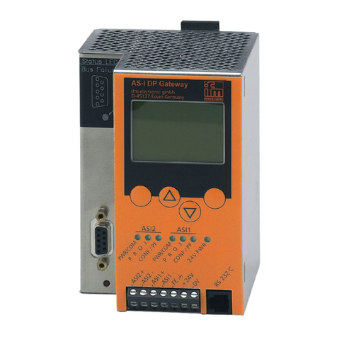
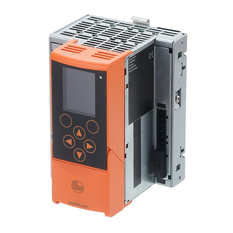
IFM AC1401 User manual

Operating instructions
AS-i Profinet gateway
AC1401 / AC1402
7390832/00 04/2014
UK

2
Contents
1 Preliminary note���������������������������������������������������������������������������������������������������4
1�1 Notes on this document���������������������������������������������������������������������������������4
1�2 Symbols used ������������������������������������������������������������������������������������������������4
2 Safety instructions �����������������������������������������������������������������������������������������������4
2�1 General����������������������������������������������������������������������������������������������������������4
2�2 Installation and connection ����������������������������������������������������������������������������4
2�3 Tampering with the device �����������������������������������������������������������������������������5
3 Functions and features ����������������������������������������������������������������������������������������5
3�1 Configuration interface X3 �����������������������������������������������������������������������������5
3�2 Fieldbus interface X6 and X7 ������������������������������������������������������������������������5
3�3 Electrical supply���������������������������������������������������������������������������������������������5
4 Installation������������������������������������������������������������������������������������������������������������6
5 Electrical connection��������������������������������������������������������������������������������������������6
5�1 Device supply �����������������������������������������������������������������������������������������������6
5�1�1 Device supply via AUX, AS-i supply via AS-i power supply ������������������6
5�1�2 Device and AS-i supply via the AS-i power supply �������������������������������7
5�1�3 Device and AS-i supply via one common power supply �����������������������7
5�2 Wiring�������������������������������������������������������������������������������������������������������������8
6 Operating and display elements ��������������������������������������������������������������������������9
6�1 Operating elements ���������������������������������������������������������������������������������������9
6�2 LED displays������������������������������������������������������������������������������������������������10
6�2�1 Device LED H1 �����������������������������������������������������������������������������������10
6�2�2 Ethernet LEDs H2 and H4 ������������������������������������������������������������������10
6�2�3 Connection LEDs H3 and H5 ������������������������������������������������������������� 11
7 Operation����������������������������������������������������������������������������������������������������������� 11
7�1 Settings�������������������������������������������������������������������������������������������������������� 11
7�1�1 Language selection ���������������������������������������������������������������������������� 11
7�2 Navigation����������������������������������������������������������������������������������������������������12
7�2�1 Navigation elements ���������������������������������������������������������������������������12
7�2�2 Pictograms and main navigation ��������������������������������������������������������13
8 Diagnostics ��������������������������������������������������������������������������������������������������������14
9 Technical data����������������������������������������������������������������������������������������������������14

3
UK
9�1 Data sheets �������������������������������������������������������������������������������������������������14
9�2 Programming manual ����������������������������������������������������������������������������������14
10 Maintenance, repair and disposal��������������������������������������������������������������������14
11 Approvals/standards ����������������������������������������������������������������������������������������15
12 Scale drawing ��������������������������������������������������������������������������������������������������15

4
1 Preliminary note
1.1 Notes on this document
This document applies to devices of the type „AS-i Profinet gateway“ (art� no�:
AC1401 /AC1402)�
It is part of the device and contains information about the correct handling of the
product�
This document is intended for qualified electricians� These specialists are people
who are qualified by their training and their experience to see and to avoid
possible hazards that may be caused during operation of the device�
►Read this document before using the device�
►Keep this document during the service life of the device�
1.2 Symbols used
►Instructions
> Reaction, result
[…] Designation of pushbuttons, buttons or indications
→Cross-reference
Important note
Non-compliance can result in malfunction or interference�
Information
Supplementary note
2 Safety instructions
2.1 General
►Observe these operating instructions�
►Adhere to the warning notes on the product�
Non-observance of the instructions, operation which is not in accordance with use
as prescribed below, wrong installation or incorrect handling can affect the safety
of operators and machinery�
2.2 Installation and connection
The device must only be installed, connected and put into operation by a qualified
electrician as the safe function of the device and machinery is only guaranteed
when installation is correctly carried out�

5
UK
The installation and connection must comply with the applicable national and
international standards� Responsibility lies with the person installing the device�
This is a class A product� The unit may cause radio interference in domestic areas� In
this case it can be necessary for the user to take appropriate measures�
2.3 Tampering with the device
Tampering with the device is not allowed and will lead to an exclusion of liability
and warranty� Tampering with the device can affect the safety of operators and
machinery�
►Do not open the device�
►Do not insert any objects into the device�
►Prevent metal foreign bodies from penetrating�
3 Functions and features
The AS-i Profinet gateway includes one (AC1401) or two (AC1402) AS-i masters,
one WEB server and a Profinet interface with 2-port switch�
• It controls the exchange of data to the sensor / actuator level�
• It communicates with the superior control level via Profinet�
• It visualises sensor/actuator data on the integrated WEB server�
• It allows device configuration via the WEB server�
3.1 Configuration interface X3
• 10 Mbps and 100 Mbps
• TCP/IP - Transport Control Protocol/ Internet Protocol
• UDP - User Datagram Protocol
• IT functionality: HTTP server
• RJ45, Twisted-Pair
3.2 Fieldbus interface X6 and X7
• Profinet RT device class B incl� MRP protocol (Media Redundancy Protocol)
• 100 Mbps
3.3 Electrical supply
• the unit can be supplied either from 24 V (AUX) or from AS-i
• AS-i power 24 V compatible

6
4 Installation
►Fix the AS-i Profinet gateway onto a 35 mm DIN rail�
The protection rating of the unit is IP 20, therefore it should be mounted in a
protected location (e�g� control cabinet)�
Ensure a condensation-free environment� Avoid excessive dust, vibration
and shock� The air circulation through the vents must not be impeded�
Avoid installation in direct vicinity of frequency inverters or other interfering
sources�
5 Electrical connection
The device must be connected by a qualified electrician�
►Disconnect power before connecting the device�
►Observe the national and international regulations for the installation of
electrical equipment�
►Connect the device as indicated on the terminals�
►Ensure an electrical connection between the AS-i Profinet gateway
(terminal FE) and the ground of the installation�
►Only insert or remove the AUX jumper when the device is disconnected�
Otherwise, a device failure may occur�
5.1 Device supply
To operate an AS-i system, an AS-i power supply (e�g� AC1236) or the
data decoupling module AC1250 (not supplied) with a DC power supply is
required�
►Supply the device with one of the following versions�
5.1.1 Device supply via AUX, AS-i supply via AS-i power supply
►Supply the device with a voltage of 24 V DC (18���32 V PELV) (e�g� from the
24 V DN3011 power supply of ifm electronic)� The connection is made to the
terminals X2�
►Pull out the AUX jumper�
►To supply the AS-i lines, connect the terminals X1 to one or two AS-i power
supplies (AC1401: one AS-i master, AC1402: two AS-i masters)�

7
UK
►Ensure a low-resistance connection of the symmetry point of the device
(terminal X1�5 FE) to the ground of the installation�
5.1.2 Device and AS-i supply via the AS-i power supply
►To supply the AS-i lines connect the terminals X1 to one or two AS-i power
supplies (AC1401: one AS-i master, AC1402: two AS-i masters)�
►Ensure a low-resistance connection of the symmetry point of the device
(terminal X1�5 FE) to the ground of the installation�
The AUX jumper is plugged onto the connector X2 (factory setting), the
device is supplied via AS-i line 1 (x1�3 and S1�4)�
5.1.3 Device and AS-i supply via one common power supply
►Plug the data decoupling module AC1250 (not supplied) into the terminals X1
and X2 to supply the device and the connected AS-i lines�
►Ensure a low-resistance connection of the data decoupling (terminal „FE“) to
the ground of the installation�
The gateway and both AS-i lines are supplied via one power supply (PELV
21�5 V���31�6 V AS-i or AUX)� The AS-i lines have a thermal short-circuit protection
(4A)�

8
Several gateways can be supplied by one powerful power supply�
5.2 Wiring
Terminal X1 Combicon 5�08 Pin Description
AS-i 2 + 1 AS-i + for AS-i line 2
AS-i 2 - 2 AS-i - for AS-i line 2
AS-i 1 + 3 AS-i + for AS-i line 1
AS-i 1 - 4 AS-i - for AS-i line 1
FE 5 Functional earth
Terminal X2 Combicon 5�08
or AUX jumper
Pin Description
24 V 1 +24 V device supply
0 V 2 +0 V device supply
Terminal X3 RJ 45 Configuration interface
Terminal X6 RJ 45 Profinet interface 2
Terminal X7 RJ 45 Profinet interface 1

9
UK
6 Operating and display elements
6.1 Operating elements
1: LEDs H1
2: LEDs H2 / H4
3: Pronet interface 2 (RJ 45)
4: Pronet interface 1 (RJ 45)
5: LEDs H3 / H5
6: Navigation buttons
7: Softkeys
8: Combicon connector

10
1: Slot for SD cards
2: Conguration interface (RJ45)
6.2 LED displays
6.2.1 Device LED H1
A diagnostic LED on the Profinet / AS-i gateway informs you of the state of the
device and the connected systems�
LED status Description
The green LED is lit: > Device has been started
> There is no warning message
> There is no error message
Yellow LED flashes slowly (0�5 Hz): > There is a warning message
> There is no error message
Red LED flashes quickly (2 Hz): > There is an error message
6.2.2 Ethernet LEDs H2 and H4
LED status Description
Yellow LED flashes: Receipt of data

11
UK
6.2.3 Connection LEDs H3 and H5
LED status Description
The green LED is lit: Physical connection ok
7 Operation
7.1 Settings
During operation the display is switched off after 10 minutes without
operation�
►Activate the display by pressing any desired button�
7.1.1 Language selection
► Change the user language of the device by pressing the ► button and the ▲
button or ▼ button simultaneously.

12
7.2 Navigation
7.2.1 Navigation elements
xxx xxx
#
xxx
1: User level
2: Focus
3: Operating area
4: Softkey labelling
5: Navigation compass
6: Navigation status bar
7: Main navigation bar
8: Info bar

13
UK
7.2.2 Pictograms and main navigation
Quicksetup (Summary of the menu points required for a basic
configuration)
• Project all
Projection adaptation for AS-i master 1 and AS-i master 2 (only AC1402)
• Operating mode
Selection of the operating modes for
- AS-i master 1,
- AS-i master 2 (only AC1402),
- system (gateway, manual)
• fieldbus
- display / modify the parameters of the Profinet interface
- IP address
- Subnet mask
- Gateway address
• Configuration interface
- Display / modify the parameters of the Ethernet configuration interface
- DHCP
- IP address
- Subnet mask
- Gateway address
• Addressing 1
- Slave overview AS-i line 1 (with the option to change AS-i addresses)
• Addressing 2
- Slave overview AS-i line 2 (with the option to change AS-i addresses)
AS-i 1
• AS-i master settings
• AS-i diagnosis
• AS-i slaves
AS-i 2
• AS-i master settings
• AS-i diagnosis
• AS-i slaves
System
• Information
• Settings
• Diagnostics

14
Interfaces
• Settings and information of the configuration interface
• Settings and information of the Profinet interface
Further details see programming manual → chapter 9.2
8 Diagnostics
Any warning or error message is indicated in the display of the device� The
pictogram of the function unit concerned is superposed by a warning or error
symbol� If for one function unit a warning and an error message exist at the same
time, only the error symbol is displayed�
Warning message
Error message
9 Technical data
9.1 Data sheets
Data sheets can be found at www�ifm�com�
9.2 Programming manual
The programming manual can be found at www�ifm�com�
10 Maintenance, repair and disposal
►Replace the buffer battery of the real-time clock as required, type CR2032
►Dispose of the device in accordance with the national environmental
regulations�

15
UK
11 Approvals/standards
The EC declaration of conformity and approvals can be found at
www�ifm�com�
12 Scale drawing
106,293
135,5
128,2
Other manuals for AC1401
2
This manual suits for next models
1
Table of contents
Other IFM Gateway manuals
Popular Gateway manuals by other brands

WAGO
WAGO 758-916 manual

Western Reserve Controls
Western Reserve Controls 1782-JDC user manual

Pelican
Pelican GW400-LTE installation guide

DELTA GROUP
DELTA GROUP EnOcean O3-DIN Application guide

CTI Products
CTI Products RadioPro installation guide

Viessmann
Viessmann WAGO BACnet/IP Installation and service instructions