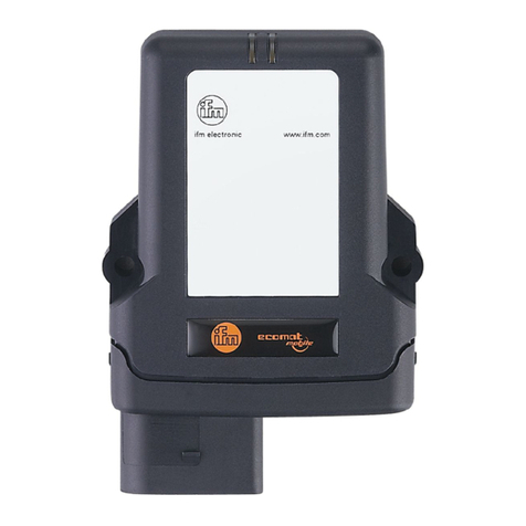
IFM AIK050 User manual

>
>
80294077 / 00
07/2020
Operating Instructions
io-
key
AIK050
English

io-key
2
Contents
1Preliminary note 4
1.1 Legal and copyright information...........................................................................................4
1.2 Symbols used.......................................................................................................................4
1.3 Warnings used .....................................................................................................................5
1.4 Modification history ..............................................................................................................5
2Safety instructions 6
2.1 General ................................................................................................................................6
2.2 IT security.............................................................................................................................6
2.3 Required background knowledge ........................................................................................6
3Functions and features 7
4Function 8
4.1 IO-Link..................................................................................................................................8
4.1.1 IO-Link supply ..............................................................................................................................8
4.2 Gateway ...............................................................................................................................8
4.3 Mobile radio..........................................................................................................................9
4.3.1 Supported wireless standards ......................................................................................................9
4.3.2 Countries covered ........................................................................................................................9
4.3.3 Data transmission.........................................................................................................................9
4.3.4 SIM card.......................................................................................................................................9
4.4 Digital outputs ....................................................................................................................10
4.5 edge alarm function ...........................................................................................................10
4.6 Edge switching function .....................................................................................................11
4.6.1 edge threshold function ..............................................................................................................12
4.6.2 edge window function.................................................................................................................13
5Operating and display elements 14
5.1 LED indicators....................................................................................................................14
5.1.1 Voltage supply............................................................................................................................14
5.1.2 Mobile radio................................................................................................................................14
5.1.3 IO-Link ports (Class A) ...............................................................................................................14

io-key
3
6Mounting 15
6.1 Installing the device ...........................................................................................................15
7Electrical connection 16
7.1 Connecting IO-Link devices ...............................................................................................16
7.2 Connecting switching outputs ............................................................................................17
7.3 Connecting the device .......................................................................................................17
8Set-up 18
8.1 Initial installation.................................................................................................................18
8.2 Mounting and connecting the AIK050 ................................................................................18
8.3 Connecting the IO-Link devices .........................................................................................19
9Fault detection 20
10 Maintenance, repair and disposal 21
10.1 Cleaning process ...............................................................................................................21
10.2 Firmware update ................................................................................................................21
11 Approvals and standards 22
12 Scale drawing 23
13 Accessories 24
14 Appendix 25
14.1 Security ..............................................................................................................................26
14.1.1 Mobile data transmission............................................................................................................26
14.1.2 Data storage and data processing..............................................................................................26
14.1.3 Data transmission from the cloud to the customer .....................................................................26
14.1.4 User administration and access control......................................................................................27
14.2 Invoicing .............................................................................................................................28
14.2.1 Hardware....................................................................................................................................28
14.2.2 Interval-related services .............................................................................................................28
14.3 Contract terminations or amendments...............................................................................29
14.4 Frequencies and Maximum Permissible Error...................................................................30
14.5 Operation of the servers and system components ............................................................32
14.5.1 System components...................................................................................................................32
14.5.2 Maintenance of servers and system components ......................................................................32
14.6 Service availability .............................................................................................................33
14.6.1 Excluded downtime ....................................................................................................................33
14.6.2 Restrictions.................................................................................................................................33
14.6.3 Changes.....................................................................................................................................34
15 Index 35

io-key
4
1 Preliminary note
Content
Legal and copyright information ...............................................................................................................4
Symbols used ...........................................................................................................................................4
Warnings used..........................................................................................................................................5
Modification history...................................................................................................................................5
33203
>
1.1 Legal and copyright information
59392
© All rights reserved by ifm electronic gmbh. No part of these instructions may be reproduced and
used without the consent of ifm electronic gmbh.
All product names, pictures, companies or other brands used on our pages are the property of the
respective rights owners.
>
1.2 Symbols used
58277
Important note
Non-compliance can result in malfunction or interference
Information
Supplementary note
►... Request for action
>... Reaction, result
→... "see"
abc Cross-reference
123
0x123
0b010
Decimal number
Hexadecimal number
Binary number
[...] Designation of pushbuttons, buttons or indications

io-key
5
>
1.3 Warnings used
58278
WARNING
Warning of serious personal injury.
Death or serious irreversible injuries may result.
CAUTION
Warning of personaly injury.
Slight reversible injuries may result.
NOTICE!
Warning of damage to property
>
1.4 Modification history
34492
Version Topic Date
00 New creation of document 07/2020

io-key
6
2 Safety instructions
Content
General .....................................................................................................................................................6
IT security .................................................................................................................................................6
Required background knowledge .............................................................................................................6
28333
>
2.1 General
58525
•The device described is a subcomponent for integration into a system. The manufacturer is
responsible for the safety of the system. The system manufacturer undertakes to perform a risk
assessment and to create documentation in accordance with legal and normative requirements to
be provided to the operator and user of the system. This documentation must contain all
necessary information and safety instructions for the operator, the user and, if applicable, for any
service personnel authorised by the manufacturer of the system.
•Read this document before setting up the product and keep it during the entire service life.
•The product must be suitable for the corresponding applications and environmental conditions
without any restrictions.
•Only use the product for its intended purpose (→Bestimmungsgemäße Verwendung).
•If the operating instructions or the technical data are not adhered to, personal injury and/or
damage to property may occur.
•The manufacturer assumes no liability or warranty for any consequences caused by tampering
with the product or incorrect use by the operator.
•Installation, electrical connection, set-up, programming, configuration, operation and maintenance
of the product must be carried out by personnel qualified and authorised for the respective activity.
•Protect units and cables against damage.
>
2.2 IT security
58235
NOTICE!
If the device is operated in an unprotected network environment:
>Unauthorised read or write access to data is possible.
>Unauthorised manipulation of the device function is possible.
►Check and restrict access options to the device.
>
2.3 Required background knowledge
34185
This document is intended for specialists. Specialists are people who, based on their relevant training
and experience, are capable of identifying risks and avoiding potential hazards that may be caused
during operation or maintenance of the product.
The document contains information about the correct handling of the product.

io-key
7
3 Functions and features
59393
The device may only be used for the following purposes:
•as IO-Link master to operate IO-Link devices
•as mobile radio gateway between IO-Link devices and the ifm cloud
The device is designed for use outside of a control cabinet.
►Only use the device within the limits of the technical data (→Technische Daten).

io-key
8
4 Function
Content
IO-Link ......................................................................................................................................................8
Gateway....................................................................................................................................................8
Mobile radio ..............................................................................................................................................9
Digital outputs .........................................................................................................................................10
edge alarm function ................................................................................................................................10
edge switching function ..........................................................................................................................11
33836
>
4.1 IO-Link
59394
The device offers the following IO-Link functions:
•IO-Link master (IO-Link revision 1.0 and 1.1)
•2 IO-Link Ports Class A to connect IO-Link devices. The IO-Link ports of the AIK050 meet the
requirements of the IO-Link specifications 1.0 to 1.1.2.
The AIK050 offers no function to configure the connected IO-Link devices.
►Configure IO-Link devices in accordance with the process requirements before connecting
them to the AIK050.
>
4.1.1 IO-Link supply
59395
The device has 2 supplies for IO-Link devices.
Every supply provides short circuit monitoring.
>
4.2 Gateway
59396
The device provides the process data of the connected IO-Link devices via mobile radio in the ifm
cloud.

io-key
9
>
4.3 Mobile radio
59397
>
4.3.1 Supported wireless standards
60006
The device supports the following wireless standards:
•2nd generation GSM (2G)
•LTE CAT M1 (4G)
•Narrowband-IoT (NB-IoT)
►Observe used frequencies and maximum permissible error (→Frequencies and Maximum
Permissible Error (→S. 30))!
>
4.3.2 Countries covered
59399
List of countries in which the device can be operated:
→www.ifm.com > Product page of the AIK050 > [Downloads] area > Operating instructions
There are no roaming charges for operation across country borders.
Outside these countries, it is not allowed to operate the AIK050. Operation outside of these
countries is a violation of the Terms and Conditions and may result in deactivation of services.
ifm does not guarantee mobile radio coverage for every location in the listed countries.
Country-specific certificates: →www.ifm.com > Product page of the AIK050 > [Downloads]
are > Certificates
>
4.3.3 Data transmission
59400
Data transmission of the connected IO-Link devices takes place at a fixed interval the customer
selects when purchasing the device.
It is possible to change to interval at a later date.
>
4.3.4 SIM card
59401
Transfer of data from the AIK050 to the ifm.cloud takes place via an integrated SIM card (eSIM).
The customer is neither entitled to remove the integrated SIM card from the device, to sell the
chip card itself, to act as a provider of telecommunication services nor to offer mobile radio
services, switching or interconnection services to third parties.
►Use the SIM card only in accordance with the services purchased from ifm!

io-key
10
>
4.4 Digital outputs
59402
The device has 2 digital switching outputs. The digital outputs are at pin 2 and pin 4 of the power port.
The outputs refer to the potential of the device supply US (pin 3).
The outputs are controlled via the switching function of the AIK050 (→edge switching function
(→S. 11)).
>
59403
The device displays the following indications:
•Status display of the voltage supply
•Status and activity indication of the mobile radio connection to the ifm cloud
•Status and error indication of the IO-Link ports
>
4.5 edge alarm function
59404
The device offers an alarm function. The function allows to define alarms based on rules that are sent
to the ifm cloud and which are independent of the selected mobile radio transmission interval.
The function can be configured via the ifm cloud and loaded to the AIK050 via mobile radio. The
configured alarms are processed directly on the AIK050, irrespective of the connection to the ifm
cloud.
Due to the nature of the Internet, it cannot be fully guaranteed that the AIK050 will send the
set alarm to the ifm cloud under all circumstances and within a specific minimum time.
Normally, the sensor value and alarm transmission takes place within a few seconds.
Details on the configuration: →Online help of the ifm cloud

io-key
11
>
4.6 Edge switching function
59405
The device offers a switching function. The function allows rule-based definition of conditions in which
one of the digital outputs of the AIK050 will be switched.
The switching function can be configured as:
•threshold function (with hysteresis)
•window function
The switching function can be configured via the ifm cloud and loaded to the AIK050 via mobile radio.
The switch function is processed directly on the AIK050 independent of the connection to the ifm
cloud.
Details on the configuration: →Online help of the ifm cloud

io-key
12
>
4.6.1 edge threshold function
59406
The user can define a switching point (SP) and a reset point (rP) for a hysteresis.
t
t
ON
OFF
SP
1
23
ON
OFF
FNO
FNC
rP
1
Hysteresis
2
Switch-on delay
3
Switch-off delay
Further setting options:
•Output function as normally closed - FNC or normally open - FNO)
•separate switch-on and switch-off delay
>

io-key
13
4.6.2 edge window function
59407
The user can define 2 switching points (SP1, SP2) as window area.
ON
OFF
SP1
ON
OFF
SP2
FNO
FNC
Further setting options:
•Output function as normally closed (FNC) or normally open (FNO)
•separate switch-on and switch-off delay

io-key
14
5 Operating and display elements
Content
LED indicators ........................................................................................................................................14
34063
>
5.1 LED indicators
34047
The device only has the following LED indicators:
>
5.1.1 Voltage supply
59408
The "Power" LED indicates the status of the voltage supply:
Status LED Description
Power green off no supply voltage is applied or the applied supply voltage is too low
on supply voltage Us is connected; device is switched on
>
5.1.2 Mobile radio
59409
The " " LED indicates the status of the mobile radio connection:
Status LED Description
yellow off error in the mobile network connection
on radio connection to the cloud is established
flashes firmware update is being executed
>
5.1.3 IO-Link ports (Class A)
59410
The LEDs "IO Port 1" and "IO Port 2" indicate the status of the IO-Link ports:
Status LED Description
IO port 1 /
IO port 2
green off no IO-Link device connected
on IO-Link device connected: Transmission functions properly
flashes 1 Hz IO-Link device connected: Connection is being established and IODD being
provided
flashes 4 Hz error during the connection or the IO-Link transmission

io-key
15
6 Mounting
Content
Installing the device ................................................................................................................................15
34058
>
6.1 Installing the device
59411
►Disconnect power before installation.
►Use a plane mounting surface for installation.
►When mounting the device, observe the minimum distance between the device and the
user: 20 cm
►Fix the unit to the mounting surface using 4 M5 mounting screws and washers.
►Optional: Adjust the device additionally, e.g. with cable ties.

io-key
16
7 Electrical connection
Content
Connecting IO-Link devices....................................................................................................................16
Connecting switching outputs.................................................................................................................17
Connecting the device ............................................................................................................................17
59412
The unit must be connected by a qualified electrician.
►The national and international regulations for the installation of electrical equipment must be
adhered to.
The unit is only suitable for operation using SELV voltages.
The device must only be supplied with a power supply with:
•limited output voltage (ES1 according to IEC62368 or SELV according to IEC60950)
•limited output power (PS2 according to IEC62368 or LPS according to IEC60950)
►Please note the information concerning IO-Link wiring!
This unit contains components that may be damaged or destroyed by electrostatic discharge (ESD).
►Please observe the required precautions against electrostatic discharge!
The IP rating of the overall system depends on the protection ratings of the individual devices, the
applied connection elements and the corresponding protective caps.
>
7.1 Connecting IO-Link devices
59413
Information on IO-Link wiring:
•The voltage supply of the connected IO-Link devices may only be provided via the AIK050.
•IO-Link devices with a maximum current consumption of 500 mA can be operated per port.
►Connect the IO-Link devices with the M12 sockets of the IO ports 1 / 2.
Tightening torque: 0.6...0.8 Nm
Maximum cable length per IO port: 20 m
►Use M12 connectors with at least protection rating IP 65 (→Accessories (→S. 24)).
►Cover unused sockets with M12 protective caps (art. no.: E73004).
Tightening torque: 0.6...0.8Nm
Wiring:
1: Sensor supply(US) L+
2: -
3: Sensor supply(US) L-
4: C/Q IO-Link
5: -

io-key
17
>
7.2 Connecting switching outputs
59414
Optional: Connect the switching outputs DQ1 (Pin 2 ) and DQ2 (Pin 4) of the "power" port with
actuators.
A digital switching output can switch max. 200 mA.
>
7.3 Connecting the device
59415
The device has a current rating of 2000 mA.
►Connect the device via an M12 socket to the voltage supply (24 V DC (18...30 V SELV)).
Tightening torque: 0,6...0,8 Nm.
Recommended maximum cable length: 25 m
►To connect the device, use M12 connectors with at least protection rating IP 65 (→Accessories
(→S. 24)).
Wiring:
1: + 24 V DC (US)
2: DQ (OUT2)
3: GND (US)
4: DQ (OUT1)

io-key
18
8 Set-up
Content
Initial installation .....................................................................................................................................18
Mounting and connecting the AIK050 ....................................................................................................18
Connecting the IO-Link devices .............................................................................................................19
59416
>
8.1 Initial installation
59417
►Open browser and call up www.io-key.ifm.
>Website opens.
►Download the PDF file under "io-key activation".
►Fill in the PDF form:
Enter your desired URL: company-xyz.io-key.ifm
Enter the IMEI number and your customer number (please refer to the device and the delivery
note).
>ifm will set up your cloud access based on this data.
>ifm sends a confirmation message about successful activation to the customer.
Further steps:
•Connect the AIK050.
•Connect the IO-Link devices.
•Starting the ifm cloud
>
8.2 Mounting and connecting the AIK050
59418
Requirements:
•ifm cloud is activated.
►Install the AIK050 properly.
►Connect the AIK050 to the voltage supply.
>AIK050 starts ("power" status LED is on).
>AIK050 establishes the connection to the ifm cloud (status LED " " is on).
Further steps:
•Connect the IO-Link devices.

io-key
19
>
8.3 Connecting the IO-Link devices
59419
The AIK050 has a special mode to set up the IO-Link devices. As soon as an IO-Link device is
connected to an IO-Link port, the AIK050 sends for five minutes in the transmission interval variant L
(1x / 10 seconds) to facilitate the set-up of the IO-Link devices.
If this function is abused, ifm electronic reserves the right to deactivate the device account in
the ifm cloud and to discontinue the provision of services.
Configuration of the connected IO-Link devices with the AIK050 is not supported.
►Before connection, configure the IO-Link devices according to the requirements.
Requirements:
•AIK050 has been properly mounted and electrically connected.
•AIK050 is connected with the ifm cloud (LED " " lights yellow).
•ifm cloud is activated.
►Mount the IO-Link device properly.
►Connect the IO-Link device with a free IO-Link port.
>AIK050 recognises the connected IO-Link device.
>AIK050 loads the up-to-date device description of the IO-Link device (IODD) from the IODD finder
database.
>Status LED of the IO-Link port is flashing.
If successful:
>Status LED of the IO port lights green.
>AIK050 transmits configured process data of the IO-Link device into the ifm cloud.
If not successful:
•→Fault detection (→S. 20)

io-key
20
9 Fault detection
59422
Fault description Cause of the fault Fault handling
Status LED "Power” is not on no supply voltage is applied or the
applied supply voltage is too low
►Check the voltage supply.
Status LED “ ” is not on error in the mobile network connection ►Change the location of the AIK050.
Status LED "IO Port1" / "IO Port 2"
is flashing (4 Hz)
error during the connection or the
IO-Link transmission
►Replace the IO-Link device.
The status LED "IO Port 1" / "IO
Port 2" is not on even though an
IO-Link device has been connected
error during the connection or the
IO-Link transmission
►Connect the IO-Link device to the port.
Other IFM Gateway manuals

IFM
IFM mobileIoT CR3156 User manual

IFM
IFM Ecomat 300 AC1421 Application guide

IFM
IFM AL1940 Application guide

IFM
IFM CR3157 User manual

IFM
IFM AS interface AC1376 User manual

IFM
IFM AC1401 Owner's manual

IFM
IFM AC1401 User manual

IFM
IFM AC1401/02 Application guide

IFM
IFM CR3158 User manual

IFM
IFM ZB0929 User manual
Popular Gateway manuals by other brands

Pepperl+Fuchs
Pepperl+Fuchs AS-I 3.0 PROFINET manual

South Carolina
South Carolina EDI Technical communications user's manual

ITS Telecom
ITS Telecom CGW-I Installation and operation guide

THOMSON
THOMSON TG585 V8 Setup and user guide

DIVELBISS
DIVELBISS HEC-GW-X-X user manual

ACT'L
ACT'L eWON4002 installation guide