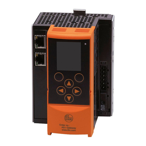
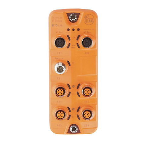
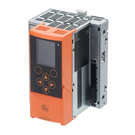
IFM AC1401/02 Application guide

Device Manual Supplement
AS-i Gateway AC14
AC1401/02, AC1411/12, AC1421/22
SmartPLC DataLine AC14
AC1403/04, AC1423/24, AC1433/34
SmartPLC SafeLine AC4S
AC402S, AC412S, AC422S, AC432S
Acyclic command records
Command interface
English
7391129_00_UK 2017 / 09

2
ifm Device Manual Supplement: Acyclic data records and Command interface (AC14 and AC4S) 2017 / 09
Content
Contents
1Preliminary note 4
1.1 Legal and copyright information...........................................................................................5
1.2 Purpose of the document.....................................................................................................5
1.3 Symbols and styles used .....................................................................................................6
1.4 Modification history ..............................................................................................................6
2Safety instructions 7
2.1 General ................................................................................................................................8
2.2 Required background knowledge ........................................................................................8
2.3 Warnings used.....................................................................................................................8
3Acyclic data records 9
3.1 Overview: Acyclic data records (DSx)................................................................................10
3.2 DS1 –System information .................................................................................................11
3.3 DS2 –Digital inputs of the slaves and master flags ..........................................................12
3.3.1 AS-i master status flags..............................................................................................................13
3.3.2 Execution control flags ...............................................................................................................14
3.3.3 Host flags ...................................................................................................................................16
3.3.4 DAE/EE flags..............................................................................................................................16
3.4 DS3 –Analogue inputs of slaves 1(A)...15(B)...................................................................17
3.4.1 Details of the 5-word areas.........................................................................................................18
3.5 DS4 –Analogue inputs of slaves 16(A)...31(B) .................................................................19
3.5.1 Details of the 5-word areas.........................................................................................................20
3.6 DS5 –Digital outputs of the slaves....................................................................................21
3.7 DS6 –Analogue outputs of slaves 1(A)...15(B).................................................................22
3.7.1 Details 4 channels per analogue slave.......................................................................................22
3.8 DS7 –Analogue outputs of slaves 16(A)...31(B)...............................................................23
3.8.1 Details 4 channels per analogue slave.......................................................................................23
3.9 DS8 –Status flags of analogue output data of the slaves 1...31.......................................24
3.10 DS9 –Slave lists LAS, LDS, LPF, LCE .............................................................................25
3.10.1 Details of the slave lists..............................................................................................................25
3.11 DS10 –Slave list LPS........................................................................................................26
3.11.1 Details of the slave lists..............................................................................................................26
3.12 DS11 –Actual configuration data (CDI).............................................................................27
3.13 DS12 –Projected configuration data (PCD)......................................................................28
3.14 DS13 –Image of the input parameters of the slaves (PI)..................................................29
3.15 DS14 –Image of the output parameters of the slaves (PP)..............................................30
3.16 DS15 –Slave error counter, configuration error counter, AS-i cycle counter....................31
3.17 DS17 –AS-i master: Error lists LCEMS, LCEAS, LDAE...................................................32
3.18 DS18 –Fieldbus information..............................................................................................33
4Command channels 36
4.1 Principle of the command channels...................................................................................37
4.1.1 Command status ........................................................................................................................37
4.2 System commands ............................................................................................................38
4.2.1 Overview: System commands....................................................................................................39
4.2.2 Command 0x0101 –Quick setup AS-i master 1 + 2...................................................................40
4.2.3 Command 0x0103 –Select user language.................................................................................42
4.2.4 Command 0x0104 –Change display settings............................................................................44
4.2.5 Command 0x0105 –Set output control......................................................................................45
4.2.6 Command 0x0106 –Set standard PLC operating mode............................................................46

3
ifm Device Manual Supplement: Acyclic data records and Command interface (AC14 and AC4S) 2017 / 09
Content
4.2.7 Command 0x0109 –Set date/time.............................................................................................47
4.2.8 Command 0x010A –Set parameters of the NTP server............................................................49
4.2.9 Command 0x010B –Read date / time / NTP settings................................................................51
4.2.10 Command 0x010C –Reboot system..........................................................................................52
4.2.11 Command 0x010D –Read fieldbus info.....................................................................................53
4.2.12 Command 0x010F –Read message text of an OSC entry ........................................................54
4.2.13 Command 0x0110 –Display target visualisation........................................................................56
4.3 AS-i master commands......................................................................................................57
4.3.1 Overview: AS-i master commands.............................................................................................58
4.3.2 Error codes of the AS-i master commands.................................................................................60
4.3.3 Command 0x0001 –Change parameters of an AS-i slave ........................................................63
4.3.4 Command 0x0003 –Project the currrent AS-i network ..............................................................65
4.3.5 Command 0x0004 –Change LPS..............................................................................................66
4.3.6 Command 0x0005 –Change the operating mode of the AS-i master........................................67
4.3.7 Command 0x0006 –Change AS-i slave address.......................................................................68
4.3.8 Command 0x0007 –Set the auto address mode of the AS-i master..........................................70
4.3.9 Command 0x0009 –Change extended ID1 in the AS-i slave.....................................................71
4.3.10 Command 0x000A –Change PCD.............................................................................................73
4.3.11 Command 0x000D –AS-i master supply voltage, symmetry, earth fault....................................74
4.3.12 Command 0x0015 –Read ID string of an AS-i profile (S-7.4)....................................................76
4.3.13 Command 0x001A –Read AS-i master info...............................................................................79
4.3.14 Command 0x001C –Deactivate slave reset when changing to the protected mode..................80
4.3.15 Command 0x0021 –Read diagnosis string of an AS-i slave (S-7.4)..........................................81
4.3.16 Command 0x0022 –Read parameter string of an AS-i slave (S-7.4).........................................83
4.3.17 Command 0x0023 –Write parameter string of an AS-i slave (S-7.4).........................................85
4.3.18 Command 0x0024 –CTT2 Standard..........................................................................................87
4.3.19 Command 0x0025 –CTT2 standard write..................................................................................89
4.3.20 Command 0x0026 –CTT2 Vendor Specific Read......................................................................91
4.3.21 Command 0x0027 –CTT2 Vendor Specific Write......................................................................93
4.3.22 Command 0x0040 –CTT2 device group read............................................................................95
4.3.23 Command 0x0041 –CTT2 Device Group Write.........................................................................97
4.3.24 Command 0x0042 –CTT2 Vendor Specific Selective Read From Buffer..................................99
4.3.25 Command 0x0043 –CTT2 Vendor Specific Selective Write From Buffer.................................101
4.3.26 Command 0x0044 –CTT2 Vendor Specific Selective Read....................................................103
4.3.27 Command 0x0045 –CTT2 Vendor Specific Selective Write ....................................................105
4.3.28 Command 0x0046 –CTT2 device group selective Rread........................................................107
4.3.29 Command 0x0047 –CTT2 Device Group Selective Write .......................................................109
4.3.30 Command 0x0049 –CTT2 Vendor Specific Exchange ............................................................111
4.3.31 Command 0x004A –CTT2 Device Group Exchange...............................................................113
4.3.32 Command 0x004B –CTT2 Device Group Selective Read From Buffer...................................115
4.3.33 Command 0x004C –CTT2 Device Group Selective Write From Buffer...................................117
4.3.34 Command 0x0050 –Adjust AS-i master settings.....................................................................119
4.3.35 Command 0x0051 –Reset error counter .................................................................................120
5Index 121
6ifm weltweit • ifm worldwide • ifm à l’échelle internationale 123

4
ifm Device Manual Supplement: Acyclic data records and Command interface (AC14 and AC4S) 2017 / 09
Preliminary note
1Preliminary note
Legal and copyright information ...............................................................................................................5
Purpose of the document .........................................................................................................................5
Symbols and styles used..........................................................................................................................6
Modification history...................................................................................................................................6
14801

5
ifm Device Manual Supplement: Acyclic data records and Command interface (AC14 and AC4S) 2017 / 09
Preliminary note
>
1.1 Legal and copyright information
1631
© All rights reserved by ifm electronic gmbh. No part of this manual may be reproduced and used
without the consent of ifm electronic gmbh.
All product names, pictures, companies or other brands used on our pages are the property of the respective rights owners:
AS-i is the property of the AS-International Association, (→www.as-interface.net)
CAN is the property of the CiA (CAN in Automation e.V.), Germany (→www.can-cia.org)
CODESYS™ is the property of the 3S – Smart Software Solutions GmbH, Germany (→www.codesys.com)
DeviceNet™ is the property of the ODVA™ (Open DeviceNet Vendor Association), USA (→ www.odva.org)
EtherNet/IP® is the property of the →ODVA™
EtherCAT®is a registered trade mark and patented technology, licensed by Beckhoff Automation GmbH, Germany
IO-Link®(→www.io-link.com) is the property of the →PROFIBUS Nutzerorganisation e.V., Germany
ISOBUS is the property of the AEF –Agricultural Industry Electronics Foundation e.V., Deutschland
(→www.aef-online.org)
Microsoft®is the property of the Microsoft Corporation, USA (→www.microsoft.com)
PROFIBUS®is the property of the PROFIBUS Nutzerorganisation e.V., Germany (→www.profibus.com)
PROFINET®is the property of the →PROFIBUS Nutzerorganisation e.V., Germany
Windows®is the property of the →Microsoft Corporation, USA
>
1.2 Purpose of the document
23708
This document describes the acyclic data records and the command interface of the following devices:
AS-i Gateway with Profinet device interface (AC1401/AC1402)
AS-i Gateway with Profibus slave interface (AC1411/AC1412)
AS-i Gateway with EtherNet/IP device interace (AC1421/AC1422)
SmartSPS DataLine with Profinet device interface (AC1403/AC1404)
SmartSPS DataLine with EtherNet/IP device interace (AC1423/AC1424)
SmartSPS DataLine with EtherCAT slave interface (AC1433/AC1434)
SmartSPS SafeLine mit Profinet device interface (AC402S)
SmartSPS SafeLine mit Profibus slave interface (AC412S)
SmartSPS SafeLine mit EtherNet/IP device interface (AC422S)
SmartSPS SafeLine mit EtherCAT slave interface (AC432S)
It is part of the device and contains information about the correct handling of the product.
►Read this document before using the device.
►Keep this document during the service life of the device.

6
ifm Device Manual Supplement: Acyclic data records and Command interface (AC14 and AC4S) 2017 / 09
Preliminary note
>
1.3 Symbols and styles used
13839
►...
Instructions
>...
Reaction, result
→...
Cross-reference or internet link
123
0x123
0b010
Decimal number
Hexadecimal number
Binary number
[...]
Designation of pushbuttons, buttons or indications
>
1.4 Modification history
21676
Version
Topic
Date
00
New creation of document
2017 / 09

7
ifm Device Manual Supplement: Acyclic data records and Command interface (AC14 and AC4S) 2017 / 09
Safety instructions
2Safety instructions
General.....................................................................................................................................................8
Required background knowledge.............................................................................................................8
Warnings used..........................................................................................................................................8
213

8
ifm Device Manual Supplement: Acyclic data records and Command interface (AC14 and AC4S) 2017 / 09
Safety instructions
>
2.1 General
22068
The plant manufacturer is responsible for the safety of the plant in which the device is
installed.
If the device is used in a way that is not intended by the manufacturer, the protection
supported by the device may be impaired.
Non-observance of the instructions, operation which is not in accordance with use as
prescribed below, wrong installation or incorrect handling can affect the safety of operators
and machinery.
►Observe these operating instructions.
►Adhere to the warning notes on the product.
>
2.2 Required background knowledge
22046
This document is intended for specialists. Specialists are people who, based on their relevant training
and experience, are capable of identifying risks and avoiding potential hazards that may be caused
during operation or maintenance of the product.
The document contains information about the correct handling of the product.
>
2.3 Warnings used
13685
WARNING
Death or serious irreversible injuries may result.
CAUTION
Slight reversible injuries may result.
NOTICE
Property damage is to be expected or may result.
Important note
Non-compliance may result in malfunction or interference.
Information
Supplementary note.

9
ifm Device Manual Supplement: Acyclic data records and Command interface (AC14 and AC4S) 2017 / 09
Acyclic data records
3Acyclic data records
Overview: Acyclic data records (DSx)....................................................................................................10
DS1 –System information......................................................................................................................11
DS2 –Digital inputs of the slaves and master flags...............................................................................12
DS3 –Analogue inputs of slaves 1(A)...15(B)........................................................................................17
DS4 –Analogue inputs of slaves 16(A)...31(B)......................................................................................19
DS5 –Digital outputs of the slaves ........................................................................................................21
DS6 –Analogue outputs of slaves 1(A)...15(B)......................................................................................22
DS7 –Analogue outputs of slaves 16(A)...31(B)....................................................................................23
DS8 –Status flags of analogue output data of the slaves 1...31 ...........................................................24
DS9 –Slave lists LAS, LDS, LPF, LCE..................................................................................................25
DS10 –Slave list LPS..........................................................................................................................26
DS11 –Actual configuration data (CDI) .................................................................................................27
DS12 –Projected configuration data (PCD)...........................................................................................28
DS13 –Image of the input parameters of the slaves (PI) ......................................................................29
DS14 –Image of the output parameters of the slaves (PP)...................................................................30
DS15 –Slave error counter, configuration error counter, AS-i cycle counter........................................31
DS17 –AS-i master: Error lists LCEMS, LCEAS, LDAE........................................................................32
DS18 –Fieldbus information..................................................................................................................33
17036
The data records are transmitted acyclically upon request of the <fieldbus> master.

10
ifm Device Manual Supplement: Acyclic data records and Command interface (AC14 and AC4S) 2017 / 09
Acyclic data records
>
3.1 Overview: Acyclic data records (DSx)
23386
Data
record
Content
Access
r = read
w = write
Words
DS1
System information
r
26
DS2
Digital inputs of slaves 1(A)…31(A) and 1B…31B and master flags
(Status AS-i master and exec.-ctl. flags and host flags)
r
36
DS3
Analogue inputs of slaves 1(A)…15(B)
r
75
DS4
Analogue inputs of slaves 16(A)…31(B)
r
80
DS5
Digitale outputs of slaves 1(A)…31(A) and 1B...31B
r/w
32
DS6
Analogue outputs of slaves 1(A)…15(B)
r/w
60
DS7
Analogue otputs of slaves 16(A)…31(B)
r/w
64
DS8
Statusflags of analogue output data of slaves 1(A)…31(A) and 1B…31B
r
32
DS9
Slave lists LAS, LDS, LPF, LCE
r
16
DS10
Slave list LPS
r
4
DS11
Actual Configuration data (CDI)
r
64
DS12
Projected Configuration data (PCD)
r
64
DS13
Image of input parameter
r
32
DS14
Image of output parameter
r/w
32
DS15
Slave error counter, configuration error counter, AS-i cycle counter
r
72
DS16
n.a.
–
–
DS17
AS-i master: Error lists LCEMS, LCEAS, LDAE
r
12
DS18
Fieldbus information (only available via CODESYS)
r
19

11
ifm Device Manual Supplement: Acyclic data records and Command interface (AC14 and AC4S) 2017 / 09
Acyclic data records
>
3.2 DS1 –System information
8753
Offset
Word no.
Bit
15
14
13
12
11
10
9
8
7
6
5
4
3
2
1
0
0
Article number 1) (byte 0) = "A"
Article number 1) (byte 1) = “C"
1
Article number 1) (byte 2) = A1
Article number 1) (byte 3) = A2
2
Article number 1) (byte 4) = A3
Article number 1) (byte 5) = A4
3
Device number 2) (byte 1) = G1
Device number 2) (byte 0) = G2
4
Serial number 3) (byte 0, MSB)
Serial number 3) (byte 1)
5
Serial number 3) (byte 2)
Serial number 3) (byte 3)
6
Serial number 3) (byte 4)
Serial number 3) (byte 5)
7
Serial number 3) (byte 6)
Serial number 3) (byte 7)
8
Serial number 3) (byte 8)
Serial number 3) (byte 9)
9
Serial number 3) (byte 10)
Serial number 3) (byte 11)
10
Software type
Software Version (Major Version)
11
Software Version (Minor Version)
Software Version (Build Version)
12
Operating hours 5) Total (byte 3, high byte)
Operating hours 5) Total (byte 2)
13
Operating hours 5) Total (byte 1)
Operating hours 5) Total (byte 0, low byte)
14
Operating hours 5) Uptime (byte 3, high byte)
Operating hours 5) Uptime (byte 2)
15
Operating hours 5) Uptime (byte 1)
Operating hours 5) Uptime (byte 0, low byte)
16
Operating hours 5) standard PLC (byte 3, high byte)
Operating hours 5) standard PLC (byte 2)
17
Operating hours 5) standard PLC (byte 1)
Operating hours 5) standard PLC (byte 0, low byte)
18
Operating hours 5) display (byte 3, high byte)
Operating hours 5) display (byte 2)
19
Operating hours 5) display (byte 1)
Operating hours 5) display (byte 0, low byte)
20
Device temperature 6) (byte 0, high byte)
Device temperature 6) (byte 1, low byte)
21
reserved
Number of AS-i masters
22
Language 7) (1st letter)
Language 7) (2nd letter)
23
Return to start screen (on/off)
Screen saver (on/off)
24
CODESYS standard PLC operating mode (activ/inactiv)
Output access
25
Device cycle in µs (high byte)
Device cycle in µs (low byte)
1) Article number: "AC" + A1+ A2+ A3+ A4as character string, e.g. "AC14 and AC4S"
2) Device number: G1+ G2as character string, e.g. "AB"
3) Serial number: 12-digit character string
5) Operating hours: in seconds, Unsigned Double word (32 bit), e.g. 0x000010A709F = 108447 seconds
6) Device temperature: in 1/100 °C, signed Word (16 bit), e.g. 4232 = 42.32 °C
7) Language: LANG_ID as ASCII code, e.g. "DE" = "D" + "E" = 0x44 + 0x45
6) Device temperature: in 1/100 °C, signed Word (16 bit), e.g. 4232 = 42.32 °C
7) Language: LANG_ID as ASCII code, e.g. "DE" = "D" + "E" = 0x44 + 0x45

12
ifm Device Manual Supplement: Acyclic data records and Command interface (AC14 and AC4S) 2017 / 09
Acyclic data records
>
3.3 DS2 –Digital inputs of the slaves and master flags
8754
Offset
Word no.
Bit
15
14
13
12
11
10
9
8
7
6
5
4
3
2
1
0
0
reserved
Slave 1(A): D3...D0
reserved
reserved
1
reserved
Slave 3(A): D3...D0
reserved
Slave 2(A): D3...D0
2
reserved
Slave 5(A): D3...D0
reserved
Slave 4(A): D3...D0
...
...
...
...
...
14
reserved
Slave 29(A): D3...D0
reserved
Slave 28(A): D3...D0
15
reserved
Slave 31(A): D3...D0
reserved
Slave 30(A): D3...D0
16
reserved
Slave 1B: D3...D0
reserved
reserved
17
reserved
Slave 3B: D3...D0
reserved
Slave 2B: D3...D0
...
...
...
...
30
reserved
Slave 29B: D3...D0
reserved
Slave 28B: D3...D0
31
reserved
Slave 31B: D3...D0
reserved
Slave 30B: D3...D0
32
AS-i master status flags (→AS-i master status flags (→p. 13))
33
Execution control flags (→Execution control flags (→p. 14))
34
Host flags (→Host flags (→p. 16))
35
DAE / EE-Flags (→DAE/EE flags (→p. 16))

13
ifm Device Manual Supplement: Acyclic data records and Command interface (AC14 and AC4S) 2017 / 09
Acyclic data records
>
3.3.1 AS-i master status flags
7160
The AS-i master status flags provide information about the status of the AS-i master. After a status
change, the AS-i master immediately updates the flags.
The AS-i master status flags are saved in the following register:
AS-i master status flags
15
14
13
12
11
10
9
8
7
6
5
4
3
2
1
0
ECPS
ECP
–
–
WCD
CM
–
HWDT
SER
HER
Legend:
Flag
Designation
Description
Initial value at power-on
HER
Hardware Error
1 (TRUE):
a hardware error occurred during the power-on
self test
0 (FALSE)
SER
Software Error
1 (TRUE):
Software error occurred:
Stack Overflow, Stack Underflow, Undefined
Opcode, Instruction Fault, Illegal Access,
Watchdog Timeout
0 (FALSE)
HWDT
Host Watchdog
Timeout
1 (TRUE):
Host watchdog not triggered by the host within
200 ms; master changed to the offline mode
0 (FALSE)
CM
Configuration Missing
1 (TRUE):
Configuration not yet fully received from the host.
Becomes FALSE as soon as PCD, PP and LPS
have been set
1 (TRUE)
WCD
Watchdog Control
Disabled
1 (TRUE):
Signals the host that the watchdog signal is not
processed in the master.
0 (FALSE)
ECP
Execution Control
Phase
Display of the different phases the execution control goes
through during boot (→table).
0
ECPS
Execution Control
Phase State
Display of the substates of the different execution control
phases (→table).
0
Execution Control Phase
Execution Control Phase State
0 = inactive
–
1 = start phase
0 = master start and initialisation
1 = wait for configuration
2 = wait for start
2 = reserved
–
3 = offline phase
–
4 = detection phase
–
5 = activation phase
–
6 = normal operation
0 = normal data exchange
1 = slave finder activated

14
ifm Device Manual Supplement: Acyclic data records and Command interface (AC14 and AC4S) 2017 / 09
Acyclic data records
>
3.3.2 Execution control flags
7161
The execution control flags provide information about the execution control of the AS-i master. The
flags are updated by the AS-i master immediately after each change.
The execution control flags are saved in the following register:
Execution control flags
15
14
13
12
11
10
9
8
7
6
5
4
3
2
1
0
–
NOPF
CCOK
PE
–
DEA
AAE
POK
OR
APF
NOA
CA
AA
AN
S0
COK
Legend:
Flag
Designation
Description
Initial value at power-on
COK
Config_OK
1 (TRUE):
The configuration of all AS-i slaves on the
network corresponds to the projection
data (CDI=PCD for all activated slaves)
&& (LDS=LPS=LAS)
Exception:
Flag APF = 1 and LPS = empty, then
COK = 1
0 (FALSE)
S0
LDS.0
1 (TRUE):
Slave with address 0 found
0 (FALSE)
AN
Auto_Address_Assign
1 (TRUE):
Auto addressing possible
(protected mode = active && auto
addressing = active && PCD = CDI &&
LDS <=LPS)
0 (FALSE)
AA
Auto_Address_Available
1 (TRUE):
All the necessary conditions for auto
addressing are fulfilled. The master waits
for slave 0.
0 (FALSE)
CA
Configuration_Active
0 (FALSE):
1 (TRUE):
Master in protected mode
Master in projection mode
0 (FALSE)
NOA
Normal_Operation_Active
1 (TRUE):
Master is in the normal mode
(The AS-i master has communicated with
at least one slave since the last offline
phase. Even if the slave disappears after
this, the signal will remain set.)
0 (FALSE)
APF
Asi_Power_Fail
0 (FALSE):
1 (TRUE):
AS-i voltage OK
AS-i voltage too low
1 (TRUE)
OR
Offline_Ready
1 (TRUE):
Master has gone through the offline
phase and waits for:
APF = 0 and a timeout of 1s
0 (FALSE)
POK
Periphery_OK
1 (TRUE):
No peripheral faults present, all bits of
LPF = 0.
0 (FALSE)
AAE
Auto_Address_Enable
1 (TRUE):
Auto addressing switched on
(Echo of Set_Auto_Address_Enable of
host)
0 (FALSE)
DEA
Data_Exchange_Active
1 (TRUE):
Data exchange between master and
slaves activated (reflects DEA of host
flags)
1 (TRUE)
0 (FALSE):
Instead of the data exchange, ReadID is
continually executed on the slaves.
PE
Protocol Error
1 (TRUE):
0 (FALSE):
CTT protocol error
No CTT protocol error
0 (FALSE)

15
ifm Device Manual Supplement: Acyclic data records and Command interface (AC14 and AC4S) 2017 / 09
Acyclic data records
Flag
Designation
Description
Initial value at power-on
CCOK
CTT_Config_OK
1 (TRUE):
The configuration of all CTT slaves on the
network corresponds to the projected
CCT data.
(CCDI = PCCD for all CTT slaves)
0 (FALSE)
NOPF
No_Offline_Phase_Flag
1 (TRUE):
The master skips the offline phase if one
of the following actions is performed:
–change to protected mode
–change of PCD
–change of LPS
–change of PCCD
0 (FALSE)
0 (FALSE):
The master goes through the offline
phase when changing to the protected
mode the next time.

16
ifm Device Manual Supplement: Acyclic data records and Command interface (AC14 and AC4S) 2017 / 09
Acyclic data records
>
3.3.3 Host flags
7162
The host flags are regularly updated by the host. The AS-i master cyclically checks the host flags for
changes.
The host flags are saved in the following register:
Host Flags
15
14
13
12
11
10
9
8
7
6
5
4
3
2
1
0
–
–
–
–
–
–
–
–
–
–
–
–
–
–
DEA
OFF
Legend:
Flag
Designation
Description
Initial value at power-on
OFF
Offline
1 (TRUE):
Execution control of the master changes to the
offline mode. The function Set_Offline_Mode()
is implemented via this flag.
0 (FALSE)
DEA
Data_Exchange_Active
1 (TRUE):
Data exchange activated between master and
slaves. The function
Set_Data_Exchange_Active() is implemented
via this flag
1 (TRUE)
>
3.3.4 DAE/EE flags
16935
The DAE/EE flags indicate if the double address detection and the earth fault detection are on.
The DEA/EE flags are saved in the following register:
DAE/EE flags
15
14
13
12
11
10
9
8
7
6
5
4
3
2
1
0
--
--
--
--
--
--
--
DAE
active
--
--
--
--
--
--
--
EE
active
Legend:
Flag
Designation
Description
Initial value at PowerOn
DAE
active
Double address
detection active
1 (TRUE):
0 (FALSE):
Double address detection is on.
Double address detection is off.
0 (FALSE)
EE active
Earth fault detection is
active
1 (TRUE):
0 (FALSE):
Earth fault detection is on.
Earth fault detection is off.
1 (TRUE)

17
ifm Device Manual Supplement: Acyclic data records and Command interface (AC14 and AC4S) 2017 / 09
Acyclic data records
>
3.4 DS3 –Analogue inputs of slaves 1(A)...15(B)
8756
Offset
Word no.
Bit
15
14
13
12
11
10
9
8
7
6
5
4
3
2
1
0
0...4
Analogue input data of single slave 1 or of (slave 1A and slave 1B)
5...9
Analogue input data of single slave 2 or of (slave 2A and slave 2B)
10...14
Analogue input data of single slave 3 or of (slave 3A and slave 3B)
15...19
Analogue input data of single slave 4 or of (slave 4A and slave 4B)
20...24
Analogue input data of single slave 5 or of (slave 5A and slave 5B)
25...29
Analogue input data of single slave 6 or of (slave 6A and slave 6B)
30...34
Analogue input data of single slave 7 or of (slave 7A and slave 7B)
35...39
Analogue input data of single slave 8 or of (slave 8A and slave 8B)
40...44
Analogue input data of single slave 9 or of (slave 9A and slave 9B)
45...49
Analogue input data of single slave 10 or of (slave 10A and slave 10B)
50...54
Analogue input data of single slave 11 or of (slave 11A and slave 11B)
55...59
Analogue input data of single slave 12 or of (slave 12A and slave 12B)
60...64
Analogue input data of single slave 13 or of (slave 13A and slave 13B)
65...69
Analogue input data of single slave 14 or of (slave 14A and slave 14B)
70...74
Analogue input data of single slave 15 or of (slave 15A and slave 15B)

18
ifm Device Manual Supplement: Acyclic data records and Command interface (AC14 and AC4S) 2017 / 09
Acyclic data records
>
3.4.1 Details of the 5-word areas
8758
Offset
Word no.
Bit
15
14
13
12
11
10
9
8
7
6
5
4
3
2
1
0
n
Analogue value channel 0 of single slave x or channel 0 of slave xA
n+1
Analogue value channel 1 of single slave x or channel 1 of slave xA
n+2
Analogue value channel 2 of single slave x or channel 0 of slave xB
n+3
Analogue value channel 3 of single slave x or channel 1 of slave xB
n+4
TIB
--
TIA
--
TOB
--
TOA
--
O3
V3
O2
V2
O1
V1
O0
V0
Legend:
On
overflow bit
1 bit
0 = data is in the valid range
1 = data is in the invalid range (especially in case of input modules when
the measuring range is not reached or exceeded)
TIx
transfer to the slave
(transfer Input)
1 bit
from master profile M4 onwards:
0 = slave transmits input data as a value
(15 bits long, plus sign)
1 = slave transmits input data as a bit pattern
(16 bits long, no sign)
TOx
transfer from the slave
(transfer output)
1 bit
from master profile M4 onwards:
0 = slave receives output data as a value
(15 bits long, plus sign)
1 = slave receives output data as a bit pattern
(16 bits long, no sign)
Vn
valid bit
1 bit
0 = values in channel n are invalid
1 = values in channel n are valid
Output data must be valid (Vn = 1) to be enabled in the AS-i slave!

19
ifm Device Manual Supplement: Acyclic data records and Command interface (AC14 and AC4S) 2017 / 09
Acyclic data records
>
3.5 DS4 –Analogue inputs of slaves 16(A)...31(B)
8759
Offset
Word no.
Bit
15
14
13
12
11
10
9
8
7
6
5
4
3
2
1
0
0...4
Analogue input data of single slave 16 or of (slave 16A and slave 16B)
5...9
Analogue input data of single slave 17 or of (slave 17A and slave 17B)
10...14
Analogue input data of single slave 18 or of (slave 18A and slave 18B)
15...19
Analogue input data of single slave 19 or of (slave 19A and slave 19B)
20...24
Analogue input data of single slave 20 or of (slave 20A and slave 20B)
25...29
Analogue input data of single slave 21 or of (slave 21A and slave 21B)
30...34
Analogue input data of single slave 22 or of (slave 22A and slave 22B)
35...39
Analogue input data of single slave 23 or of (slave 23A and slave 23B)
40...44
Analogue input data of single slave 24 or of (slave 24A and slave 24B)
45...49
Analogue input data of single slave 25 or of (slave 25A and slave 25B)
50...54
Analogue input data of single slave 26 or of (slave 26A and slave 26B)
55...59
Analogue input data of single slave 27 or of (slave 27A and slave 27B)
60...64
Analogue input data of single slave 28 or of (slave 28A and slave 28B)
65...69
Analogue input data of single slave 29 or of (slave 29A and slave 29B)
70...74
Analogue input data of single slave 30 or of (slave 30A and slave 30B)
75...79
Analogue input data of single slave 31 or of (slave 31A and slave 31B)

20
ifm Device Manual Supplement: Acyclic data records and Command interface (AC14 and AC4S) 2017 / 09
Acyclic data records
>
3.5.1 Details of the 5-word areas
8758
Offset
Word no.
Bit
15
14
13
12
11
10
9
8
7
6
5
4
3
2
1
0
n
Analogue value channel 0 of single slave x or channel 0 of slave xA
n+1
Analogue value channel 1 of single slave x or channel 1 of slave xA
n+2
Analogue value channel 2 of single slave x or channel 0 of slave xB
n+3
Analogue value channel 3 of single slave x or channel 1 of slave xB
n+4
TIB
--
TIA
--
TOB
--
TOA
--
O3
V3
O2
V2
O1
V1
O0
V0
Legend:
On
overflow bit
1 bit
0 = data is in the valid range
1 = data is in the invalid range (especially in case of input modules when
the measuring range is not reached or exceeded)
TIx
transfer to the slave
(transfer Input)
1 bit
from master profile M4 onwards:
0 = slave transmits input data as a value
(15 bits long, plus sign)
1 = slave transmits input data as a bit pattern
(16 bits long, no sign)
TOx
transfer from the slave
(transfer output)
1 bit
from master profile M4 onwards:
0 = slave receives output data as a value
(15 bits long, plus sign)
1 = slave receives output data as a bit pattern
(16 bits long, no sign)
Vn
valid bit
1 bit
0 = values in channel n are invalid
1 = values in channel n are valid
Output data must be valid (Vn = 1) to be enabled in the AS-i slave!
This manual suits for next models
9
Table of contents
Other IFM Gateway manuals
Popular Gateway manuals by other brands

Vimar
Vimar NEVE UP 09597 manual

Agilent Technologies
Agilent Technologies Agilent E5810A Getting started

WTE
WTE MReX-SatLink user manual

ZyXEL Communications
ZyXEL Communications AMG1302-T11C quick start guide

NCM
NCM NCMO-5G4W10CW manual

Thermokon
Thermokon SRC-KNX/ENO Operating and installation instructions