18 19
Failure to observe these instructions could re-
sult in damage to the decomposition vessel.
Exploding decomposition vessels present a risk
of serious injury or death. When working with
unknown substances, select very small weighted
samples at the start in order to determine the na-
tural energy.
Normally solid materials in powder form can be
combusted directly. Materials which com-
bust quickly (e.g. benzoic acid) must not
be burnt loose. These materials tend to splash
and there is therefore no guarantee of complete
combustion.
Furthermore, this can damage the inner
wall of the decomposition vessel.
IKA pelleting press C 21 and IKA analytical mill A
11 basic (see Accessories) are available for sample
preparation.
Materials which are dicult to burn (materials
with a high mineral content, low caloric materi-
als) can often only be fully combusted using IKA
acetobutyrate capsules C 10, IKA combustion
bags C 12 or IKA combustible crucible C 14 (see
Accessories). It is also possible to use liquid bur-
ning aids such as paran oil.
Before filling the capsule or the combustion bag
with the substance to be determined, weigh
them to calculate the extra external energy ad-
ded by the burning aid from the weight and the
calorific value. This must be taken into account
in QExternal2. You should keep the amount of
burning aid used to a minimum.
Most fluid substances can weighed out directly
into the crucible. Highly volatile substances are
poured into combustion capsules (IKA gelatine
capsules C 9 or IKA acetobutyrate capsules C 10,
see Accessories) and combusted together with
the capsules.
The burning aids (e.g. cotton thread) must also
fully combust. If there is any unburnt residue, the
test must be repeated.
When working with unknown substances, select
very small weighted samples at the start in order
to determine the natural energy. If you are bur-
ning unknown samples, leave the room or keep
your distance from the calorimeter.
After combustion the water produced is collec-
ted and the decomposition vessel is thoroughly
rinsed with distilled water. The water used for
rinsing and the solution produced are combined
and examined for their acidity. If the sulphur con-
tent of the fuel and the nitric acid correction are
known, it is not necessary to analyse the water.
Note: in all the automatic calculations an extra
100 J have already been included for the electric
ignition energy. This value cannot be set.
Materials which are dicult to ignite or combust
are combusted together with a burning aid. The
burning aid is first weighed and then put into
the crucible with the sample. The additional heat
quantity can be determined from the weight of
the burning aid and its known specific calorific
value. You must correct the test result by this heat
quantity.
IKA- combustible crucible C 14 is a combustible
crucible, which can be used instead of a standard
crucible. The combustible crucible burns without
leaving any residue whatsoever. When using a
combustible crucible you do not need an extra
cotton thread. The crucible is placed directly on
the permanent ignition wire in the decompositi-
on vessel and ignited.
The cleanliness of the material used in the com-
bustible crucible prevents chemical contaminati-
on of the sample (no blank values).
Decomposition vessels, in which the combustible
crucible is used, must be fitted with an extra part
(support C 5010.4, see Accessories). The sample
is weighed out into the combustible crucible as
normal. In most cases no additional burning aid
is required because the combustible crucible itself
serves as a burning aid.
Virtually all of the materials to be studied contain
sulphur and nitrogen. Under the conditions in ca-
lorimetric measurements, sulphur and nitrogen
combust to SO2, SO3 and NOx. Together with
the water from combustion and moisture, sulp-
huric and nitric acid as well as heat of solution
are produced. In order to obtain the standard ca-
lorific value, the influence of the heat of solution
on the calorific value is corrected. The calculation
formulae depend on the standard used. These
are not taken into account in the calculation for
C 200. Use IKA's CalWin software for this.
5.3 Information about the sample
FIt is essential that the sample fully combusts
to ensure correct determination of the calorific
value. After each experiment check the crucible
and all the solid residue for signs of incomplete
combustion.
As a rule the weighted sample must be se-
lected in such a way that the temperature
increase during the measurement is below 4 K
and comes close to the temperature increase
of the calibration (max. extra energy: 40,000 J).
The system must be calibrated in every work
mode used.
If a calorimeter is operated with several de-
composition vessels, you will need to deter-
mine the heat capacity of the system for each
decomposition vessel.
Ensure that calibration is carried out under the
same conditions as the subsequent tests. If sub-
stances are used in the decomposition vessel in
combustion tests (e.g. distilled water or solu-
tions), you must use exactly the same amount of
this substance for calibration.
For more detailed information on calibration, ple-
ase see the relevant standards.
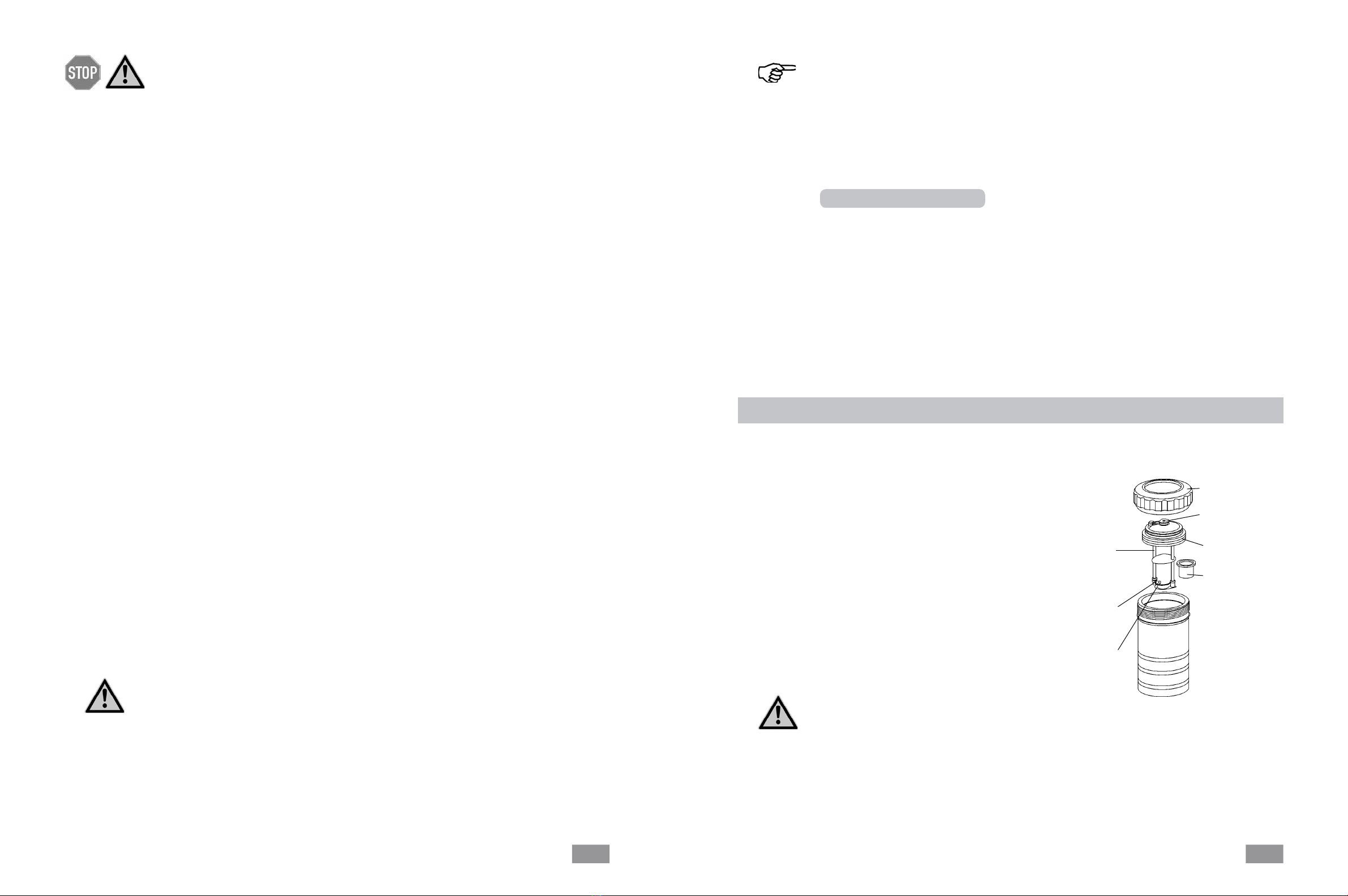
6.1 Decomposition vessel C 5010
If several decomposition vessels are used,
their individual parts must not be interchan-
ged (see Stamping individual parts).
To prolong the life of wearing parts (o-rings,
seals, etc.) we recommend that you always
work with a water trap.
5.4 Calibration
The calorimeter system must be calibrated before
accurate measurements are possible. This is done
by combusting tablets made of certified benzoic
acid (see Accessories) with a known calorific va-
lue. The heat quantity required to raise the tem-
perature of the calorimeter system by one Kelvin
is used to determine the heat capacity of the so-
called "C-value" of the system. For this calculati-
on the formula (1) (see section 5.1) is adapted:
C = (Ho * m + QExt1 + QExt2) / DT (2)
This value is used for determining the following
calorific values.
The heat capacity is determined by the measu-
ring cell and the decomposition vessel. It has a
significant influence on the calorific value to be
calculated and must be redetermined in particular
when using for the first time, after servicing and
when parts are replaced. A monthly control mea-
surement is recommended.
The term "measurements" below refers to both
the measurements to calibrate the calorimeter
system (calibration measurements) and the actual
measurements for determining the calorific value.
The difference lies in the calculation (cf. section
5, formulae (1) and (2)), whereas preparation and
performance are virtually identical.
Exact measurements are only possible when the
individual test steps are carried out carefully.
You must therefore follow the exact proce-
dure described in section 1 "For your safe-
ty” and in the following sections
Please also see section 5 "Calorimetric measure-
ments”.
Failure to observe these instructions could re-
sult in damage to the decomposition vessel.
Damaged decomposition vessels could crack!
Follow the operating instructions for the de-
composition vessel!
Preparing and performing measurements
Union nut
Oxygen valve
Cover
Crucible
Electric
ignition
contact
Ignition
wire
Crucible
holder