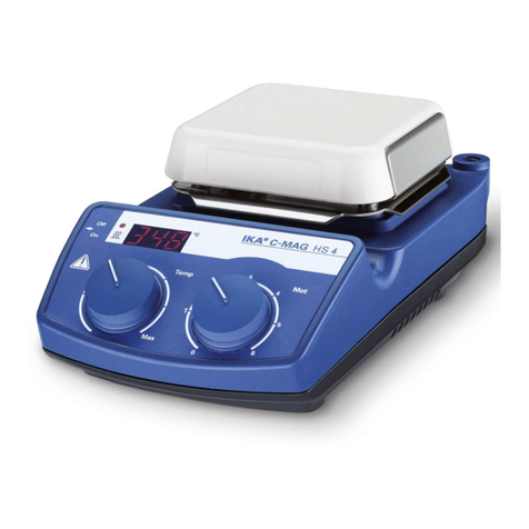
IKA C-MAG HS4 User manual

IKA®C-MAG HS 4 digital
IKA®C-MAG HS 7 digital
IKA®C-MAG HS10 digital
20000005389
CMAG_HS 4_7_10 d_062016
C-MAG HS 7 digital
Betriebsanleitung DE 5
Ursprungssprache
Operating instructions EN 11
Mode d’emploi FR 17
Instruções de operação PT 23
Руководство по эксплуатации
RU 29
使用说明 ZH 35
取扱説明書
JA 41
사용 설명서
KO 47
Indicationes de seguridad ES 53
Veiligheidsinstructies NL 54
Norme di sicurezza IT 56
Säkerhetsanvisningar SV 58
Sikkerhedshenvisninger DA 59
Sikkerhetsanvisninger NO 61
Turvallisuusohjeet FI 62
Wskazówki bezpieczeństwa PL 64
Bezpečnostní pokyny CS 65
Biztonsági utasitások HU 67
Varnostna opozorila SL 68
Bezpečnostné pokyny SK 70
Ohutusjuhised ET 71
Drošības norādes LV 72
Nurodymai dėl saugumo LT 74
Инструкции за безопасност
BG 75
Indicaţii de siguranţă RO 77
Υποδείξείς ασφάλείας EL 78

2
ED
ABC
HGI
F
Fig. 1
J
K
ML
N

3
Pos. 名称 名称 이름
A电源开关 メインスイッチ 메인스위치
B调温旋钮 加熱調整ノブ 온도 조절 다이얼
C调速旋钮 回転数調整ノブ 회전 조절 다이얼
D屏幕窗口 ディスプレイ 디스플레이
E加热指示灯 LED加熱プレートランプ 가열LED디스플레이
F外置温度传感器指示灯 LED外部温度コントローラランプ 온도센서LED디스플레이
G电源接口 電源差込口 전원소켓
H支杆螺孔 H16Vサポートロッド用接続穴 스탠드 연결 나사 홈
IPT 1000温度传感器接口 温度センサー接続ジャック 온도센서 연결 소켓
J操作模式 作動モード 운전 모드
K实际温度 実温度値 실제 열판 온도
L目标温度 設定温度値 온도-설정-값
M加热显示 加熱ランプ 히터 활성화 완료
NHI TEMP 符号 HI TEMP シンボル HITEMP기호
Pos. Bezeichnung Designation Désignation Descriçao конструкции
AGeräteschalter Switch Commutateur Switches Dispositivos Включатель питания
BBedienknopf Rotating knob Bouton rotatif Botão de regulação Маховик регулировки мощности нагрева
CBedienknopf Rotating knob Bouton rotatif Botão de regulação Маховик регулировки скорости вращения
DLCD-Display LCD display Affichage LCD Display LCD
Дисплей
ELED Energiezufuhr LED energy-input
LED alimentation d’énergie
A oferta de energia LED Индикатор активности нагревательной
Heizplatte heating plate plaque chauffante Placa de aquecimento поверхности
FLED Externer
LED external temperature
LED Sonde de tem- LED do sensor de Индикатор внешнего датчика
Temperatursensor sensor pérature externe temperatura externa температуры
GNetzbuchse Mains socket Prise secteur Power jack Разъем кабеля питания
HStativgewindebohrung Threaded support bore Alésage fileté du statif Buraco do tripé com rosca
Резьбовое отверстии для штатива
IAnschluss PT 1000 Connection PT 1000 Connexion du PT 1000 Conectando PT 1000 Cоединительный штепсель
JBetriebsmodus Mode of operation Mode de fonctionnement Modo de operação Режим работы
KIsttemperatur Actual temperature Température effective Temperatura real Фактическая температура
LSolltemperatur Target temperature Température de consigne Temperatura nominal Заданная температура
MEnergiezufuhr Energy-input heating Alimentation d’énergie, A oferta de energia placa Подача энергии на нагревательную
Heizplatte plate plaque chauffante de aquecimento пластину
NHI TEMP Symbol HI TEMP symbol Symbole HI TEMP Ícone de HI TEMP Символ «HI TEMP» («Высокая температура»)

4
Konformitätserklärung DE
Wir erklären in alleiniger Verantwortung, dass dieses Produkt den Bestimmungen der Richtlinien 2014/35/EU, 2014/30/EU und 2011/65/
EU entspricht und mit den folgenden Normen und normative Dokumenten übereinstimmt: EN 61010-1, EN 61010-2-010, EN 61010-2-
051, EN 61326-1, EN 60529 und EN ISO 12100.
Declaration of conformity EN
We declare under our sole responsibility that this product corresponds to the directives 2014/35/EU, 2014/30/EU and 2011/65/EU and
conforms with the following standards or normative documents: EN 61010-1, EN 61010-2-010, EN 61010-2-051, EN 61326-1, EN
60529 and EN ISO 12100.
Déclaration de Conformité FR
Nous déclarons sous notre seule responsabilité que le présent produit est conforme aux prescriptions des directives 2014/35/UE,
2014/30/UE et 2011/65/UE, ainsi qu‘aux normes et documents normatifs suivants: EN 61010-1, EN 61010-2-010, EN 61010-2-051, EN
61326-1, EN 60529 et EN ISO 12100.
Declaração de conformidade PT
Declaramos, sob responsabilidade exclusiva, que este produto cumpre as disposições das diretivas 2014/35/UE, 2014/30/UE e2011/65/UE e
está de acordo com as seguintes normas ou documentos normativos:
EN 61010-1, EN 61010-2-010, EN 61010-2-051, EN 61326-1, EN
60529
e EN ISO 12100.
Сертификат соответствия RU
Мы с полной ответственностью заявляем, что данный продукт соответствует требованиям документов 2014/35/EU, 2014/30/
EU и 2011/65/EU и отвечает стандартам или стандартизованным документам: EN 61010-1, EN 61010-2-010, EN 61010-2-051, EN
61326-1, EN 60529 и EN ISO 12100.

5
Seite
Konformitätserklärung 4
Sicherheitshinweise 5
Auspacken 6
Bestimmungsgemäßer Gebrauch 6
Betriebsmodi einstellen 7
Sicherheitstemperaturbegrenzung 7
HI TEMP einstellen 7
Gewährleistung 7
Inbetriebnahme 8
Fehlercodes 8
Zubehör 9
Montage des Stativstabes 9
Instandhaltung 9
Technische Daten 10
Zu Ihrem Schutz
•Lesen Sie die Betriebsanleitung vor Inbetriebnahme voll-
ständig und beachten Sie die Sicherheitshinweise.
•Bewahren Sie die Betriebsanleitung für Alle zugänglich auf.
•
Beachten Sie, dass nur geschultes Personal mit dem Gerät arbeitet.
•
Beachten Sie die Sicherheitshinweise, Richtlinien, Arbeitsschutz-
und
Unfallverhütungsvorschriften.
•Steckdose muss geerdet sein (Schutzleiterkontakt).
•Achtung - Magnetismus! Beachten Sie die Auswirkungen
des Magnetfeldes (Herzschrittmacher, Datenträger...).
•Verbrennungsgefahr! Vorsicht beim Berühren von Gehäuse-teilen und
Heizplatte. Die Heizplatte kann über 500 °C heiß werden. Beachten Sie
die Restwärme nach dem Ausschalten beachten.
•Stellen Sie sicher, dass das Netzkabel die Heizplatte nicht berührt.
•Tragen Sie Ihre persönliche Schutzausrüstung entsprechend der
Gefahrenklasse des zu bearbeitenden Mediums. Ansonsten be-steht
eine Gefährdung durch:
- Spritzen und Verdampfen von Flüssigkeiten
- Herausschleudern von Teilen
- Freiwerden von toxischen oder brennbaren Gasen
•Stellen Sie das Gerät frei auf einer ebenen, stabilen, sauberen, rutsch-
festen, trockenen und feuerfesten Fläche auf.
•Die Gerätefüße müssen sauber und unbeschädigt sein.
•Stellen Sie vor Inbetriebnahme die Drehknöpfe auf Linksanschlag.
Steigern Sie die Drehzahl langsam.
•Reduzieren Sie die Drehzahl, falls
- Medium infolge zu hoher Drehzahl aus dem Gefäß spritzt
- unruhiger Lauf auftritt
- sich das Gefäß auf der Aufstellplatte bewegt.
•Achtung! Mit diesem Gerät dürfen nur Medien bearbeitet bzw. erhitzt
werden, deren Flammpunkt über der eingestellten Solltemperatur (0 ...
500 °C) liegt.
Die eingestellte Solltemperatur muss immmer mindestens 25 °C unter-
halb des Brennpunktes des verwendeten Mediums liegen.
•Prüfen Sie vor jeder Verwendung Gerät und Zubehör auf Beschä-
digungen. Verwenden Sie keine beschädigten Teile.
•Ersetzen Sie beschädigte Teile nur durch Ersatzteile, die dem Original
in Funktion und Qualität gleich sind.
• Verwenden Sie das Gerät nicht, falls die keramische Aufstellplatte
Beschädigungen z.B. Kratzer, Absplitterungen oder Verätzungen aufweist.
Eine beschädigte Aufstellplatte kann bei Benutzung brechen.
• Beachten Sie eine Gefährdung durch
- entzündliche Materialien.
- Glasbruch
- falsche Dimensionierung des Gefäßes
- zu hohen Füllstand des Mediums
- unsicheren Stand des Gefäßes
• Bearbeiten Sie nur Medien, bei denen der Energieeintrag durchdas
Bearbeiten unbedenklich ist. Dies gilt auch für andere Ener-gieeinträge,
z.B. durch Lichteinstrahlung.
• Verarbeiten Sie krankheitserregende Materialien nur in geschlossenen
Gefäßen unter einem geeigneten Abzug. Bei Fragen wenden Sie sich
bitte an IKA®.
•Betreiben Sie das Gerät nicht in explosionsgefährdeten Atmosphären,
mit Gefahrstoffen und unter Wasser.
Inhaltsverzeichnis
Sicherheitshinweise
DE
6
• Beachten Sie die Betriebsanleitung des Zubehöres.
• Tauchen Sie externe Temperaturmessfühler PT 1000 mindestens 20
mm tief in das Medium ein.
• Der angeschlossene externe Temperaturmessfühler PT 1000 muss sich
immer im Medium befinden.
•Die Steckdose für die Netzanschlussleitung muss leicht erreichbar und
zugänglich sein.
• Die Trennung des Gerätes vom Stromversorgungsnetz erfolgt nur
durch Ziehen des Netz- bzw. Gerätesteckers.
• Sicheres Arbeiten ist nur mit Zubehör, das im Kapitel „Zubehör“
beschrieben wird, gewährleistet.
• Montieren Sie Zubehör nur bei gezogenem Netzstecker.
• Zubehörteile müssen sicher mit dem Gerät verbunden sein und dürfen
sich nicht von alleine lösen. Der Schwerpunkt des Aufbaus muss inner-
halb der Aufstellfläche liegen.
• Nach einer Unterbrechung der Stromzufuhr läuft das Gerät vo selbst
wieder an (Modi B/C).
• Im Betrieb kann sich das Gerät erwärmen.
• Eventuell kann Abrieb vom Gerät oder von rotierenden Zubehörteilen
in das zu bearbeitende Medium gelangen.
•Bei Verwendung von PTFE-ummantelten Magnetstäbchen ist
Folgendes zu beachten: Chemische Reaktionen von PTFE treten ein
im Kontakt mit geschmolzenen oder gelösten Alkali- und Erdalkali-
metallen, sowie mit feinteiligen Pulvern von Metallen aus der 2. und
3. Gruppe des Periodensystems bei Temperaturen über 300-400 °C.
Nur elementares Fluor, Chlortrifluorid und Alkalimetalle greifen es an,
Halogenkohlenwasserstoffe wirken reversibel quellend.
(Quelle: Römpps Chemie-Lexikon und „Ullmann“ Bd.19)
Zum Schutz des Gerätes
• Das Gerät darf nur von einer Fachkraft geöffnet werden.
• Spannungsangabe des Typenschildes muss mit Netzspannung überein-
stimmen.
• Decken Sie das Gerät nicht ab, auch nicht teilweise, z.B. mit metal-
lischen Platten oder Folien. Die Folge ist Überhitzung.
• Vermeiden Sie Stöße und Schläge auf Gerät oder Zubehör.
• Achten Sie auf eine saubere Aufstellplatte.
• Beachten Sie die Mindestabstände zwischen Geräten zwischen
Gerät und Wand, sowie oberhalb des Aufbaus (min. 800 mm).
•
Auspacken
- Packen Sie das Gerät vorsichtig aus
- Nehmen Sie bei Beschädigungen sofort den Tatbestand auf
(Post, Bahn oder Spedition)
•
Lieferumfang
- Beheizbarer Magnetrührer - PT 1000
- Netzkabel - Betriebsanleitung
•
Verwendung
- zum Mischen und/oder Erhitzen von Flüssigkeiten
•
Verwendungsgebiet
- Laboratorien - Schulen - Apotheken
Das Gerät ist für den Gebrauch in allen Bereichen geeignet, außer
- Wohnbereichen
- Bereichen mit einem Niederspannungs-Versorgungsnetz, das auch
Wohnbereiche versorgt
Der Schutz für den Benutzer ist nicht mehr gewährleistet, wenn das Gerät
mit Zubehör betrieben wird, welches nicht vom Hersteller geliefert oder emp-
fohlen wird oder wenn das Gerät in nicht bestimmungsgemäßem Gebrauch
entgegen der Herstellervorgabe betrieben wird.
Auspacken
Bestimmungsgemäßer Gebrauch

7
Gerätebetrieb mit Modus A, B oder C
Der eingestellte Modus wird auf dem Display (J) angezeigt.
Modus A
Die eingestellte Solltemperatur wird nach dem Ausschalten oder dem
Trennen des Gerätes vom Netz auf 0 °C zurückgesetzt. Die Heizfunktion
ist zunächst ausgeschaltet.
• Heizen ist nur in Verbindung mit dem Temperaturfühler PT 1000
möglich!
• Einstellen der HI TEMP - Funktion möglich
Werkseinstellung: Modus A
Modus B
Alle eingestellten Werte bleiben nach dem Ausschalten oder dem
Trennen des Gerätes vom Netz erhalten.
• Heizen ist ohne Temperaturfühler PT 1000 möglich.
Die eingestellte Solltemperatur entspricht der Heizplattentemperatur!
• Einstellen der HI TEMP - Funktion nicht möglich.
Modus C
Alle eingestellten Werte bleiben nach dem Ausschalten oder dem
Trennen des Gerätes vom Netz erhalten.
Funktionen siehe Modus B.
Die eingestellten Temperaturen können nicht mehr verändert werden.
Ein Ändern der Werte ist erst nach einem Wechsel in die Modi A oder
B möglich.
Modus ändern
Die verschiedenen Betriebsarten können nur nacheinander eingestellt
werden.
• Geräteschalter (A) in OFF-Stellung bringen
• Bedienknopf (B) gedrückt halten
• Geräteschalter (A) in ON-Stellung bringen
• Bedienknopf (B) loslassen sobald die in Fig. 1 dargestellte
Ansicht im Display zu sehen ist
• Reihenfolge A-B-C-A-B-C-A usw.
Die max. erreichbare Heizplattentemperatur wird durch einen fest einge-
stellten Sicherheitstemperaturbegrenzer auf 500 °C begrenzt. Bei Erreichen
dieser Grenze schaltet das Gerät die Heizung aus.
Achtung! Die Sicherheitstemperaturbegrenzung muss
immer mindestens 25 °C unter dem Brennpunkt des zu
bearbeitenden Mediums liegen!
Die max. einstellbare Solltemperatur wird begrenzt.
Nach Einschalten des Gerätes erscheint anstelle der Isttempera-
turanzeige (K) der Wert 500 °C und neben der HI TEMP-Anzeige (N)
eine blinkende Anzeige SET.
Die max. einstellbare Solltemperatur (L) kann durch Drehen des
Bedienknopfes TEMP im Bereich 0 - 500 °C eingestellt werden, solange
die Anzeige SET blinkt.
Entsprechend den
IKA®
-Verkaufs- und Lieferbedingungen beträgt die
Gewährleistungszeit 24 Monate. Im Gewährleistungsfall wenden Sie sich
bitte an Ihren Fachhändler, oder senden Sie das Gerät unter Beifügung
der Lieferrechnung und Nennung der Reklamati-onsgründe direkt an
unser Werk. Frachtkosten gehen zu Ihren Lasten.
Die Gewährleistung erstreckt sich nicht auf Verschleißteile und gilt
nicht für Fehler, die auf unsachgemäße Handhabung und unzurei-
chende Pflege und Wartung, entgegen den Anweisungen in dieser
Betriebsanleitung, zurückzuführen sind.
Betriebsmodi einstellen Sicherheitstemperaturbegrenzung
HI TEMP einstellen
Gewährleistung

8
Geräteschalter (A) in OFF-Stellung bringen
Netzkabel (G) einstecken
Gerät befindet sich nach Anschließen an die
Spannungsversorgung im „Stand-By”-Modus
Geräteschalter (A) in ON-Stellung bringen
Motordrehzahl mit dem Bedienknopf (MOT)
einstellen
Eingestellte Werte bleiben nach Ausschalten und auch
nach Trennen des Gerätes vom Netzstrom erhalten!
Inbetriebnahme
Inbetriebnahme
Rühren
Heizen
ohne externen
Temperaturfühler
nicht in
Betriebsart A
mit externem
Temperaturfühler
(direkte
Temperatur-
regelung
im Medium)
Geräteschalter (A) in OFF-Stellung bringen
PT 1000 Messfühler in Buchse (I) stecken
Geräteschalter (A) in ON-Stellung bringen
Solltemperatur mit dem Bedienknopf (TEMP) einstellen
• LED (F) leuchtet
• auf Display wird Isttemperatur (K) angezeigt (ent-
spricht Fühler- bzw. Mediumstemperatur)
• angezeigte Solltemperatur (L) entspricht der ge-
wünschten Mediumstemperatur
• LED (E) leuchtet und Energiezufuhrsymbol (M) auf
dem Display sichtbar (bei eingeschalteter Heizung)
• Anzeige von HOT (D) auf dem Display bei über
50 °C der Heizplatte (im Rühr- und Stand-By-Modus)
Geräteschalter (A) in ON-Stellung bringen
Betriebsart einstellen (siehe Kapitel „Betriebsarten”)
Solltemperatur mit dem Bedienknopf (TEMP) einstel-
len (nur in Betriebsart B möglich)
• Anzeige der eingestellten Solltemperatur auf dem
LCD Display (D) Position (L)
• angezeigte Solltemperatur entspricht Heizplatten-
temperatur
• LED (E) leuchtet und Energiezufuhrsymbol (M) auf
dem Display sichtbar (bei eingeschalteter Heizung)
•
Anzeige von HOT (D) auf dem Display bei über 50 °C
der Heizplatte (im Rühr- und Stand-By-Modus)
Eine Störung während des Betriebes wird durch eine Fehlermeldung im
Display (D) angezeigt.
Gehen Sie dann wie folgt vor:
• Gerät am Geräteschalter (A) ausschalten
• Korrekturmaßnahmen treffen
• Gerät erneut starten
Fehlercodes
Fehler Ursache Behebung
code
E1 • Messfühler nicht • Messfühler stecken
gesteckt (Modus A) • Modus wechseln
E3 • Geräteinnentemperatur • Gerät ausschalten und
zu hoch abkühlen lassen
E5 • Messfühler nicht im • Messfühler in Medium
Medium eintauchen
E6 • Messfühler defekt • Messfühler austauschen
• Max. einstellbare • Gerät aus-/einschalten
Solltemperatur (L)
zu langsam eingestellt
• Motor blockiert
E7 •
HI TEMP
Temperaturbe- • Medium abkühlen lassen
grenzung überschritten
E9 • Initialisierungsfehler • Gerät aus-/ einschalten
E11 • Motor blockiert • Anderes Magnetstäbchen
verwenden
• Viskosität verringern
Lässt sich der Fehler durch die beschriebenen Maßnahmen nicht beseiti-
gen oder wird ein anderer Fehlercode angezeigt
- wenden Sie sich bitte an die Serviceabteilung
- senden Sie das Gerät mit einer kurzen Fehlerbeschreibung ein.

9
Rührorgane
Magnetstäbchen: Ø 6 mm, Länge bis 15 mm
Ø 8 mm, Länge bis 50 mm
Ø10 mm, Länge 80 mm
Sonstiges Zubehör
RSE Rührstäbchenentferner
RS1 Rührstäbchenset
H15 Badaufsatz
H28 Badaufsatz
H16V Stativstab
H38 Haltestange
H44 Kreuzmuffe
Die Befestigung des Stativstabes erfolgt über die Stativgewinde-bohrung
(H).
• Mutter M10 bis Anschlag auf Stativstab schrauben
• Stativstab von Hand bis zum Anschlag einschrauben
• Stativstange mit Mutter M10 mit einem Gabelschlüssel (SW17)
kontern.
•
Zubehör mit Kreuzmuffen montieren
Zubehör
17
H
Das Gerät arbeitet wartungsfrei.
Reinigung
Verwenden Sie nur von IKA®empfohlene Reinigungsmittel.
Verwenden Sie zum Reinigen von:
Farbstoffen Isopropanol
Baustoffen Tensidhaltiges Wasser, Isopropanol
Kosmetika Tensidhaltiges Wasser, Isopropanol
Nahrungsmitteln Tensidhaltiges Wasser
Brennstoffen Tensidhaltiges Wasser
- Beim Reinigen darf keine Feuchtigkeit in das Gerät dringen.
- Tragen Sie zum Reinigen des Gerätes Schutzhandschuhe.
- Falls andere als die empfohlenen Reinigungs- oder Dekontaminations
methoden angewendet werden, fragen Sie bitte bei IKA®nach.
Ersatzteilbestellung
Bei Ersatzteilbestellungen geben Sie bitte Folgendes an:
- Gerätetyp
- Fabrikationsnummer des Gerätes, siehe Typenschild
- Positionsnummer und Bezeichnung des Ersatzteiles, siehe Ersatz-teilbild
und -liste unter www.ika.com.
Reparaturfall
Bitte senden Sie nur Geräte zur Reparatur ein, die gereinigt und frei von
gesundheitsgefährdenden Stoffen sind.
Fordern Sie hierzu das Formular „Unbedenklichkeitsbescheinigung“
bei IKA®an oder verwenden Sie den download Ausdruck des
Formulares auf der IKA®Website www.ika.com.
Senden Sie im Reparaturfall das Gerät in der Originalverpackung
zurück. Lagerverpackungen sind für den Rückversand nicht ausreichend.
Verwenden Sie zusätzlich eine geeignete Transportverpackung.
Instandhaltung
Montage des Stativstabes

10
Technische Daten
Temperaturregelung im Medium mit PT 1000 Temperaturfühler
Mindesteintauchtiefe (Fühler)
mm
20
Messgenauigkeit K± 0,2
+Fühler-toleranz DIN
IEC 751 Klasse A
Einstellgenauigkeit K1
Anzeigeauflösung K0,1
Regelabweichung K± 0,5
Regelungsart PID
Betriebsspannung VAC 220 - 230
±10%
VAC 120
±10%
VAC 100
±10%
Nominalspannung VAC 230 / 50 Hz
VAC 115 / 60 Hz
VAC 100 / 60 Hz
Frequenz Hz 50 / 60
Leistungsaufnahme max. bei 230 und 115 VAC
100 VAC
W
W270 HS 4
270 HS 4
Leistungsaufnahme max. bei 230 und 115 VAC
100 VAC
W
W1020 HS 7
1020
HS 7
Leistungsaufnahme max. bei 230 und 115 VAC
100 VAC
W
W1520 HS 10
1070 HS 10
Stromaufnahme im Standby-Betrieb W2,5
Zul. Einschaltdauer %100
Zul. Umgebungstemperatur °C +5 bis +40
Zul. relative Feuchte %80
Schutzart nach DIN EN 60529 IP 21
Schutzklasse I
Überspannungskategorie II
Verschmutzungsgrad 2
Geräteeinsatz über NN mmax. 2000
Abmessung (B x T x H) HS 4
HS 7
HS 10
mm
mm
mm
150 x 260 x 105
220 x 330 x 105
300 x 415 x 105
Gewicht HS 4
HS 7
HS 10
kg
kg
kg
3
5
6
Motor
Drehzahlbereich (stufenlos) rpm 0/100 - 1500
Drehzahlanzeige Skala
Aufnahmeleistung W15
Abgabeleistung W1,5
Max. Rührmenge (Wasser) HS 4
HS 7
HS 10
ltr
ltr
ltr
5
10
15
Heizplatte
Heizplatten-/ Aufstellpattenabmessung mm
mm
mm
120 x 120 HS 4
200 x 200 HS 7
280 x 280 HS 10
Heizleistung (±10%) bei 230 und 115 VAC
bei 100 VAC W
W250 HS 4
250 HS 4
Heizleistung (±10%) bei 230 und 115 VAC
bei 100 VAC W
W1000 HS 7
1000 HS 7
Heizleistung (±10%) bei 230 und 115 VAC
bei 100 VAC W
W1500 HS 10
1050 HS 10
Oberflächentemperatur Raumtemperatur bis
°C 500
Temperaturwelligkeit K± 5
Sicherheitstemperaturbegrenzung (fest eingestellt)
°C 550
Einstellbereich Hi-Temp °C 0 - 500
Technische Änderungen vorbehalten!

11
Page
Declaration of conformity 4
Safety instructions 11
Unpack 12
Correct use 12
Setting operating modes 13
Safe temperature limit 13
Setting HI TEMP 13
Warranty 13
Commissioning 14
Error codes 14
Accessories 15
Assembling the support rod 15
Maintenance 15
Technical data 16
To your protection
• Read the operating instructions in full before starting up
and follow the safety instructions.
• Keep the operating instructions in a place where they can be
accessed by everyone.
• Ensure that only trained staff work with the appliance.
• Follow the safety instructions, guidelines, occupational health and
safety and accident prevention regulations.
• Socket must be earthed (protective ground contact).
• Attention-Magnetism! Effects of the magnetic field have to be
taken into account (e.g. data cardiac, carriers pacemakers...).
• Risk of burns! Exercise caution when touching the housing parts and
the heating plate. The heating plate can reach temperatures in excess
of 500 °C. Pay attention to the residual heat after switching off.
• Please make sure that the mains cable does not contact the hea-
ting plate.
• Wear your personal protective equipment in accordance with the
hazard category of the medium to be processed. Otherwise there
is a risk of:
- splashing liquids
- projectile parts
- release any toxic or combustible gases.
• Set up the appliance in a spacious area on an even, stable, clean,
non-slip, dry and fireproof surface.
• The feet of the appliance must be clean and undamaged.
• Position the knob at the left stop before starting up. Gradually
increase the speed.
• Reduce the speed if
- the medium splashes out of the vessel because the speed is too
high
- the appliance is not running smoothly
- the container moves on the set-up surface.
• Caution! Only process and heat up any media that has a flash point
higher than the adjusted target temperature (0 to 500 °C) that has
been set.
The target temperature must always be set to at least 25 °C lower
than the fire point of the media used.
• Check the appliance and accessories beforehand for damage each
time you use them. Do not use damaged components.
• Only replace damaged parts with spare parts identical to the origi-
nal in function and quality.
• Do not use the device if the ceramic set-up surface is damaged,
e.g. scratches, splinters or corrosion. A damaged set-up surface
could break if used.
• Beware of the risk of
- flammable materials
- glass breakage
- incorrect container size
- too much medium
- unsafe condition of container
•Only process media that will not react dangerously to the extra
energy produced through processing. This also applies to any extra
energy produced in other ways, e.g. through light irradiation.
• Process pathogenic materials only in closed vessels under a suitable
Contents
Safety instructions
EN

12
extractor hood. Please contact IKA®if you have any questions.
• Do not operate the appliance in explosive atmospheres, with
hazardous substances or under water.
• Please observe the operating instructions for any accessories used.
• The socket for the mains cord must be easily accessible.
• Ensure that the external temperature sensor PT 1000 is inserted in
the media to a depth of at least 20 mm.
• The external temperature sensor PT 1000 must always be inserted
in the media when connected.
• The appliance can only be disconnected from the mains supply by
pulling out the mains plug or the connector plug.
• Safe operation is only guaranteed with the accessories described
in the ”Accessories” chapter.
• Always disconnect the plug before fitting accessories.
• Accessories must be securely attached to the device and cannot
come off by themselves. The center of gravity of the assembly
must lie within the set-up surface.
• The appliance starts up again automatically following a cut in the
power supply (in operating mode B / C).
• The appliance may heat up when in use.
• Abrasion of the dispersion equipment or the rotating accessories
can get into the medium you are working on.
• When using PTFE-coated magnetic bars, the following has to be
noted: Chemical reactions of PTFE occur in contact with molten or
dissolved alkaline and alkaline - earth metals, as well as with fine-
particled powders of metals of the 2. and 3. group of the periodi-
cal system at temperatures above 300-400 °C. Only elementary
fluorine, chlorine trifluoride und alkaline metals do attack PTFE,
halogen hydrocarbons have a reversibly swelling effect.
Source: Römpps Chemie-Lexikon and “Ullmann“ Bd.19
To the protection of the equipment
•The appliance may only be opened by experts.
•
The voltage stated on the nameplate must correspond to the
mains voltage.
• Do not cover the device, even partially e.g. with metallic plates or
film. This results in overheating.
• Protect the appliance and accessories from bumps and impacts.
•
Ensure that the base plate is kept clean.
•
Observe the minimum distances between devices, between the
device and the wall and above the assembly (min. 800 mm).
•
Unpack
- Please unpack the device carefully
- In the case of any damage a fact report must be set
immediately (post, rail or forwarder)
•
Delivery scope
- Heating magnetic stirrer - PT 1000
- Mains cable - Operating instructions
•
Use
-
For mixing and/or heating liquids
•
Range of use
- Laboratories - Schools - Pharmacies
This device is suitable for use in all areas except:
- Residential areas
- Areas that are connected directly to a low-voltage supply network that
also supplies residential areas.
The safety of the user cannot be guaranteed if the appliance is ope-
rated with accessories that are not supplied or recommended by the
manufacturer or if the appliance is operated improperly contrary to the
manufacturer’s specifications.
Unpack
Correct use

13
Operating the device in mode A, B or C
The mode selected will be shown on the display (J).
Operating mode A
The target temperature selected will be reset to 0 °C if the device is swit-
ched off or disconnected from the power supply. The heating function
will be set to OFF when the device is powered on.
•
Heating is only possible in connection with the temperature sensor
PT 1000.
•Setting the HI TEMP-function is possible.
Factory setting: mode A
Operating mode B
All settings will be stored if the device is switched off or disconnected
from the power supply.
•Heating is possible without the temperature sensor PT 1000. The target
temperature selected corresponds to the heating plate temperature.
•Setting the HI TEMP - function is not possible.
Operating mode C
All settings will be stored if the device is switched off or disconnected
from the power supply.
Functions see mode B.
The settings are preset and not changeable.
For changing the settings select the operating mode A or B.
Changing the operating mode
The operating modes can only be selected successively!
• Put device switch (A) in the OFF position
• Press and hold the rotating knob (B)
• Put device switch (A) in the ON position
•Release the rotating knob (B) when fig. 1 is indicated on the display
• Sequence A-B-C-A-B-C-A etc.
The temperature set for the heating plate (maximum 500 °C) will be
limited by a preset safe temperature limiter. The heating function will be
set to OFF if this temperature limit is reached.
Warning! The safe temperature limit must always be set
at least 25 °C lower than the flash point of the media to
be processed!
HI TEMP limits the adjustable target temperature .
After switching on the device the display indicates the value 500 °C
instead of the actual temperature (K) and the blinking signal SET next to
the symbol HI TEMP (N).
The target temperature max. (L) can be set in the range of 0 - 500 °C by
turning the rotating knob TEMP as long as the signal SET blinks.
In accordance with IKA®warranty conditions, the warranty period is
24 months. For claims under the warranty please contact your local
dealer. You may also send the machine direct to our works, enclosing
the delivery invoice and giving reasons for the claim. You will be liable
for freight costs.
The warranty does not cover wearing parts, nor does it apply to faults
resulting from improper use or insufficient care and maintenance con-
trary to the instructions in this operating manual.
Setting operating mode Safe temperature limit
Setting HI TEMP
Warranty

14
Commis-
sioning
Put device switch (A) in the OFF position
Plug in (G) mains cable
Once connected to the power supply the device is in
“stand-by” mode
Put device switch (A) in the ON position
Set the engine speed with the operating button (MOT)
Any set values are retained when device is switched
off and even after the device is disconnected from
the power!
Commissioning
Stirring
Heating
without external
temperature sensor
not in operating
mode A
with external
temperature sensor
(direct
temperature
control in the
medium)
Put device switch (A) in the OFF position
Plug in the PT 1000 sensor into the socket (I)
Put device switch (A) in the ON position
Adjust the set-point temperature
with the operating
button
(TEMP)
• LED (F) lights up
•
the instantaneous temperature (K) is indicated on the dis-
play (corresponds sensor- and/or medium temperature)
• indicated set point temperature (L) corresponds the
desired medium temperature
•
LED (E) lights up and the symbol for energy input (M) is
indicated on the display (with the heating is switched on)
• indicate HOT (D) on the display with over 50 °C on the
heating plate (in the agitating and stand-by-mode)
Put device switch (A) in the ON position
Set the operating mode (see capture “Operating modes”)
Adjust the set-point temperature with the operating
button (TEMP) (only be set in operating mode B)
• indicate the adjusted set point temperature on the
LCD display (D) position (L)
• indicated the set point temperature corresponds the
heating plate temperature
• LED (E) lights up and the symbol for energy input
(M) is indicated on the display (with the heating is
switched on)
•
indicate HOT (D) on the display with over 50 °C on
the heating plate (in the agitating and stand-by-mode)
Any malfunctions during operation will be identified by an error message
on the display (D).
Proceed as follows in such cases:
•Switch off device using the main switch (A)
•Carry out corrective measures
•Restart device
Error codes
Error Cause Solution
code
E1 Sensor not • Connect sensor
connected • Change operating mode
(operating mode A)
E3 Temperature inside • Switch off device and allow
device too high to cool down
E5 Sensor not in • Sensor in medium
media immerse
E6 Sensor defectively • Exchange the sensor
E7 Hi-Temp • Medium to cool down
temperature border
exceeded
E9
Initializations error
• Switch off/on the device
E11 Motor blocks • use other stirring bar
• reduce viscosity
If the actions described fail to resolve the fault or another error code is
displayed then take one of the following steps:
- Contact the service department
- Send the device for repair, including a short description of the fault.

15
Stirring organs
stirring bars: Ø 6 mm, length to 15 mm
Ø 8 mm, length to 50 mm
Ø10 mm, length to 80 mm
Any other accessories
RSE stirring bar remover
RS1 stirring bar set
H15 bath top
H28 bath top
H16V support rod
H38 holding rod
H44 cross sleeve
The support rod is attached using the threaded support bore (H).
• Screw nut M10 on to the support rod as far as the stop
• Screw on the support rod as far as the stop by hand
• Tighten the support rod and nut M10 using a flat wrench
(SW17).
•
Use bossheads to assemble accessory parts or
accessory devices.
Accessories
17
H
The appliance is maintenance-free.
Cleaning
Only use cleansing agents which have been recommended by
IKA®
.
Use to remove:
Dyes isopropyl alcohol
Construction materials water containing tenside/
isopropyl alcohol
Cosmetics water containing tenside/
isopropyl alcohol
Foodstuffs water containing tenside
Fuels water containing tenside
- Do not allow moisture to get into the appliance when cleaning
- Wear protective gloves during cleaning the devices.
- Beforeusinganotherthantherecommendedmethodforclean-
ing ordecontamination,theusermustascertainwithIKA®that
thismethoddoesnotdestroytheinstrument.
Ordering spareparts
Whenorderingspareparts,pleasegive:
- Machinetype
- Manufacturing number, seetypeplate
- Item number and designation of the spare part, see www.ika.com
Repair
Please only send devices in for repair that have been cleaned and are free
of materials which might present health hazards.
For this, use the “certificate of compliance” form which you can
obtain from IKA®or can download a version for printing from the IKA®
website at www.ika.com.
If your appliance requires repair, return it in its original packaging.
Storage packaging is not sufficient when sending the device - also use
appropriate transport packaging.
Maintenance
Assembling the support rod

16
Technical data
Temperature control in the medium with PT 1000 temperature sensor
Minimum depth of immersion sensor
mm
20
Measuring accuracy K± 0,2
+
sensor tolerance
DIN IEC 751 class A
Setting accuracy K1
Resolution - display K0,1
Standard tolerance K± 0,5
Control system PID
Operating voltage VAC 220 - 230
±10%
VAC 120
±10%
VAC 100
±10%
Nominal voltage VAC 230 / 50 Hz
VAC 115 / 60 Hz
VAC 100 / 60 Hz
Design frequency Hz 50 / 60
Input power max. at 230 and 115 VAC
100 VAC
W
W270 HS 4
270 HS 4
Input power max. at 230 and 115 VAC
100 VAC
W
W1020 HS 7
1020
HS 7
Input power max. at 230 and 115 VAC
100 VAC
W
W1520 HS 10
1070 HS 10
Power consumption in stand-by mode W2,5
Perm. duration of operation %100
Perm. ambient temperature °C +5...+40
Perm. relative humidity %80
Protection type acc. to DIN EN 60529 IP 21
Protection class I
Overvoltage category II
Contamination level 2
Operation at a terrestrial altitude mmax. 2000
Dimensions (W x D x H) HS 4
HS 7
HS 10
mm
mm
mm
150 x 260 x 105
220 x 330 x 105
300 x 415 x 105
Weight HS 4
HS 7
HS 10
kg
kg
kg
3
5
6
Motor
Speed range (infinitely) rpm 0/100 - 1500
Speed display Scale
Power consumption W15
Power output W1,5
Max. stirring quantity (water)
HS 4
HS 7
HS 10
ltr
ltr
ltr
5
10
15
Heating plate
Heating plate-/ Setting up plate dimensions
mm
mm
mm
120 x 120 HS 4
200 x 200 HS 7
280 x 280 HS 10
Heating power (±10%) at 230 and 115 VAC
at
100 VAC W
W250 HS 4
250 HS 4
Heating power (±10%) at 230 and 115 VAC
at
100 VAC W
W1000 HS 7
1000 HS 7
Heating power (±10%) at 230 and 115 VAC
at
100 VAC W
W1500 HS 10
1050 HS 10
Surface temperature Room temperature at °C 500
Temperature fluctuation K± 5
Limit of safety temperature (firmly adjusted)
°C 550
Range of adjustment Hi-Temp °C 0 - 500
Subject to technical changes!

17
- aspersion de liquides
- éjection de pièces
- ainsi que la libération de gaz toxiques ou inflammables.
• Placez l’appareil en aire spacieuse sur une surface plane, stable,
propre, non glisssante, sèche et ininflammable.
• Les pieds de l’appareil doivent être propres et en parfait état.
• Avant la mise en service, placez les bouton rotatif en butée gauche.
Augmentez doucement le régime.
• Réduisez le régime si
- le milieu est aspergé hors du récipient à cause d’un régime trop
élevé
- le fonctionnement est irrégulier
- le récipient bouge sur le plateau.
• Attention: Traiter et chauffer avec cet appareil uniquement des
produits dont le point éclair est supérieur à la température de con-
signe choisie (0 ... 500 °C).
La température de consigne réglée doit toujours rester environ 25 °C
au moins sous le point d’inflammation du milieu utilisé.
• Avant toute utilisation, contrôlez l’état de l’appareil et des acces-
soires. N’utilisez pas les pièces endommagées.
• Ne remplacez les pièces endommagées que par des piéces de
rechange dont la fonction et la qualité correspondent à original.
• N’utilisez pas l’appareil si le plateau en céramique présente des endom-
magements, comme des rayures, des éclats ou des traces de corrosion.
Un plateau endommagé peut se casser lors de l’utilisation.
• Vous vous exposez à des dangers par
- les matériaux inflammables
- les bris de verre
- une mauvaise taille du récipient
- un niveau de remplissage trop élevé du milieu
- l’instabilité du récipient.
• Ne traitez que des milieux pour lesquels l’apport d’énergie pendant
l’opération ne pose pas problème. Cela vaut aussi pour les autres
apports d’énergie, comme la radiation lumineuse par ex.
•Ne traiter des substances pathogènes que dans des récipients fer-
més et sous une hotte d’aspiration adaptée. En cas de ques-tions,
contacter IKA®.
• N’utilisez pas l’appareil dans les atmosphères explosives, avec des
matières dangereuses et sous l’eau.
Page
Déclaration de conformité 4
Consignes de sécurité 17
Déballage 18
Utilisation conforme 18
Régler les modes de foncionnement 19
Température limite de sécurité 19
Réglage de HI TEMP 19
Garantie 19
Mise en service 20
Messages d’erreur 20
Accessories 21
Montage du pied du statif 21
Entretien 21
Caractéristiques techniques 22
Pour votre protection
• Lisez intégralement la notice d’utilisation avant la mise en
service et respectez les consignes de sécurité.
• Laissez la notice à portée de tous.
• Attention, seul le personnel formé est autorisé à utiliser l’appareil.
• Respectez les consignes de sécurité, les directives, ainsi que les
prescriptions pour la prévention des accidents du travail.
• La prise électrique doit être mise à la terre.
• Attention-Magnétisme! Attention aux effets du champ magné-
tique (par ex. supports d’informations, simulateurs cardiaques...).
• Risques de brûlures! Faites attention quand vous touchez les
pièces du boîtier et la plaque chauffante. La plaque chauffante peut
atteindre des températures allant jusqu’à plus de 500 °C. Prenez en
compte la chaleur résiduelle après l’arrêt de l’appareil.
• Le câble secteur ne doit pas toucher le plateau chauffant.
• Portez votre équipement de protection personnel selon la classe de
danger du milieu à traiter. Sinon, vous vous exposez à des danger:
Sommaire
Consignes de sécurité
FR

18
• Immergez la sonde de température externe PT 1000 de 20 mm au
moins dans le milieu.
• La sonde de température externe PT 1000 reliée doit toujours se
trouver dans le milieu.
• Suivre le mode d’emploi des accessoires.
• La prise de courant utilisée pour le branchement sur secteur doit
être facile d’accès.
• Il n’est possible de couper l’alimentation électrique qu’en débran-
chant la prise de courant ou la prise sec-teur de l’appareil.
• La sécurité de l’appareil n’est assurée qu’avec les accessoires décrits
dans le chapitre ”Accessoires”.
• Montez les accessoires uniquement lorsque l’appareil est débranché.
• Les accessoires doivent être bien fixés à l’appareil et ne pas se déta-
cher. Le centre de gravité de la structure doit se trouver au sein de
la surface d’appui.
• Après une coupure de l’alimentation électrique, l’appareil re-démar-
re seul (modes de fonctionnement A et B).
• En fonctionnement, l’appareil peut s’échauffer.
• Veuillez noter que l’abrasion de l’equipment ou des accessoires tournan-
ts peut entrer dans la matière que vous travaillez dessus.
• En cas d’utilisation de barreaux aimantés enrobés de PTFE, pren-dre
garde au fait que, à des températures supérieures à 300-400 °C, les
métaux alcalins et alcalino-terreux fondusou dissous, ainsi que les
métaux sous forme de poudre fine appartenant aux groupes 2 et 3
de la classification périodique des éléments, réagissent au contact
du PTFE. Seuls le fluor élémentaire, le trifluorure de chlore et les
métaux alcalins attaquent le PTFE; les hydro-caebures halogénés
produisent un effet de gonflement reversible.
Source: Römpps Chemie-Lexikon et ”Ullmann“ Bd.19
Pour la protection de làppareil
•Seules les personnes spécialisées sont autorisées à ouvrir l’appareil.
• L’indication de tension de la plaque d’identification doit correspond-
re avec la tension du réseau.
• Ne couvrez pas l’appareil, même partiellement, par ex. avec des
plaques métalliques ou des films. Cela entraînerait une surchauffe.
• Evitez les coups sur l’appareil et les accessoires.
• Veillez à la propreté du plateau.
• Respectez les écarts minimum entre les appareils, entre l’appareil et
le mur au.dessus de la structure (800 mm au moins).
•Déballage
- Déballez l’appareil avec précaution
- En cas de dommage, établiez immédiatement un constat correspon-
dant (poste, chemins de fer ou transporteur)
•Volume de livraison
-
Agitateur magnétique avec fonction chauffante
- PT 1000
- Cable connecteur - Mode d’emploi
•Utilisation
-Sert à mélanger et/ou chauffer des liquides
•Secteur d’utilisation
- Laboratoires - Écoles - Pharmacies
L’appareil est adapté à une utilisation en tout lieu, sauf
- zones résidentielles
- zones équipées d’un réseau d’alimentation à basse tension alimentant
également des zones résidentielles.
La protection de l’utilisateur n’est plus garantie si l’appareil est utilisé
avec un accessoire n’ayant pas été fourni ou conseillé par le fabricant
ou si l’appareil est utilisé de manière non conforme aux prescriptions
du fabricant.
Déballage
Utilisation conforme

19
Les appareils IKA®C-MAG HS7 digital peuvent être utilisé selon trois
modes de fonctionnement différents (A, B, C).
Le mode de fonctionnement reste est indiqué sur l’affichage (J).
Mode de fonctionnement A L’appareil est ajusté sur ce mode
de fonctionnement des le montage en atelier. La ajustable température
théorique est réduite après mettre ou séparer de l’appareil du réseau sur
0 °C. On garanti ainsi que la fonction de chauffage dans ce mode de
fonctionnement est mise hors circuit.
• Ne chauffer est possibles qu’en relation avec le PT 1000 temperature
sensor.
• Les Hi-Temp - fonction ajustent possible.
Mode de fonctionnement B Toutes les valeurs réglées sont
conservées après l’arrêt ou le débranchement de l’appareil du secteur.
• Dans ce mode de fonctionnement, on peut aussi chauffer sans
température sensor. Dans ce cas, la température théorique ajustable
correspond à la température de plaque de chauffage.
• Les Hi-Temp - fonction n’ajustent pas possible.
Mode de fonctionnement C Ce mode de fonctionnement ne
correspond plus au mode de fonktionnement B, les températures prêter
ne peut pas être modifé.! Une modification des valeurs est seulement
possible aprês des changements dans le mode de fonctionnement A ou
B.
Choisir un mode de fonctionnement:
Le différents modes de fonctionnements ne peuvent être ajustés que
successivement!
Un mode de fonctionnement modifier:
• Placez l’interrupter de l’appareil (A) sur OFF
• Tenir le bouton de commande (B) pénible
• Placez l’interrupter de l’appareil (A) sur ON
• Libérer le bouton de commande (B), aussitôt que l’avis repésenté dans
Fig. 1 affichage doit être vu.
• Séquence A-B-C-A-B-C-Aetc.
Pour les appareils IKA®C-MAG HS7 digital, la température de plaque
de chauffage possible max. est limitée à 500 °C par un limiteur de tem-
pérature de sécurité ajusté solidement. Lors dùne réalisation de cette
frontière, l’appareil met le chauffage hors circuit.
Attention! La température limite de sécurité doit tojour
rester environ 25°C au moins sous le point d’inflammation
du millieu à travailler!
Dans le Hi-Temp-fonction, la température théorique reglable max. est
limitée.
Après la mise sous tension de l’appareil, apparaît au lieu des affichage
temperature réelle (K) les valeurs “500 °C”. A côte de l’annonce Hi-Temp
(N), l’annonce se enflamme une “SET”.
Tant que l’annonce se enflammable une “SET”, la température de
théorique réglable max. (L) peut être limitée par tourner du bouton de
commande (TEMP).
La température theorique (L) maintenant être ajustée. Par 0 °C jusqu’à
500 °C la fontière de température prête on ajuste.
Conformément aux conditions de garantie IKA®, la durée de garantie
s’élève à 24 mois. En cas de recours en garantie, veuillez vous adresser
à votre fournisseur spécialisé. Vous pouvez également envoyer directe-
ment l’appareil à notre usine en joignant votre facture et l’exposé des
motifs de réclamation. Les frais d’expédition sont à votre charge.
La garantie ne s’étend pas aux pièces d’usure et n’est pas valable en cas
de défauts dus à une utilisation non conforme et un soin et un entretien
insuffisants, allant à l’encontre des recommandations du présent mode
d’emploi.
Régler les modes de fonctionnement Température limite de sécurité
Réglage de HI TEMP
Garantie

20
Mise en
service
Placez l’interrupter de l’appareil (A) sur OFF
Insérez le câble secteur (G)
L’appareil se trouve aprè le joindre à l’alimentation
en courant dans le “Stand-By”-mode
Placez l’interrupter de l’appareil (A) sur ON
Un vitesse du moteur avec le bouton de commande
(MOT) ajuster
Les valeurs réglées sont conservées après l’arrêt et le
débranchement de l’appareil du secteur!
Mise en service
Agiter
Chauffer
sans sonde de
température
externe
pas dans
le mode de
fonctionnement
A
avec sonde de
température
externe
(contrôle de
temperature
direct dans
le milieu)
Placez l’interrupter de l’appareil (A) sur OFF
Reliez la sonde température PT 1000 avec la prise (I)
Placez l’interrupter de l’appareil (A) sur ON
Réglez la température théorique avec le bouton de
commande (TEMP)
• LED (F) allumé
• sur un affichage, le température réelle momenta-
née (K) est indiqué (la température des médias et/
ou de sonde correspond
• la température théorique (L) indiquée correspond
à temperature des médias souhaitée
•
LED (E) allumé et symbole alimentation en énergie (M)
sur l’affichage (lorsque le chauffage est en marche)
• Annonce de HOT (D) sur l’affichage avec sur 50 °C
de la plaque chauffage (dans le Stand-By-Modus
et d’agitation)
Placez l’interrupter de l’appareil (A) sur ON
Modes de fonctionnement ajuster (voir des cha-
pitres “Modes de fonctionnements”)
Réglez la température théorique avec le bouton de
commande (TEMP) (seulement dans un mode de
fonctionnement)
• Annonce de la température théorique sur LCD
affichage (D) Position (L)
• le température théorique indiquée correspond à
température de plaque chauffage
•
LED (E) allumé et symbole alimentation en énergie (M)
ur l’affichage (lorsque le chauffage est en marche)
• Annonce de HOT (D) sur l’affichage avec sur 50 °C
de la plaque chauffage (dans le Stand-By-Modus et
d’agitation)
Tout dysfonctionnement pendant l’utilisation est matérialisé par un mes-
sage d’erreur à l’affichage (D).
Procédez alors comme suit:
•Eteignez l’appareil à l’interrupteur (A)
•Prenez les mesures correctives
•Redémarrez l’appareil
Messages d’erreur
Code Cause Correction
erreur
E1
Capteur de mesures
•
Capteur de mesures connecté
est soit déconnecté
• Changer la mode de fonctionne-
(Mode de fonction- ment
nement A)
E3
Température à l’inte-
• Couper l’appareil et le laisser
rieuere d’appareil refroidir
trop haut
E5
Capteur de mesures
•
Capteur de mesures
pas dans le millieu au milieur immerger
E6
Capteur de mesures
•
Capteur de mesures
échanger
défectueux
E7 dépasser une limi- • Un milieu refroidir faire
tation de tempéra-
ture Hi-Temp
E9
Erreur d’initialisation
• Éteignez et mettre l’appareil
E11 Blocage de moteur • l’utiliser l’autre barreaux aimant
• la viscosité réduire
Other manuals for C-MAG HS4
5
This manual suits for next models
2
Table of contents
Other IKA Laboratory Equipment manuals
Popular Laboratory Equipment manuals by other brands

Zeiss
Zeiss WSB ZPiezo CAN operating manual

overhoff
overhoff 357RM Operation & maintenance manual

Rainin
Rainin GlassMaster GM-100 Operator instructions

Steinberg Systems
Steinberg Systems SBS-MR-2000 user manual

Agilent Technologies
Agilent Technologies 4150 TapeStation system System manual

RotaChrom
RotaChrom rCPC Operation manual