IKA EUROSTAR 100 P4 control User manual

20000015715
IKA®EUROSTAR 100 P4 control
EUROSTAR 100 P4 control_112017
Operating instructions EN

2
1
23
4
Fig. 2
Fig. 1
A
J
I
H
G
F
E
EUROSTAR 100 P4 control
station
Wireless Controller
(WiCo)
Q
B
M
O
N
C
L
K
P
D
Fig. 3
H
I
J
G
G
Fig. 4
K
L
M
Fig. 5
T
U
Q
S
U
Fig. 7
X
I
G
Z
H
G
W
V
Fig. 8
Fig. 6
RS 232
USB
Temp. Sensor

3
Contents
Source language: German
EN
Page Page
Note for USA (FCC)
This equipment complies with Part 15 of the FCC rules. Any changes or modifications not expressly approved by the Manufacturer could
void your authority to operate the equipment. This device complies with Part 15 of the FCC rules subject to the following two conditions:
(1) This device may not cause harmful interference, and
(2) This device must accept all interference received, including interference that may cause undesired operation.
NOTE:
This equipment has been tested and found to comply with the limits for a Class B digital device, pursuant to part 15 of the FCC Rules.
These limits are designed to provide reasonable protection against harmful interference when the equipment is operated in a commercial
environment.
This equipment generates, uses, and can radiate radio frequency energy and, if not installed and used in accordance with the instruction
manual, may cause harmful interference to radio communications. Operation of this equipment in a residential area is likely to cause
harmful interference in which case the user will be required to correct the interference at his own expense.
Note for Canada (IC)
This device complies with Industry Canada license-exempt RSS standard(s). Operation is subject to the following two conditions:
(1) This device may not cause interference
(2) This device must accept any interference, including interference that may cause undesired operation of the device.
This device complies with Health Canada’s Safety Code 6 / IC RSS-210. The installer of this device should ensure that RF radiation is not
emitted in excess of the Health Canada’s requirement.
Declaration of Conformity 3
Note for USA (FCC) 3
Note for Canada (IC) 3
Explication of warning symbols 4
Safety instructions 4
Correct use 6
Unpacking 6
Drive 6
Motor protection 6
Speed – normal operation 6
Speed – overload operation 7
Output shaft 7
Speed display 7
Commissioning 7
Securing 7
Switching on the device 8
Useful information 9
WiCo 9
Interfaces and outputs 17
Maintenance and cleaning 19
Error codes 19
Warranty 19
Accessories 20
Permitted IKA®stirrer tools 20
Technical data 21
Declaration of Conformity
We declare under our sole responsibility that this product corresponds to the regulations 2014/35/EU, 2006/42/EC, 2014/30/EU and
2011/65/EU and conforms with the standards or standardized documents EN 61010-1, EN 61010-2-051, EN 61326-1, EN 60529 and
EN ISO 12100.
Bluetooth®module:
Directive: 1999/5/EC Standards: EN 300328, EN 301489-1, EN 301489-17, EN 60950-1

4
Safety instructions
• Set up the stand in a spacious area on an even, stable, clean,
non-slip, dry and fireproof surface.
• You must ensure that the stirring element is securely clamped in
the chuck!
Remove the chuck key from the chuck before
turning on the device.
• Use stirring shaft protective equipment!
• The agitated vessels used for stirring have to be secured. Con-
sider on a good stability of the entire structure.
Please pay attention to the dangerous parts
of the equipment in Fig. 8.
• Protect the device and accessories from bumping and impacting.
• Check the device and accessories beforehand for damage each
time when you use them. Do not use damaged components.
• Safe operation is only guaranteed with the accessories described
in the ”Accessories” section.
• Always switch the mains switch in the OFF position or discon-
nect the power before changing stirring element and fitting al-
lowed accessories.
• The device can only be disconnected from the mains supply by
pulling out the mains plug or the connector plug.
• The socket for the mains cord must be easily accessible.
• Socket must be earthed (protective ground contact).
• The voltage stated on the type plate must correspond to the mains
voltage.
•
Please observe the permitted speed for the stirring element. Never
set higher speed.
• Make certain that the unit is set at the lowest speed before com-
missioning; otherwise, the unit will begin running at the speed
set in last operation. Gradually increase the speed.
•
Pay attention when setting the speed to any imbalance of the stir-
rer tools and possible spraying of the medium to be stirred.
Never operate the device with the stirrer tools
rotating freely. Ensure that parts of the body,
hair, jewelry or items of clothing cannot be trapped by the rotat-
ing parts.
•
Read the operating instructions in full before starting up
and follow the safety instructions.
• Keep the operating instructions in a place where it can be ac-
cessed by everyone.
• Ensure that only trained staff work with the device.
•
Follow the safety instructions, guidelines, occupational health
and safety and accident prevention regulations.
•
Because the options for combining products, tools, stirring ves-
sel, experiment and medium are nearly endless, user safety can-
not be ensured simply with design requirements on the part of
the product. For this reason, it may become necessary for users
to take other precautionary safety measures. For example, glass
device or other stirring vessels that are sensitive to mechanical
stress can be damaged or shattered by an imbalance, increasing
the speed too quickly or too little distance between the stirring
element and the stirring vessel. Users can suffer serious injury
from glass breakage or from the freely rotating stirring element.
• Uncontrolled reactions can be triggered by mixing the heated
material insuciently or by the energy generated by selecting a
speed that is too high. In case of these and other increased op-
erational hazards, users must take additional appropriate safety
precautions (e.g. shatter protection). In any case, when using
critical or hazardous materials in your processes, IKA®recom-
mends to use additional appropriate measures to ensure safety
in the experiment. For example, users can implement measures
that inhibit fire or explosions or comprehensive monitoring
equipment. Furthermore, users must make sure that the OFF
switch of the IKA®product can be accessed immediately, di-
rectly and without risk at any time.
If mains switch cannot ensure this access at all
times, an additional EMERGENCY STOP switch
that can be easily accessed must be installed in the work area.
• Only process media that will not react dangerously to the extra
energy produced through processing. This also applies to any ex-
tra energy produced in other ways, e.g. through light irradiation.
• Do not operate the device in explosive atmospheres, with haz-
ardous substances or under water.
• Process pathogenic materials only in closed vessels under a suit-
able fume hood. Please contact IKA®application support if you
have any question.
• The device is not suitable for hand-held operation.
• The high torque developed by the device requires particular care
in the choice of stand, cross sleeve and anti-rotation element for
the agitating vessel.
Explication of warning symbols
DANGER
CAUTION
WARNING
NOTICE
Indicates an (extremly) hazardous situation, which, if not avoided, will result in death, serious injury.
Indicates a hazardous situation, which, if not avoided, can result in death, serious injury.
Indicates a potentially hazardous situation, which, if not avoided, can result in injury.
Indicates practices which, if not avoided, can result in equipment damage.
WARNING
DANGER
NOTICE
CAUTION

5
Wear your personal protective equipment in
accordance with the hazard category of the
medium to be processed, otherwise there is a risk of:
- splashing of liquids
- projectile parts
- body parts, hair, clothing and jewelry getting caught.
Beware of the risk of:
- flammable materials
- glass breakage as a result of mechanical shaking power.
Reduce the speed if:
- the medium splashes out of the vessel because the speed is too
high
- the device is not running smoothly
- the device begins to move around because of dynamic forces
- an error occurs.
Do not touch rotating parts during
operation!
•
There may be electrostatic activity between the medium and
the output shaft which could cause a direct danger.
• After an interruption in the power supply or a mechanical inter-
ruption during a stirring process, the unit does not restart auto-
matically.
•
It is important to note that the surfaces of the motor (cooling
fins) and certain parts of the bearing may get very hot during
operation.
• Never cover the ventilation slots or cooling fins on the motor or
on the device.
• Avoid knocking and impacting on the lower end of the shaft and
the chuck gear teeth. Even minor, invisible damage can lead to
imbalance and uneven shaft action.
• Ensure that the stand does not start to move.
• Imbalance of the output shaft, the chuck and in particular the
stirring tools can lead to uncontrolled resonant vibrational be-
havior of the device and the whole assembly. Glass apparatus
and stirrer containers can be damaged or shattered by this. It
can cause injury to the operator, also can damage the rotating
stirring tool. In this case exchange the stirring tool for one with-
out imbalance or remedy the cause of the imbalance. If there is
still imbalance, return it to the dealer or the manufacturer along
with a description of the fault.
• If the device is operated too long in overload or if the ambient
temperature is too high, the device switches off permanently.
•
The machine must only be opened by trained specialists, even
during repair. The device must be unplugged from the power
supply before opening. Live parts inside the device may still be
live for some time after unplugging from the power supply.
Covering or parts that are capable of being
removed from the unit without accessory
equipment have to be reattached to the unit for safe operation
in order to prevent, for example, the ingress of fluids, foreign
matter, etc..
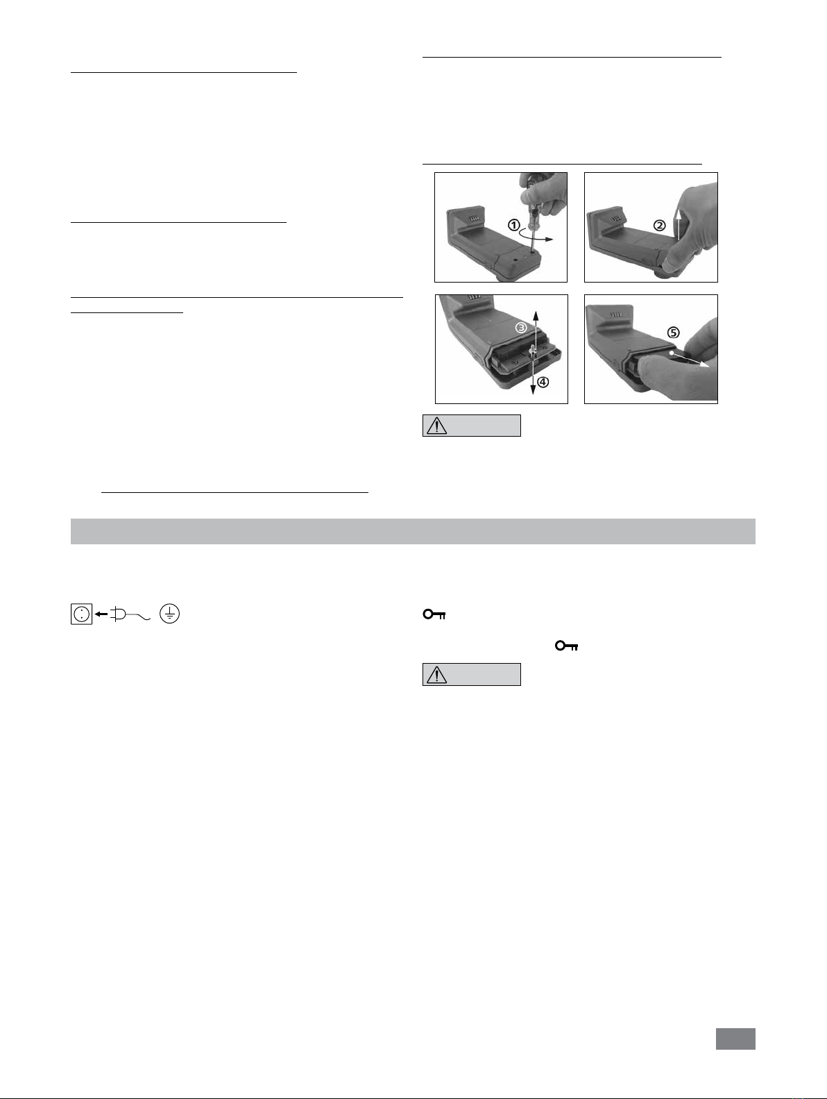
If during operation the battery pack RB 1 (re-
chargeable battery) becomes fully discharged,
the device will continue to run or is shut down depending on the
value settings for exceeding the time and safety speed. If the device
is set so that it continues to run when the battery of the WiCo is
fully discharged, the only means of switching the station off are the
"safe STOP" and the off switch!
Please note the following safety in-
structions for the battery pack RB 1 (re-
chargeable battery):
• Keep the battery pack out of reach of children at all times.
• Store the battery pack in a cool, dry place.
• Never throw the battery pack into a fire. Keep it away from di-
rect sunlight and temperatures above 60 °C. High temperatures
will damage the battery pack and render it unusable. Tempera-
tures above 100 °C may cause it to explode.
• Never throw the battery pack into water or expose it to mois-
ture. Water may lead to a short-circuit, causing the battery pack
to explode.
•
Do not deform or crush the battery pack or damage it in any
other way. This can cause battery fluid to leak and/or the bat-
tery pack to explode.
• When not in use, keep battery packs away from paperclips,
coins, keys, nails, screws or other small metal objects which
could cause the contacts to be bridged. Short-circuiting may
result in an explosion.
• Explosion of a battery pack may release battery fluid and cause
a fire.
• The lithium polymer battery pack must only be used and charged
in IKA®products designed for use with this battery pack.
• When the battery pack is inserted it should slide in easily and
without resistance. Do not force it.
• If the battery pack is removed for an extended period of time,
store it in a sealed plastic bag to prevent short-circuiting due to
moisture or contact with metal components.
• The operating temperature range of the battery pack is from
0 °C to + 45 °C. Note that the battery pack capacity will be
reduced at temperatures below 20 °C.
• Only the rechargeable battery types recommended in the tech-
nical data may be used in the device!
Do not charge batteries that have leaked or that are discol-
ored, deformed or damaged in any other way.
Disposal instructions:
• When disposing of the IKA®battery pack, please tape over the
contacts with adhesive tape to prevent short-circuiting due to
moisture or contact with metal components. Short-circuiting may
result in an explosion.
• Do not throw used battery packs into your household waste. Dis-
pose of them properly in accordance with statutory regulations.
End users are obliged by law to return all used dispos-
able and rechargeable batteries. Throwing them into the
household waste is prohibited. Disposable/rechargeable
batteries containing harmful substances are marked with this
symbol to indicate that they may not be disposed of as house-
hold waste.
• You can return used disposable and rechargeable batteries free
of charge to your local authority collection site or to any battery
retailer. In doing so you will be complying with statutory regula-
tions and helping to protect the environment.
• Batteries must be disposed of in accordance with local and na-
tional regulations.
DANGER
NOTICE
NOTICE
NOTICE
NOTICE
NOTICE
CAUTION

6
Unpacking
• Unpacking:
- Unpack the device carefully.
- Any damage should be notified immediately to the shipping
agent (post, rail or logistic company).
• Delivery scope:
- EUROSTAR 100 P4 control station with a WiCo
-
Extension arm
-
Hexagonal socket screw
-
Hexagon socket offset screw key
-
Chuck key
-
Pt 1000 temperature sensor
-
Protective cover
-
WiCo holder
-
OS 1.0 power supply unit
-
USB 2.0 cable micro A – micro B
-
USB 2.0 cable A – micro B
-
User guide
-
Warranty card
Correct use
• Use:
For mixing/stirring liquids with low and high viscosities by vari-
ous stirring tools.
Intended use: Stand device (chuck points down).
• Range of use (indoor use only):
- Laboratories - Schools
- Pharmacies - Universities
• Wireless remote control:
Before using the wireless link between the WiCo and the labo-
ratory device, first check whether your region is included in the
radio communications approval for the device. If it is not, remote
control can also be performed using a USB cable.
This device is suitable for use in all areas except:
- Residential areas
- Areas that are connected directly to a low-voltage supply net-
work that also supplies residential areas.
The safety of you cannot be guaranteed:
- If the device is operated with accessories that are not supplied or
recommended by the manufacturer
- If the device is operated improperly or contrary to the manufac-
ture’s specifications
- if the device or the printed circuit board are modified by third
parties.
Drive
The rotary knob (B, see Fig. 1) of the WiCo allows the speed of the stirrer to be adjusted over the entire speed range.
Motor protection
The stirring device is suitable for continuous operation. The motor
current is limited electronically. The device has an anti-stall and
anti-overload system.
If a fault occurs, a safety circuit immediately switches off the mo-
tor permanently through a relay in the power board. A fault occurs
if the safe functioning of the device is compromised.
Speed – normal operation
Speed - regulated (no variation in speed):
The speed is monitored and regulated by processor controlled.
The target speed is constantly compared with the actual rota-
tion speed value of the output shaft and variations corrected. This
guarantees a constant speed even if the viscosity of the substance
being stirred changes.
Fluctuations in mains voltage within the permitted tolerance range
have no effect on the quality of regulation and constancy of speed.
The speed is set using the front knob (B, see Fig. 1). During normal
operations the speed value on the display (C, see Fig. 1) corresponds
to the speed of the output shaft in revolutions per minute (rpm).
OS 1.0 power supply unit (for WiCo):
Adapter
England
Adapter
USA, China
Adapter
Australia
Adapter
Europe, Switzerland

7
Accessories must be assembled according to the
following assem-
bly instructions (Fig. 2 to
Fig. 7).
If above conditions are met, the device is
ready for operation after plugging in the
mains plug.
Speed – overload operation
In order to overcome peaks in the load such as arise when a solid
or viscous medium is added, the stirrer can be run for a brief pe-
riod at twice its rated power. When running in the overload range
(for instance if the viscosity has increased at a particular stage of
the process) the speed will be reduced to a degree sucient to
keep the torque on the stirrer shaft within the rated torque of the
device.
The speed is continually adjusted whilst the stirrer is running to
correspond to the operating conditions and so that it matches the
set speed as closely as possible.
Overload status 1:
The device is already running within the overload range, whereby
the actual speed does not match the set speed. This condition is
maintained as long as neither the motor current nor the tempera-
ture exceeds their permissible limit value.
This is indicated by the torque value flashing in the display.
Once the load reduces to a value within the normal range again,
the torque value ceases to flash.
Overload status 2:
If the device is subjected to a fluctuating load which causes the
torque to be more than double the normal torque, the actual
speed of the stirrer shaft is quickly reduced to zero.
Message in the display: Error 4 (see “Error codes” section).
Output shaft
Speed display
The speed is set using the rotary knob (B, see Fig.1) on the front
of the WiCo.
The speed is displayed directly in revolutions per minute (rpm) in
the display (C, see Fig.1) of the WiCo.
Commissioning
Assemble the overhead stirrer and all necessary accessories on a
stable, even, non-slip surface. The overhead stirrer must be se-
cured to a stable stand (e.g. R 2722 or R 2723) with a cross-
sleeve (e.g. R 270). The stirring vessel must always be securely
fixed for safety reasons. You must also ensure that the mounting
device (stand) is set up in such a way that it is not liable to topple
and does not start to move during the stirring procedure.
Securing
The clamping chuck and output shaft permit clamping IKA
®
recom-
mend stirrer tools (see section “Permitted IKA
®
Stirrer tools“).
For safety reason, the stirrer cover must be pushed back into the
opening of the housing so that it is properly closed. This is the only
way to ensure that working with the unit is safe and that media
cannot enter the device.
NOTICE
Please see section “Safety instructions“!
Securing the extension arm to the overhead stirrer
Diagram (see Fig. 2)
Ensure that the extension arm is fitted securely.
Vibration may cause the screw to become loose. It is therefore
necessary for safe use to occasionally check that the extension
arm is attached securely. Tighten the hexagonal socket screw as
required.
Securing the overhead stirrer to the stand
Diagram (see Fig. 3)
First secure the cross sleeve (H) to the stand (I). Then secure the
extension arm (J) of the overhead stirrer in the open side of the
cross sleeve which is facing upwards. Once you have set the po-
sition required for the stirring procedure, firmly tighten the two
clamping bolts (G).
Check that the stirrer is held in position firmly prior to each use and
also at regular intervals. The position of the stirrer must only be
adjusted when the equipment is stationary and the power supply
is disconnected.
Securing the stirring element using the chuck
Diagram (see Fig. 4)
Slide the stirring element (M) into the chuck (L). Tighten the chuck
firmly using the chuck key (K).
The stirring element must only be changed when the equipment is
stationary and the power supply is disconnected.
Securing the stirring shaft protector
Diagram (see Fig. 5)
Use a stirring shaft protector (Q), e.g. R 301, to provide protection
against injury when working with the device.
Use the bolts (U) to attach the plastic half-shell pieces to the stir-
rer (T), as shown in Fig. 5. The screw (S) can be used to adjust the
length of the stirring shaft protector.
Check that the stirring shaft protector is held in position securely
prior to each use and also at regular intervals. The position of the
stirring shaft protector must only be adjusted when the equipment
is stationary and the power supply is disconnected.

8
Switching on the device
Check whether the voltage given on the type plate corresponds to
the available mains voltage.
The socket used must be earthed (fitted
with earth contact).
If these conditions have been met, the machine is ready for opera-
tion when the mains plug is plugged in.
If these conditions are not met, safe operation is not guaranteed
and the machine could be damaged.
Before the first time to use the EUROSTAR stirrer, fasten the
WiCo to
the station with the screw (P, see Fig. 1), so that the rechargeable
battery (RB1 battery pack) in the WiCo can be charged.
After the device has been switched on at the mains switch (A, see
Fig. 1) the device name and software version appear in the display
(C, see Fig. 1) of the WiCo (D, see Fig. 1). After a few seconds a
signal sounds, the last setting of speed is displayed (mode B).
Once
the working screen is displayed, the stirrer is ready for operation.
If the WiCo is switched on and is not attached to the stirrer (the sta-
tion), the green LED bar (G, see Fig. 1) and the green Bluetooth®LED
(F, see Fig. 1) on the stirrer (station) will light up. Make sure that the
speed selected is appropriate for the trial run. If in doubt, use the ro-
tary knob (B, see Fig. 1) to select the slowest speed. To start or stop
the stirrer function, press the rotary knob (B).
The control elements of the WiCo can be disabled by pressing
the button (L
, see Fig. 1
) about 2 seconds, so that no inadvertent
changes are made while the device is running (the lock symbol
appears in the display).
Presse the button (L) about 2 seconds enables the control ele-
ments again (lock cymbol disappears from the display).
In emergency the stirrer (station) can be
switched off by pressing the “safe STOP“
button (I, see Fig.1) on the front of the stirrer. In this case the LED
bar (G, see Fig.1) changes color from green to red, and flashes.
A message appears in the display, advising that the stirrer (station)
has been forcibly switched off. To restart the stirrer, switch the mains
switch (A, see Fig. 1) of the stirrer (station) OFF and ON.
If the Bluetooth®function of the WiCo is active, you can use the
Bluetooth®search button (H
, see Fig. 1
) to search for the WiCo. A
beep signal will be audible even if the WiCo is switched off.
The direction of rotation of the stirrer can be changed by pressing
the “Rev” button (K
, see Fig. 1
) when the stirrer is in stand-by
status (stationary).
Note: The direction of rotation can also be switched using the set-
tings in the “Intermittent Mode“ menu (see the “Explanation
of symbols on the working screen” and “Navigation menu
and menu structure” section, see Fig. 9).
NOTICE
Securing the mixing vessel to the stand
Diagram (see Fig. 7)
First fix the cross sleeve (H) to the stand (I).
Then attach the bracket (Z) of the strap clamp in the open side of
the cross sleeve which is facing upwards according to the position
of stirrer and the mixing vessel, firmly tighten the two clamping
bolts (G).
Clamp the mixing vessel (V) with the flexible clamping band (W) and
secure the flexible band (W) by means of the clamping lever (X).
Attachment of the WiCo to the stirrer
Diagram (see Fig. 1)
Attach the WiCo to the charging contact provided on the station,
and bolt it to the EUROSTAR station with the screw (P).
Connection of the temperature sensor, USB and RS232
cables to the stirrer
Diagram (see Fig. 6)
The USB, RS 232 or temperature sensor cable should be plugged
into the appropriate port after the covers have been removed as
shown in Fig. 6.
Once the EUROSTAR has been connected to the PC using the USB
data cable, it will then transmit information to the Windows oper-
ating system to tell it which device drivers are required. Windows
will then either:
- Load the driver
- Install the driver automatically, if it is not already installed
- Prompt the user to perform a manual installation
Open
http://www.ika.com/ika/lws/download/usb-driver.zip
Changing the RB 1 battery pack in the WiCo
Please comply with the relevant safety instruc-
tions in the "Safety instructions" section for
the RB 1 battery pack!
Charging the RB 1 battery pack (rechargeable battery)
The battery pack of the WiCo can be charged by any of the fol-
lowing means:
- on the EUROSTAR station
- via a USB cable at the PC or station
- via an OS 1.0 power supply unit.
NOTICE

9
Useful information
The stirrer is controlled via a WiCo. If the WiCo is attached to the
EUROSTAR station, data exchange between the stirrer (station)
and WiCo is performed via the contacts (E, Q, see Fig. 1). "Home"
symbol appears on the display of the WiCo. If the WiCo is
connected to the stirrer (station) via a USB (Universal Serial Bus)
cable, the symbol appears. If the WiCo is neither bolted to
the EUROSTAR station nor connected to the stirrer (station) via
a USB cable, the data exchange between the stirrer and WiCo is
performed via Bluetooth®. In this case the Bluetooth®symbol
is displayed.
Depending on the structure of the building, the WiCo can be oper-
ated at a distance of up to 150 m from the EUROSTAR station,
using the Bluetooth
®
connection.
The WiCo can be attached to the stirrer (station), or can be in-
stalled in a safe place easily accessible by you while the stirrer is
running.
If the WiCo is attached to the EUROSTAR station, the recharge-
able battery is automatically recharged via the contacts (Q, see
Fig. 1). The rechargeable battery can also be charged via the USB
port of the WiCo (see “Charging the RB 1 battery pack (re-
chargeable battery)“ in the “Securing“ section).
If the stirrer (station) generates vibration, the
WiCo must be bolted to the stirrer using the
screw (P, see Fig. 1), or positioned remotely from the stirrer (sta-
tion) whilst it is running.
NOTICE
WiCo
Control elements of the WiCo:
Item Designation
M On/Off button: Switching the WiCo on and off
L Lock button: Disable buttons and rotary / push knob
N Menu button: Press it once: main menu is displayed
Press it a second time: back to the working screen
B Rotary/push knob: Navigation, selecting and changing the settings in the menu
O Back button: Return to the previous menu level / reset the torque
K Rev button: Reversal of the direction of rotation
Note: Can be activated only when the station is in stand-by mode.
B
M
O
N
L
K
Working screen at the time of delivery:
Explanation of symbols on the working screen:
The symbols displayed change depending on the
status and settings of the WiCo. The screen be-
low shows the most significant symbols on the
working screen.
The start screen appears for a few seconds after
the WiCo is switched on. The device name and
the software version are displayed. After this, the
following working screen appears automatically
in the display.
Note: The wireless symbol appears only when
the stirrer (station) is switched on.
Bluetooth®:
This symbol means the EUROSTAR station and the WiCo are
communicating via Bluetooth®.
The symbol no longer appears if no Bluetooth®communication is
being performed.
Lock:
This symbol means that the function of the buttons and of the
rotary knob for controlling the WiCo are locked.
The symbol no longer appears if the functions are unlocked once
again by pressing the lock button a second time.
BOperating mode:
This symbol indicates the operating mode currently selected (A,
B, C).
B
0
0
actual rpm
set rpm
Torque: 0Ncm
Reset Torque
Back
Timer:
00:00:00
B
300
99:00:00
actual rpm
rated rpm
45.0 ºC
100 Ncm
Torque:
Temp.:
Timer:
00:00
PC
controlled
LIMIT 300
USB:
This symbol means the station is communicating via a USB cable.
The symbol no longer appears if no USB cable is being used for
communicating with the station.
Home:
This symbol means that the WiCo is connected to the station and
is communicating with the station via the charging contacts.
The symbol no longer appears if the WiCo is removed from the
station.
Battery pack (rechargeable battery):
This symbol indicates the charging status of the RB 1 battery
pack within the WiCo.
The charging symbol appears if the WiCo
- is connected to a PC via a USB cable
- is connected to a station via a USB cable
- is connected to the power supply unit OS 1.0 via a USB cable
- is connected to the station via the charger contacts.
LIMIT Speed limit:
This symbol indicates upper speed limit set for the stirrer. The setting
of the device in delivery status is the maximum permissible speed
of the stirrer.
Temperature sensor:
This symbol appears when the temperature display is active in the
display.

10
Navigation menu and menu structure:
Navigation menu:
Navigation menu: Press the “Menu“ button (N) and turn the rotary/push knob (B)
Press the "Back" button (O) or the "Menu" button (N)
Note: If you press the “Menu“ button (N), the system skips directly back to the working screen.
If you press the “Back“ button (O), the system skips back to the previous display.
Menu
Tempe
Stirring
Press the "Menu" button (N).
Select the menu by turning the rotary/push knob (B) to the right or left to select the desired menu or sub-
menu, which can then be selected by pressing the rotary/push knob.
Press or turn the rotary/push knob (B) again to select the desired menu option and edit the values or set-
tings, or activate/deactivate a function.
Turn the rotary/push knob (B) to "OK" and press the "Back"
button
(O) or "Menu"
button
(N) to end the
procedure and return to the previous menu or working screen.
Note: The menu option activated is highlighted yellow in the display.
Torque Calibration
Stirring
Intermittent Mode
Torque Display
Torque Limit
Speed Limit
Stirring
Speed Limit
Speed Limit
300 rpm
OK
Menu
Back
Menu
Back Back
B
0
0
actual rpm
set rpm
Torque: 0.0 Ncm
Reset Torque
Back
Timer:
00:00:00
Navigation control
elements in the menu
B
O
N
Turbine stirrer
Stirring
Propeller stirrer
Paddle stirrer
Anchor stirrer
Manual
Back
PC
controlled PC control:
This symbol means that either the EUROSTAR station or the
WiCo is connected to a computer and the stirrer is being con-
trolled from the computer.
PR
controlled Program control:
This symbol means the device is controlled by user defined program.
Continuous mode:
This symbol indicates that the stirrer is in continuous mode and
indicates the direction of rotation of the stirrer.
00:00 Intermittent mode:
This symbol indicates that the stirrer is in intermittent mode.
Note: the symbol
00:00
changes the direction of rotation (clockwise
or counterclockwise) and hence the direction of rotation of the stir-
rer if the reversing function “CW/CCW“ is activated in “Intermit-
tent Mode” (see “Intermittent Mode“ section).

11
Factory settings
Menu
Menu structure:
Stirring
Temperature
Timer
Operating Mode
Display
Programs
Safety
Settings
Speed Limit
Torque Limit
Torque Display
Intermittent Mode
Torque Calibration
Probe Temperature
Display
Set
Display
A
B
C
Torque
Temperature
Timer
Programs 1
...
Programs 5
Time Out
Safe Speed
Password
Languages
Units
Display
Sound
Factory Settings
Communication
Information
Manual
Anchor stirrer
Paddle stirrer
...
Run/Stop
CW/CCW
Interval
English
Deutsch
...
Temperature
Background
Brightness
Firmware Update Info
Volume
Key Tone
Device name
Remote Control
Bluetooth
Stirring
Safety
Software
Firmware Update Info
300 rpm
-
-
-
320 Ncm
activated
-
-
00:00 [mm:ss]
00:00 [mm:ss]
-
-
-
00:00:00 [hh:mm:ss]
activated
-
activated
-
activated
-
activated
yes
-
-
00:30 [mm:ss]
100 rpm
000
activated
-
-
activated
-
activated
-
60 %
20 %
activated
100 %
-
IKA ES100P4
activated
-
activated
yes
yes
yes
yes
yes
yes
yes
yes
yes
yes
Run Time
Stop Time
ºC
ºF
Black
White
Standard Mode
Battery mode
WiCo
Other
Max Speed
Max Torque
Interval Run
Interval Stop
Time Out
Safe Speed
Version
Station Version
Operating Mode

12
Menu (details):
Stirring:
Speed Limit:
The “Manual“ option allows you to set the desired maximum
speed limit for the stirrer. The initial setting is the maximum per-
missible speed of the stirrer. If you change this setting, the WiCo
saves the new value for future stirring tasks.
If the “Speed Limit” has been changed, then the speed can be
adjusted only within the new range.
Under the stirrer elements type, the maximum speed limit
is set automatically by the selected stirrer element, e.g. the
maximum speed is limited to 1000 rpm when anchor stirrer
R1330 is selected.
For detailed information, refer to section “
Permitted IKA®stirrer
tools
”.
Torque Limit:
The ”Torque Limit” menu allows you to set the desired maximum
deliverable torque limit. The initial setting is the maximum permis-
sible torque of the device.
If you change this setting, the WiCo saves the new value for fu-
ture stirring tasks.
If the “Torque Limit“ has been changed, the stirrer can deliver an
operating torque only up to the value specified as the maximum
torque limit.
Note: The torque limit can be overload for about 10 seconds. This
is necessary to cater for stirring tasks which require metering and
feeding additives.
Torque Display:
The ”Torque Display” menu allows you to specify that the
torque is shown in the display. A tick shows that the option is
activated.
Note: Pressing the "Back" button while the device is running
resets the torque to 0 Ncm. The Δ symbol then appears in the
display in front of the torque value.
Intermittent Mode:
Symbol rotation
direction
Chuck rotation
direction Graph
CW
Time
Speed
Factory setting: continuous mode
CW
Time
Speed
Function “Run/Stop“ is activated:
The run time and stop time can be set separately.
CW/CCW
Time
Speed
Functions “Run/Stop“ and “CW/CCW“ is activated:
The run time and stop time can be set separately.
Note: The run time is the same length in clockwise and counter-
clockwise direction.
CW/CCW
Time
Speed
Function “CW/CCW“ is activated:
The clockwise and counterclockwise running time can be set
independently.
∞ / CW...
Run-Stop-Run / CW ...
Run-Stop-Run (CW) / Run-Stop-Run (CCW) ...
Run (CW) / Run (CCW) ...
Fig. 9
Torque Calibration:
This menu allows the torque to be calibrated. All torque resulting from bearing friction is excluded from the torque calculation. This is
performed with no stirrer element attached. A duration of 30 seconds and speed of 50 rpm are set automatically.
Note: Calibration can be performed only when a USB cable is being used. For this, remove the WiCo from the station (see "Interfaces
and outputs" section, figure “Connection capability: WiCo to the station“).

13
Operating Mode:
Operating Mode A:
In this operating mode, the set speed is not saved when the current
run comes to an end or the device is switched off.
Operating Mode B:
In this operating mode, the set speed is saved when the current
run comes to an end or the device is switched off, and the value
can be changed.
Operating mode C:
In this operating mode, the set speed is saved when the current
run comes to an end or the device is switched off, and the value
cannot be changed.
Temperature:
In the ”Temperature” menu you can specify that the temperature
sensor is displayed on the display/working screen. A tick shows that
the option is activated. The precondition for this is that a tempera-
ture sensor is connected to the station. If no temperature sensor
is connected, or an error is present or the temperature rises above
350 °C, three dashes are shown as the temperature value.
Note:
Please comply with the temperature measurement range of
the external temperature sensor specified in the "Technical data"
section. The temperature display can be in either °C or °F (see the
”Settings“ menu).
Timer:
In the ”Timer” menu you can specify that the timer is displayed
on the display/working screen. A tick shows that the option is ac-
tivated. This setting allows you to specify the actual time for the
stirring procedure.
A default time can also be set for the timer. This setting allows
you to start the stirring task for a standard time. The device stops
automatically after expiry of the set time, and the set time used for
the stirring procedure appears in the display.
Note:
You can stop the stirring function before expiry of the set
time. In this case the countdown of the timer is interrupted.
Display:
In the “Display“ menu you can specify what information will be
displayed on the main screen.
Note: If the ”Torque”option is activated, by pressing the ”Back“
button you can reset the current torque to 0 Ncm as a reference
value. At the same time the Δ appears in front of the Ncm unit.
Programs:
Under menu "Programs", 5 user-defined speed (rpm)-time pro-
files can be created. In addition, you could define the intermittent
mode is activated or not in the programs.
If the intermittent mode is activated, the run time/stop time value
from "Intermittent Mode" setting will be taken.
Note: If user need to activate the intermittent mode in one segment
of a program, he should set the "Run time/Stop time" in menu
option "Interval", meanwhile activate the "Run/Stop" function in
menu option "Intermittent Mode" (see section "Stirring").
Once a programs has been selected, the following options are avail-
able.
Start: Start the selected program upon request.
When the selected program is started by pressing on menu option
"Start" with
rotary/push knob, screen reminds you to confirm the
program control. Press "OK" with
rotary/push knob to start the
program control.
Edit: Edit the selected program parameters.
Start to edit the selected program parameters by pressing on menu
option "Edit" with rotary/push knob. You can edit, delete or insert
one selected program segment in the program.
When user edits the program time for at least one segment, tick (
√
)
for respective program will appear.
Delete: Deletes the selected program.
If a selected program is deleted by pressing on menu option "Delete"
with rotary/push knob, all the program parameters will be emptied.
The tick (√) disappears.
Details for editing the program:
When a program is being edited, following screen appears.
PROGRAM 1
Seg
No.
rpm Time
hh:mm
Interm.
Mode
Edit Delete Insert
1
2
3
4
5
0 00:00 No
In this program, user can define up to 5 seg-
ments. The selected segment is highlighted.
Then, you can edit, delete or insert a seg-
ment in this program.
When the "Back" button is pressed after
editing, the program is save automatically.
Edit:
When the highlighted "edit" symbol appear on the right top of
the screen, you could change the speed (rpm), time value or inter-
mittent mode setting.
Note: The speed (rpm) value can be changed during the speed
limit range of the device. The time can be set from 1 minute to
10 hours.
Delete:
When delete a highlighted segment, the settings will be emptied. The
section jump to next segment.
Insert:
With the insert option, a new segment will be insert below the
selected segment. The default settings for the new segment are as
following:
rpm: 0
Time (hh:mm): 00:01
Intermittent Mode: No

14
View the program in graph:
After a program is being edited, press the "Back" button to save the
settings. Press the "Back" button again, the screen back to follow
screen.
If no button or knob is pressed or turned for 5 seconds, pictorially
respective program will be shown.
rpm
150
300
Seg No.: 1
rpm: 150
Time (hh:mm): 00:10
Interm. Mode: Yes
PROGRAM 1 Detail
rpm
150
300
PROGRAM 1 Detail
rpm
150
300
Seg No.: 2
rpm: 150
Time (hh:mm): 00:10
Interm. Mode: No
PROGRAM 1 Detail
Press the rotary/push knob on option "Detail", the detailed set-
tings of every segment can be seen.
Turn the rotary/push knob, the details screen of every segment can
be switched.
Programs
Start Edit Delete
Program 1
Program 2
Program 3
Program 4
Program 5

15
Example for editing the program:
PROGRAM 1
Seg
No.
rpm Time
hh:mm
Interm.
Mode
Edit Delete Insert
1
2
3
4
5
000:00 No
edit
PROGRAM 1
Seg
No.
rpm Time
hh:mm
Interm.
Mode
Edit Delete Insert
1
2
3
4
5
0 00:00 No
PROGRAM 1
Seg
No.
rpm Time
hh:mm
Interm.
Mode
1
2
3
4
5
000:00 No
Edit Delete Insert
PROGRAM 1
Seg
No.
rpm Time
hh:mm
Interm.
Mode
Edit Delete Insert
1
2
3
4
5
100 00:00 No
edit PROGRAM 1
Seg
No.
rpm Time
hh:mm
Interm.
Mode
Edit Delete Insert
1
2
3
4
5
100 00:00 No
PROGRAM 1
Seg
No.
rpm Time
hh:mm
Interm.
Mode
Edit Delete Insert
1
2
3
4
5
100 00:00 No
PROGRAM 1
Seg
No.
rpm Time
hh:mm
Interm.
Mode
Edit Delete Insert
1
2
3
4
5
100 00:00 No
edit PROGRAM 1
Seg
No.
rpm Time
hh:mm
Interm.
Mode
Edit Delete Insert
1
2
3
4
5
100 00:10 No
edit PROGRAM 1
Seg
No.
rpm Time
hh:mm
Interm.
Mode
Edit Delete Insert
1
2
3
4
5
100 00:10 No
PROGRAM 1
Seg
No.
rpm Time
hh:mm
Interm.
Mode
Edit Delete Insert
1
2
3
4
5
100 00:10 Yes
PROGRAM 1
Seg
No.
rpm Time
hh:mm
Interm.
Mode
Edit Delete Insert
1
2
3
4
5
100 00:10 Yes
PROGRAM 1
Seg
No.
rpm Time
hh:mm
Interm.
Mode
Edit Delete Insert
1
2
3
4
5
100
0
00:10
00:00
Yes
No
Programs
Start Edit Delete
Program 1
Program 2
Program 3
Program 4
Program 5
PROGRAM 1
Seg
No.
rpm Time
hh:mm
Interm.
Mode
1
2
3
4
5
0 00:00 No
Edit Delete Insert
Back
Programs
Start Edit Delete
Program 1
Program 2
Program 3
Program 4
Program 5
Programs
Edit Delete
Program 1
Program 2
Program 3
Program 4
Program 5
Start
Programs
Edit Delete
Program 1
Program 2
Program 3
Program 4
Program 5
Start
PROGRAM 1
Seg
No.
rpm Time
hh:mm
Interm.
Mode
Edit Delete Insert
1
2
3
4
5
100
150
200
250
300
00:10
00:10
00:20
00:10
00:30
Yes
No
No
No
Yes
Back
rpm
150
300
PROGRAM 1 Detail
Edit speed (rpm)
Edit time (hh:mm)
Edit intermittent mode (Yes/No)
Program diagram
5 s
Note: When intermittent mode is ac-
tive, dashed line is used to represent
the speed (rpm).
PROGRAM 1
Seg
No.
rpm Time
hh:mm
Interm.
Mode
Edit Delete Insert
1
2
3
4
5
100 00:10
edit
Yes
PROGRAM 1
Seg
No.
rpm Time
hh:mm
Interm.
Mode
Edit Delete Insert
1
2
3
4
5
100 00:10
edit
No
PROGRAM 1
Seg
No.
rpm Time
hh:mm
Interm.
Mode
Edit Delete Insert
1
2
3
4
5
100 00:10 No
rpm
150
300
Seg No.: 1
rpm: 100
Time (hh:mm): 00:10
Interm. Mode: Yes
PROGRAM 1 Detail
rpm
150
300
Seg No.: 2
rpm: 150
Time (hh:mm): 00:10
Interm. Mode: No
PROGRAM 1 Detail

16
Safety:
Time Out:
In the “Time Out“ menu, you can set a time limit. This time limit
applies if there is a communication failure between the station
and the WiCo or the communication range is exceeded. The sta-
tion will continue to run at the set speed until the set time has
expired. After that the stirrer (station) will continue to run at the
set safe speed (see the "Safe speed" menu).
Note: The initial setting for the time limit is 30 seconds. You can
set a value of up to 60 minutes for this time limit.
If the intermittent mode is activated, the sta-
tion immediately switches to run at the set
safe speed, or the set speed if that is less than the safe speed.
Safe Speed:
In the “Safe Speed“ menu, you can specify a speed that is appropri-
ate and safe for the stirring task. The safe speed applies if there is a
communication failure between the station and the WiCo or the
communication range is exceeded.
Note: The initial setting of the safe speed is 100 rpm, and is imple-
mented after expiry of the time limit (see "Time out").
Password:
In the “Password“ menu, you can protect the WiCo settings using a
password (factory setting: 000).
Settings:
Languages:
The “Languages“ option allows you to select the desired lan-
guage by turning and pressing the rotary/push knob (B). A tick
indicates the language that is set for the system.
Units:
The ”Units“ option allows you to select the desired unit for dis-
playing the temperature. The choice is between ”°C” or ”°F” and
is made by turning and pressing the rotary/push knob (B). A tick
indicates the unit that is set for the system.
Display:
The ”Display“ option allows you to change the background
color and brightness of the working screen.
The user can also select to activate or inactivate the “Firmware
Update Info” screen at the starting of the Wireless Controller. A
tick shows that the option is activated.
Sound:
The ”Sound” option allows you to activate/deactivate the key-
press sound and to set the volume.
Factory Settings:
Select the ”Factory Settings” option by turning and pressing
the rotary/push knob. The system requests confirmation to recre-
ate the factory settings. Pressing the ”OK” button resets all the
system settings to the original standard values set at dispatch
from the factory (see "Menu structure").
Communication:
The ”Bluetooth
®
” option allows you to activate/deactivate the
”Bluetooth
®
” function. A tick shows that the option is activated.
Information:
The ”Information” option offers you an overview of the most im-
portant system settings of the stirrer.
NOTICE

17
Interfaces and outputs
The device can be operated in “Remote” mode via an RS 232 or
USB interface using the laboratory software labworldsoft®.
The RS 232 interface at the back of the device is fitted with a
9-pole SUB-D port which can be connected to a PC. The pins are
assigned serial signals.
The USB port at the rear of the stirrer is used for the connection
between the PC and the WiCo. The WiCo also has a USB port,
located on its right side. It can also be used to connect to a PC for
“remote control“.
Note: Please comply with the system requirements together with the
operating instructions and help section included with the software.
USB interface:
The Universal Serial Bus (USB) is a serial bus for connecting the
device to the PC. Equipped with USB devices can be connected to
a PC during operation (hot plugging). Connected devices and their
properties are automatically recognized. Use the USB interface in
conjunction with labworldsoft®for operation in “Remote” mode
and also to update the firmware.
Installation:
First, download the latest driver for IKA®devices with USB inter-
face from:
http://www.ika.com/ika/lws/download/usb-driver.zip.
Install the driver by running the setup file. Then connect the IKA®
device through the USB data cable to the PC. The data communi-
cation is via a virtual COM port. Configuration, command syntax
and commands of the virtual COM ports are as described in RS
232 interface.
Serial interface RS 232:
Configuration
- The functions of the interface connections between the stirrer
machine and the automation system are chosen from the signals
specified in EIA standard RS 232 in accordance with DIN 66 020
Part 1.
- For the electrical characteristics of the interface and the alloca-
tion of signal status, standard RS 232 applies in accordance with
DIN 66 259 Part 1.
- Transmission procedure: asynchronous character transmission in
start-stop mode.
- Type of transmission: full duplex.
- Character format: character representation in accordance with
data format in DIN 66 022 for start-stop mode. 1 start bit; 7
character bits; 1 parity bit (even); 1 stop bit.
- Transmission speed: 9600 bit/s.
- Data flow control: none
- Access procedure: data transfer from the stirrer machine to the
computer takes place only at the computer’s request.
Command syntax and format:
The following applies to the command set:
- Commands are generally sent from the computer (Master) to the
stirrer machine (Slave).
- The stirrer machine sends only at the computer’s request. Even
fault indications cannot be sent spontaneously from the stirrer
machine to the computer (automation system).
- Commands are transmitted in capital letters.
- Commands and parameters including successive parameters are
separated by at least one space (Code: hex 0x20).
- Each individual command (incl. parameters and data) and each
response are terminated with Blank CR LF (Code: hex 0x20 hex
0x0d hex 0x20 hex 0x0A) and have a maximum length of 80
characters.
- The decimal separator in a number is a dot (Code: hex 0x2E).
The above details correspond as far as possible to the recommen-
dations of the NAMUR working party (NAMUR recommendations
for the design of electrical plug connections for analogue and
digital signal transmission on individual items of laboratory control
equipment, rev. 1.1).
The NAMUR commands and the additional specific IKA®co-
mmands serve only as low level commands for communication
between the stirrer machine and the PC. With a suitable terminal
or communications programme these commands can be transmit-
ted directly to the stirrer equipment. The IKA®software package,
labworldsoft®, provides a convenient tool for controlling stirring
equipment and collecting data under MS Windows, and includes
graphical entry features, for motor speed ramps for example.
The following table summarises the (NAMUR) commands under-
stood by the IKA®control equipment.
NAMUR Commands
Function
IN_NAME Read device name
IN_PV_3 Read PT1000 value
IN_PV_4 Read current speed value
IN_PV_5 Read current torque value
IN_SP_4 Read rated speed value
IN_SP_5 Read the torque limit value
IN_SP_6 Read the speed limit value
IN_SP_8 Read the safety speed value
OUT_SP_4 Adjust the rated speed value
OUT_SP_5 Adjust the torque limit value
OUT_SP_6 Adjust the speed limit value
OUT_SP_8 Adjust the safety speed value
START_4 Start the motor
STOP_4 Stop the motor
RESET Switch to normal operating mode
OUT_MODE_n (n= 1 or 2) Change the direction of rotation
IN_MODE Read the direction of rotation
PC 1.1 Cable (station to PC):
Required for connecting the 9-pin socket to a PC.
1
2 RxD
3 TxD
4
5 GND
6
7 RTS
8 CTS
9
1
RxD 2
TxD 3
4
GND 5
6
RTS 7
CTS 8
9
PC
1
2
3
4
5
6
7
8
9
9
8
7
6
5
4
3
2
1

18
micro B
micro A USB micro B USB micro A
Connection capability: WiCo to the EUROSTAR station:
Connection capability: EUROSTAR station to the computer:
A
USB micro B USB A
9-pin RS 232 9-pin RS 232
or
micro B
A
USB micro B USB A
micro B
or
A
9-pin RS 232 9-pin RS 232
USB micro B USB A
micro B
USB A
USB A
USB A
USB 2.0 cable micro A – micro B
USB 2.0 cable
USB A – micro B
USB 2.0 cable
USB A – micro B
PC 1.1 cable
USB 2.0 cable
USB A – micro B
PC 1.1 cable

19
Maintenance and cleaning
The device is maintenance-free. It is only subject to the natural
wear and tear of components and their statistical failure rate.
Cleaning:
For cleaning disconnect the main plug!
Use only cleaning agents which have been approved by IKA®to
clean IKA®devices.
Dirt Cleaning agent
Dyes isopropyl alcohol
Construction materials
water containing tenside/isopropyl alcohol
Cosmetics
water containing tenside/
isopropyl alcohol
Foodstuffs
water containing tenside
Fuels
water containing tenside
For materials which are not listed, please request information from
IKA®application support.
Wear protective gloves during cleaning the devices.
Electrical devices may not be placed in the cleansing agent for the
purpose of cleaning.
Do not allow moisture to get into the device when cleaning.
Before using another than the recommended method for clean-
ing or decontamination, you must ascertain with IKA®that this
method does not destroy the device.
Spare parts order:
When ordering spare parts, please give:
- machine type
- manufacturing number, see type plate
-
item and designation of the spare part see
www.ika.com,
spare parts diagram and spare parts list
- Software version.
Repair:
Please send in device for repair only after it has been
cleaned and is free from any materials which may consti-
tute a health hazard.
For this, you should request the “Decontamination Certifi-
cate” from IKA®, or use the download printout of it from the
IKA®website www.ika.com.
If you require servicing, return the device in its original packaging.
Storage packaging is not sucient. Please also use suitable trans-
port packaging.
Warranty
In accordance with IKA®warranty conditions, the warranty period
is 24 months. For claims under the warranty please contact your
local dealer. You may also send the machine direct to our factory,
enclosing the delivery invoice and giving reasons for the claim. You
will be liable for freight costs.
The warranty does not cover worn out parts, nor does it apply
to faults resulting from improper use, insucient care or mainte-
nance not carried out in accordance with the instructions in this
operating manual.
Error codes
The fault is shown by an error message in the display (C) as following if the error occurs, e.g. Error 4.
Proceed as follows in such cases:
Switch the device switch (A) off.
Remove the stirrer tool and remove the device from the assembly.
Reduce the speed and switch on (device switch (A)) the device without the stirrer tool.
Error Cause Effect Solution
Error 2 Motor current sensor fault motor off - Switch off the device
Error 3 Temperature inside device is too high motor off - Switch off the device and allow it to cool down
Error 4 Motor blockage or overload motor off - Switch off the device
- Decrease the load on the motor and restart again
Error 8 Speed sensor fault or overload motor off - Switch off the device
Error 21 Safety relay fault motor off - Switch off the device
If the actions described fails to resolve the fault or another error code is displayed then take one of the following steps:
- Contact the service department
- Send the device for repair, including a short description of the fault.

20
Accessories
R 2722 H-stand
R 2723 Telescopic stand
R 270 Cross sleeve
R 271 Cross sleeve
RH 5 Strap clamp
R 301 Stirrer shaft protection
R 301.1 Support holder
PC 1.1 Cable
H 70 Extension cable
H 62.51 Stainless steel sensor
H 66.51 Stainless steel sensor, glass-coated
R 1330 Anchor stirrer 1000
R 1331 Anchor stirrer 1000
R 1333 Anchor stirrer 800
R 1375 Paddle stirrer 800
R 1376 Paddle stirrer 800
R 1342 Propeller stirrer 2000
R 1345 Propeller stirrer 800
R 1381 Propeller stirrer 2000
R 1382 Propeller stirrer 2000
R 1385 Propeller stirrer 800
R 1388 Propeller stirrer 400
R 1389 Propeller stirrer, PTFE 800
Permitted IKA®stirrer tools
max. speed
(rpm)
max. speed
(rpm)
R 1311 Turbine stirrer 2000
R 1312 Turbine stirrer 2000
R 1313 Turbine stirrer 800
See more accessories on www.ika.com.
Table of contents
Other IKA Laboratory Equipment manuals

IKA
IKA mini G User manual

IKA
IKA LR-2.ST User manual

IKA
IKA C 1.30 User manual

IKA
IKA C-MAG HS7 User manual

IKA
IKA KS 130 basic User manual

IKA
IKA Vibrax VXR basic User manual

IKA
IKA Lab Disc IKAMAG User manual

IKA
IKA 20015943 User manual

IKA
IKA RW20 digital User manual

IKA
IKA ULTRA-TURRAX T 18 digital User manual
Popular Laboratory Equipment manuals by other brands

Efkon
Efkon EFAS user guide

ELITechGroup
ELITechGroup AEROSPRAY TB Applications manual

Applied Photonics
Applied Photonics LIBS-6 user manual

Mitutoyo
Mitutoyo MICROPAK-2LA user manual

Bayer HealthCare
Bayer HealthCare Clinitek Status Operator's manual

Neural Analytics
Neural Analytics Lucid In-Service Presentation