manuals.online logo
Brands
  1. Home
  2. •
  3. Brands
  4. •
  5. Immergas
  6. •
  7. Boiler Supplies
  8. •
  9. Immergas 3.021378 User manual

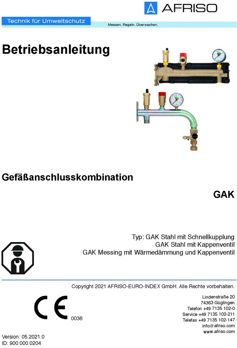
Immergas 3.021378 User manual

L'installazione e la manutenzione devono essere eettuate in ottemperanza
alle normative vigenti, secondo le istruzioni del costruttore e da parte di
personale abilitato nonché professionalmente qualicato, intendendo per
tale quello avente specica competenza tecnica nel settore degli impianti,
come previsto dalla Legge.
INFORMAZIONI GENERALI.
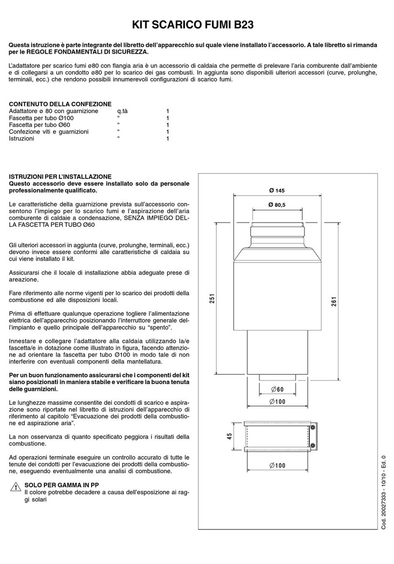
Il presente kit è installabile con uscita destra o sinistra inoltre è possibile
decidere se installare il separatore a parete o a basamento.
Il separatore idraulico rende indipendenti il circuito primario e il circuito
secondario.
Installation and maintenance must be performed in compliance with the
regulations in force, according to the manufacturer's instructions and by
professionally qualied sta, intending sta with specic technical skills
in the plant sector, as envisioned by the Law.
GENERAL INFORMATION.
is kit can be installed with right or le outlet. It is also possible to decide
whether to install the separating device on the wall or oor.
e hydraulic separating device makes the primary circuit and the second-
ary circuit independent.
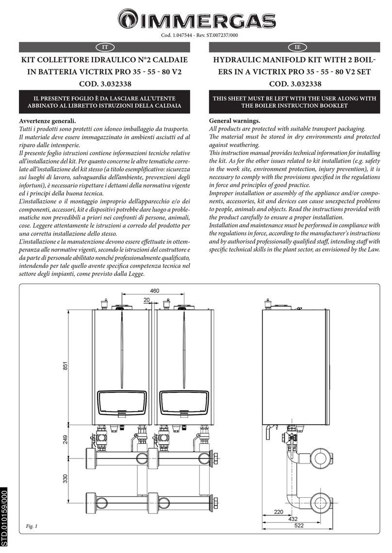
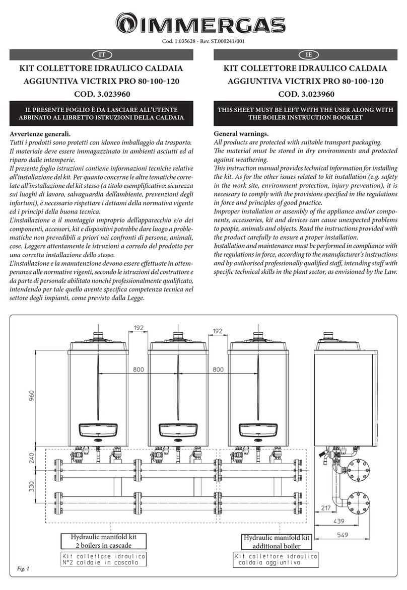
KIT SEPARATORE IDRAULICO PER CALDAIE
IN BATTERIA POTENZA 400kW
3.021378
HYDRAULIC SEPARATING DEVICE KIT
FOR 400KW POWER BOILER SETS
3.021378
IT IE
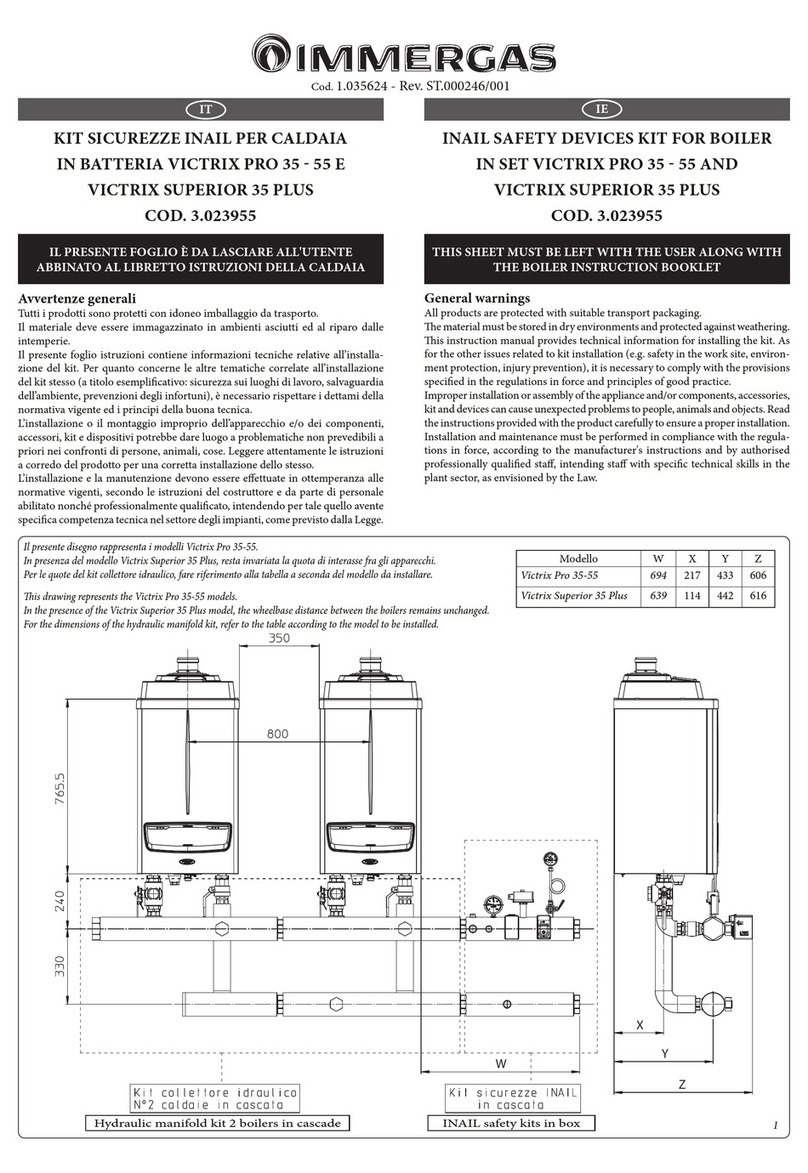
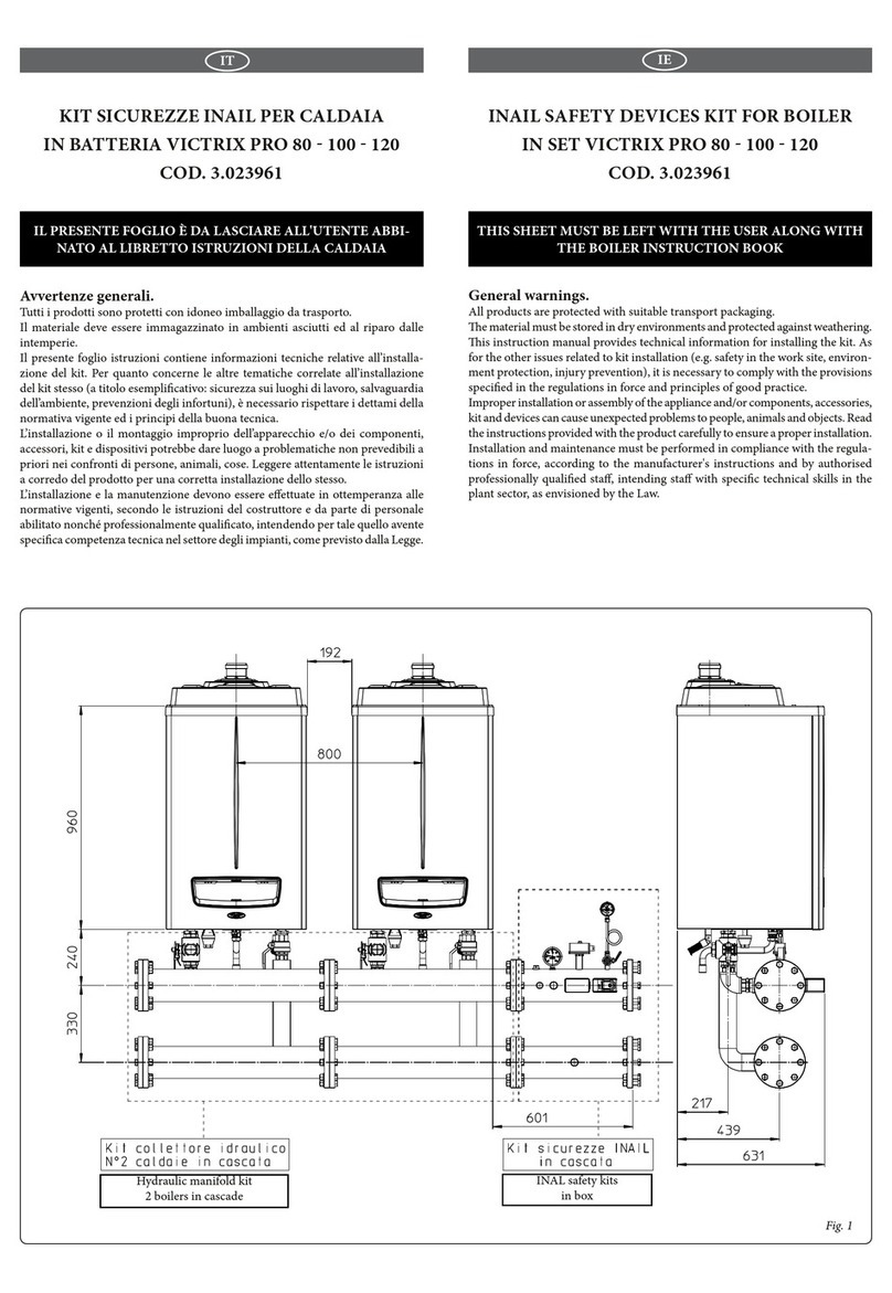
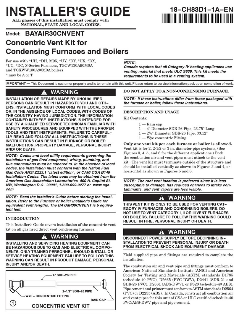
THIS SHEET MUST BE LEFT WITH THE USER ALONG WITH
THE BOILER INSTRUCTION BOOK
IL PRESENTE FOGLIO È DA LASCIARE ALL'UTENTE ABBINATO AL
LIBRETTO ISTRUZIONI DELLA CALDAIA
INSTALLAZIONE A BASAMENTO
FLOORSTANDING INSTALLATION
Fig. 1
XX
==
673
450
170170
452 330
150 150
34
346
538 256
620
150
150
12
3
4
1
272
252
121 121
Composizione kit:
Rif. Qtà Descrizione
1 1 Separatore idraulico (contenuto 69 litri)
2A 1 Supporto per installazione a parete lato G 2" 1/2
2B 1 Supporto per installazione a parete lato DN 100
3 1 Distanziere per separatore
4 2 Supporto per installazione a pavimento
5 2 Guarnizioni piane 72 x 55 x 2
6 12 Viti autolettanti M6 X 15
7 6 Viti per tassello 8 x 80
8 6 Tassello nylon 12 x 60
9 16 Bullone M12 x 50
10 2 Guarnizioni piane DN100
11 16 Rondella per viti M12
12 16 Dado M12
Kit composition:
Ref. Qty Description
1 1
Hydraulic separator device (content 69 litres)
2A 1 G 2" 1/2 support for wall installation
2B 1 DN 100 support for wall installation
3 1 Spacer for separating device
4 2 Support for oor installation
5 2 72 x 55 x 2 at gaskets
6 12 M6 X 15 Self-threading screws
7 6 8 X 80 hex head screws
8 6 12 x 60 nylon masonry plug
9 16 M12 x 50 bolt
10 2 DN100 at gasket
11 16 Washer for M12 screw
12 16 M12 nut Fig. 3
Fig. 2
INSTALLAZIONE A PARETE
WALL INSTALLATION
INSTALLAZIONE A BASAMENTO
FLOORSTANDING INSTALLATION
2A
2B
6
1
7
8
3
6x6
x6
1
4
4
8
7
5
9
11 12
10
INSTALLAZIONE GUARNIZIONI
FLAT GASKETS INSTALLATION
MONTAGGIO KIT.
Per eettuare il montaggio del kit procedere nel seguente modo:
Attenzione: le misure di ssaggio indicate in gura 1 sono indicative e
comprensive del kit "Sicurezze ISPESL" optional.
Per il corretto montaggio far riferimento alla propria congurazione
idraulica.
• Installazione a parete Modelli Victrix 90 - 115.
- Eettuare n° 6 fori Ø 12 utilizzando le misure indicate in gura 1 riferite
alla piastra di ssaggio (rif. 3 g. 2).
- Inlare i 6 tasselli (8) nei fori.
- Fissare il distanziere (3) al muro mediante le 6 viti con tassello (7).
- Aancare i 2 supporti verticali (2) e ssarli alla staa (3) mediante le 6
viti autolettanti (6).
- Appoggiare il separatore idraulico (1) sui supporti (2).
- Eettuare i collegamenti idraulici interponendo le relative guarnizioni
(5 e 10).
Una volta eettuato il montaggio del kit completo eettuare una verica
di tenuta del circuito idraulico secondo quanto prescritto dalla normativa
vigente.
• Installazione a parete Modelli Victrix 50 - 75.
N.B.: per questa installazione non sono necessari il distanziere (3) e le
viti di ssaggio (6).
- Eettuare n° 6 fori Ø 12 utilizzando le misure indicate in gura 1 riferite
al supporto (2).
- Inlare i 6 tasselli (8) nei fori.
- Aancare i 2 supporti verticali (2) e ssarli al muro mediante le 6 viti
per tassello (7).
- Appoggiare il separatore idraulico (1) sui supporti (2).
- Eettuare i collegamenti idraulici interponendo le relative guarnizioni
(5 e 10).
Una volta eettuato il montaggio del kit completo eettuare una verica
di tenuta del circuito idraulico secondo quanto prescritto dalla normativa
vigente.
• Installazione a basamento.
- Eettuare n° 4 fori Ø 12 utilizzando le misure indicate in gura 1 riferite
al supporto (4).
- La quota "XX" rappresenta la distanza dal muro rispetto all'asse del
separatore, per i modelli Victrix 50 - 75 è 436 mm per i modelli Victrix
90 - 115 è 470 mm.
- Inlare i 4 tasselli (8) nei fori.
- Aancare i 2 supporti (4) e ssarli al pavimento mediante le 4 viti per
tassello (7).
- Appoggiare il separatore idraulico (1) sui supporti (7).
- Eettuare i collegamenti idraulici interponendo le relative guarnizioni
(5 and 10).
Una volta eettuato il montaggio del kit completo eettuare una verica
di tenuta del circuito idraulico secondo quanto prescritto dalla normativa
vigente.
KIT ASSEMBLY.
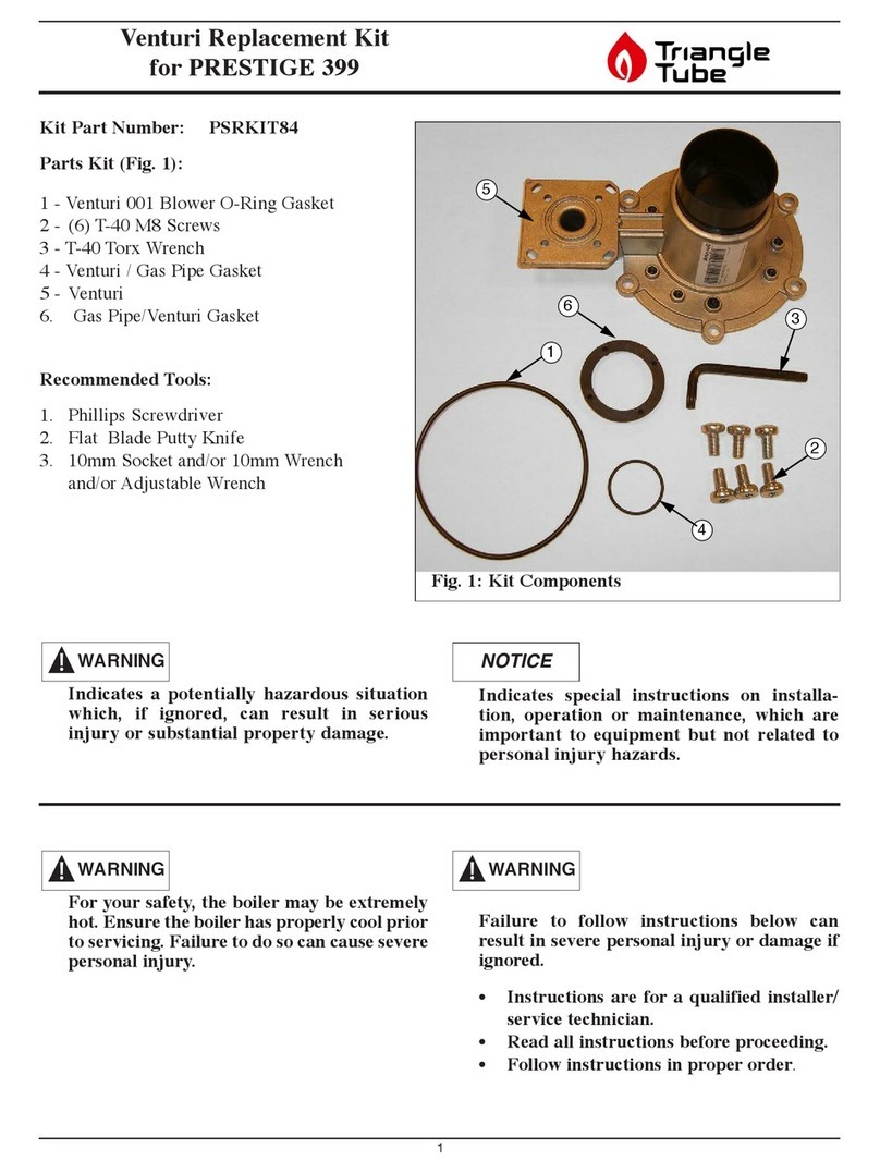
Proceed as follows to assemble the kit:
Important: the xing measurements indicated in gure are indicative and
include the optional "ISPESL safety kits".
For correct mounting, refer to its hydraulic conguration.
• Victrix 90 - 115 models wall installation.
- Make n° 6 holes with Ø 12 using the measurements indicated in gure
1 referring to the xing plate (ref. 3 g. 2).
- Insert 6 plugs (8) into the holes.
- Fix the spacer (3) to the wall using the 6 screws with plug (7).
- Flank the two vertical supports (2) and x them to the bracket (3) using
the 6 self-threading screws (6).
- Place the hydraulic separating device (1) on the supports (2).
- Make the hydraulic connections, positioning the relative gaskets (5).
Once the kit has been mounted completely, check the tightness of the hy-
draulic circuit according to that prescribed by the Standard in force.
• Victrix 50 - 75 models wall installation.
N.B.: the spacer (3) and the fastening screws (6) are not necessary for this
installation.
- Make n° 6 holes with Ø 12 using the measurements indicated in gure
1 referring to the support (2).
- Insert 6 plugs (8) into the holes.
- Flank the two vertical supports (2) and x them to the wall using the 6
self-threading screws (7).
- Place the hydraulic separating device (1) on the supports (2).
- Make the hydraulic connections, positioning the relative gaskets (5).
Once the kit has been mounted completely, check the tightness of the hy-
draulic circuit according to that prescribed by the Standard in force.
• Floor-standing installation.
- Make n° 4 holes with Ø 12 using the measurements indicated in gure
1 referring to the support (4).
- e "XX" measurement represents the distance from the wall with
respect to the axis of the separating device. For Victrix 50 - 75 models
it is 436 mm, for Victrix 90 - 115 models it is 470 mm
- Insert 4 plugs (8) into the holes.
- Flank the two supports (4) and x them to the oor using the 4 self-
threading screws (7).
- Place the hydraulic separating device (1) on the supports (7).
- Make the hydraulic connections, positioning the relative gaskets (5).
Once the kit has been mounted completely, check the tightness of the hy-
draulic circuit according to that prescribed by the Standard in force.
Cod. 1.031477 Rev. 15.033976/001
Legenda:
1 - Valvola sfogo aria
2 - Rubinetto intercettazione
3 - Attacco per sonda (non fornita)
4 - Separatore idraulico (Contenuto 69 litri)
5 - Rubinetto di svuotamento
Key:
1 - Vent valve
2 - Interception cock
3 - Attachment for probe (not supplied)
4 - Hydraulic separator device (content 69 litres)
5 - Draining valve
Fig. 4
DIMENSIONI PRINCIPALI. MAIN DIMENSIONS.

Other Immergas Boiler Supplies manuals

Immergas 3.031186 Product manual

Immergas

Immergas 3.031186 Product manual

Immergas 3.023960 User manual

Immergas

Immergas 3.023960 User manual

Immergas VICTRIX PRO 35 V2 SET User manual

Immergas

Immergas VICTRIX PRO 35 V2 SET User manual

Immergas VICTRIX PRO V2 User manual

Immergas

Immergas VICTRIX PRO V2 User manual

Immergas Victrix TT Series Product manual

Immergas

Immergas Victrix TT Series Product manual

Immergas 3.012944 User manual

Immergas

Immergas 3.012944 User manual

Immergas 3.030323 User manual

Immergas

Immergas 3.030323 User manual

Immergas 3.020934 User manual

Immergas

Immergas 3.020934 User manual

Immergas 3.026302 User manual

Immergas

Immergas 3.026302 User manual

Immergas INAIL VICTRIX PRO 80 User manual

Immergas

Immergas INAIL VICTRIX PRO 80 User manual

Immergas Victrix Pro 35-55 User manual

Immergas

Immergas Victrix Pro 35-55 User manual

Immergas 3.021377 User manual

Immergas

Immergas 3.021377 User manual

Immergas Victrix Superior KW X User manual

Immergas

Immergas Victrix Superior KW X User manual

Immergas VICTRIX PRO 35 V2 SET User manual

Immergas

Immergas VICTRIX PRO 35 V2 SET User manual

Immergas 3.018911 User manual

Immergas

Immergas 3.018911 User manual

Immergas VICTRIX SUPERIOR KIT User manual

Immergas

Immergas VICTRIX SUPERIOR KIT User manual

Immergas 3.014083 User manual

Immergas

Immergas 3.014083 User manual

Immergas 3.020355 User manual

Immergas

Immergas 3.020355 User manual

Immergas 3.032852 User manual

Immergas

Immergas 3.032852 User manual

Immergas 3.031483 Product manual

Immergas

Immergas 3.031483 Product manual

Immergas VICTRIX PRO 35 User manual

Immergas

Immergas VICTRIX PRO 35 User manual

Immergas 3.032264 Product manual

Immergas

Immergas 3.032264 Product manual

Immergas 3.015266 User manual

Immergas

Immergas 3.015266 User manual

Immergas VICTRIX PRO 35 V2 Setup guide

Immergas

Immergas VICTRIX PRO 35 V2 Setup guide

Popular Boiler Supplies manuals by other brands

Bosch Condens 8300i W installation instructions

Bosch

Bosch Condens 8300i W installation instructions

Viessmann KW10A Operating instructions and user's information manual

Viessmann

Viessmann KW10A Operating instructions and user's information manual

TriangleTube CCRKIT32 quick start guide

TriangleTube

TriangleTube CCRKIT32 quick start guide

TriangleTube PSRKIT41 manual

TriangleTube

TriangleTube PSRKIT41 manual

Bosch TSS manual

Bosch

Bosch TSS manual

BOSSCO BCONDP installation instructions

BOSSCO

BOSSCO BCONDP installation instructions

OEG DKS-classic operating manual

OEG

OEG DKS-classic operating manual

REMEHA Rematic 2945 C3K+ Assembly instructions

REMEHA

REMEHA Rematic 2945 C3K+ Assembly instructions

eta eHACK operating instructions

eta

eta eHACK operating instructions

manuals.online logo
manuals.online logoBrands
  • About & Mission
  • Contact us
  • Privacy Policy
  • Terms and Conditions

Copyright 2025 Manuals.Online. All Rights Reserved.