manuals.online logo
Brands
  1. Home
  2. •
  3. Brands
  4. •
  5. Immergas
  6. •
  7. Boiler Supplies
  8. •
  9. Immergas INAIL VICTRIX PRO 80 User manual

Immergas INAIL VICTRIX PRO 80 User manual

Fig. 1
KIT SICUREZZE INAIL PER CALDAIA
IN BATTERIA VICTRIX PRO 80  100  120
COD. 3.023961
IT IE
IL PRESENTE FOGLIO È DA LASCIARE ALL'UTENTE ABBI-
NATO AL LIBRETTO ISTRUZIONI DELLA CALDAIA
INAIL SAFETY DEVICES KIT FOR BOILER
IN SET VICTRIX PRO 80  100  120
COD. 3.023961
THIS SHEET MUST BE LEFT WITH THE USER ALONG WITH
THE BOILER INSTRUCTION BOOK
Hydraulic manifold kit
2 boilers in cascade
INAL safety kits
in box
Avvertenze generali.
Tutti i prodotti sono protetti con idoneo imballaggio da trasporto.
Il materiale deve essere immagazzinato in ambienti asciutti ed al riparo dalle
intemperie.
Il presente foglio istruzioni contiene informazioni tecniche relative all’installa-
zione del kit. Per quanto concerne le altre tematiche correlate all’installazione
del kit stesso (a titolo esemplicativo: sicurezza sui luoghi di lavoro, salvaguardia
dell’ambiente, prevenzioni degli infortuni), è necessario rispettare i dettami della
normativa vigente ed i principi della buona tecnica.
L’installazione o il montaggio improprio dell’apparecchio e/o dei componenti,
accessori, kit e dispositivi potrebbe dare luogo a problematiche non prevedibili a
priori nei confronti di persone, animali, cose. Leggere attentamente le istruzioni
a corredo del prodotto per una corretta installazione dello stesso.
L’installazione e la manutenzione devono essere eettuate in ottemperanza alle
normative vigenti, secondo le istruzioni del costruttore e da parte di personale
abilitato nonché professionalmente qualicato, intendendo per tale quello avente
specica competenza tecnica nel settore degli impianti, come previsto dalla Legge.
General warnings.
All products are protected with suitable transport packaging.
e material must be stored in dry environments and protected against weathering.
is instruction manual provides technical information for installing the kit. As
for the other issues related to kit installation (e.g. safety in the work site, environ-
ment protection, injury prevention), it is necessary to comply with the provisions
specied in the regulations in force and principles of good practice.
Improper installation or assembly of the appliance and/or components, accessories,
kit and devices can cause unexpected problems to people, animals and objects. Read
the instructions provided with the product carefully to ensure a proper installation.
Installation and maintenance must be performed in compliance with the regula-
tions in force, according to the manufacturer's instructions and by authorised
professionally qualied sta, intending sta with specic technical skills in the
plant sector, as envisioned by the Law.
USCITA DX USCITA SX
Fig. 3
Fig. 2
Rif Descrizione componenti kit Qtà
1Guarnizione ange DN 100 2
2Pozzetto portatermometro 1
3Tappo ottone G1/2" M 1
4Rubinetto portamanometro omologato INAIL 1
5Termometro omologato INAIL 1
6Termostato riarmo manuale omologato INAIL 1
7Pressostato riarmo manuale omologato INAIL 1
8Collettore ritorno DN 100 coibentato 1
9Collettore mandata DN 100 coibentato 1
10 Riccio ammortizzatore 1
11 Manometro omologato INAIL 1
12 Pressostato di minima omologato INAIL 1
13 Dado M16 16
14 Rosetta 16
15 Tappo ottone G3/4" M 2
16 Vite M16x65 16
M - Mandata impianto
R - Ritorno impianto
1
1
2
4
5
15
3
6
7
12
10
11
9
8
15
G3/4"
16
16
14
13
14
13
652
3
15
7
12
15
8
11
9
10
4
RIGHT OUTLET
LEFT OUTLET
Ref. Kit components description Qty
1Flange gasket DN 100 2
2ermometer pocket 1
3Brass plug G1/2" M 1
4INAIL type-approved manometer-holder cock 1
5INAIL type-approved thermometer 1
6INAIL type-approved manual rearm thermostat 1
7INAIL type-approved manual rearm pressure switch 1
8Insulated return manifold DN 100 1
9Insulated supply manifold DN 100 1
10 Damper coil 1
11 INAIL type-approved gauge 1
12 INAIL-approved minimum pressure switch 1
13 Nut M16 16
14 Washer 16
15 Brass plug G3/4" M 2
16 Screw M16x65 16
M - System ow
R - System return
Montaggio Kit.
Connettere i collettori del kit sicurezze come da gura 2 assicurandosi di interporre
le guarnizioni (1).
Collegare i cavi elettrici del termostato (6) e dei pressostati (7 e 12) come riportato
nella gura 4.
Nel caso di montaggio del kit sicurezze INAIL sul lato sinistro è necessario eseguire
l'installazione come rappresentato in gura 3.
Allacciamento elettrico.
Eseguire l'allacciamento elettrico dei pressostati (7 e 12) e del termostato (6) di
sicurezza seguendo lo schema riportato in gura 4.
Attenzione: le caldaie hanno un grado di isolamento elettrico IPX5D e possono
essere installate anche all'esterno senza bisogno di protezioni aggiuntive, è oppor-
tuno comunque se installate all'esterno coibentare le relative tubazioni e proteggere
dagli agenti atmosferici il kit in base al suo grado di protezione elettrico.
Attenzione: gli elementi sensibili degli interruttori termici automatici di blocco
e del termometro originali presenti nel kit sono conformi con le disposizioni
della raccolta "R".
Obblighi per l'installatore.
Le caldaie devono essere installate nelle congurazioni e con i propri kit di
sicurezza originali.
La ditta declina ogni responsabilità qualora l'installatore non utilizzi i dispositivi
ed i kit originali approvati INAIL o li utilizzi impropriamente.
N.B.: prima di chiudere uno o entrambi i rubinetti di intercettazione impianto
(34) gura 5, la caldaia deve essere spenta.
Fig. 4
Termostato
sicurezza
Schema elettrico per collegamento kit pressostato di minima a caldaia singola o in batteria
Pressostato
sicurezza
Pressostato sicurezza
di minima
Kit Assembly.
Connect the safety kit manifolds as shown in gure 2, making sure to interpose
the gaskets (1).
Connect the wires of the thermostat (6) and the pressure switches (7 and 12) as
shown in gure 4.
If assembling the INAIL safety devices kit on the le side, perform the installation
as shown in gure 3.
Electrical connection:
Make the electrical connection of the pressure switches (7 and 12) and the safety
thermostat (6) according to the diagram in gure 4.
Attention: the boilers have an IPX5D electric insulation rating and can also be
installed outdoors, without additional protections. However, if installed outdoors,
the relevant piping should be insulated and the kit protected from the elements.
Obligations for the installer.
e boilers must be installed in the congurations and with their own original
safety kits.
e factory declines all liability whenever the installer does not use the devices
and INAIL-approved original kits or uses them improperly.
N.B.: before closing one or both the system cut-o cocks (34) gure 5, the boiler
must be switched o.
Wiring diagram for the minimum pressure switch kit connection to a single boiler or a set
Safety thermostat Safety pressure
switch
Minimum pressure
switch
To the supply
Cabinet or Boiler
individual
or a set
NETWORK
230Voc
50Hz
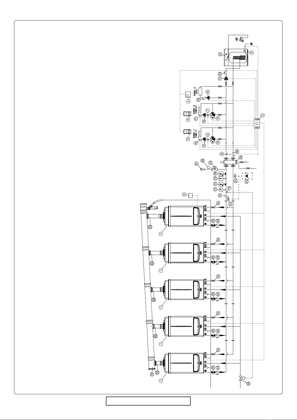
Esempio installativo sicurezze INAIL con caldaie in cascata.
Fig. 5
Legenda:
1 - Generatore
2 - Regolatore di cascata e zone
3 - Gestore di zona
4 - Termostato ambiente modulante
5 - Sonda esterna
6 - Sonda temperatura zona 1 (CMI-1)
7 - Sonda temperatura zona 2 (CMI-2)
8 - Sonda di mandata comune
9 - Sonda temperatura Unità bollitore
10 - Valvola miscelatrice zona 1 (CMI-1)
11 - Valvola miscelatrice zona 2 (CMI-2)
12 - Pompa circuito riscaldamento zona 1 (CMI-1)
13 - Pompa circuito riscaldamento zona 2 (CMI-2)
14 - Pompa circuito diretto zona 3 (CD)
15 - Pompa alimentazione Unità bollitore
16 - Termostato di sicurezza zona 1 (CMI-1)
17 - Termostato di sicurezza zona 2 (CMI-2)
19 - Bulbo valvola intercettazione combustibile
20 - Rubinetto portamanometro omologato INAIL
21 - Termometro omologato INAIL
22 - Pressostato riarmo manuale omologato INAIL
23 - Termostato riarmo manuale omologato INAIL
24 - Attacco per vaso espansione
25 - Vaso espansione
26 - Collettore/miscelatore
27 - Unità bollitore esterna
28 - Valvola intercettazione combustibile
29 - Valvola di ritegno
30 - Filtro impianto raccolta fanghi
31 - Pozzetto portatermometro
32 - Serranda circuito fumi
33 - Tronchetto scarico condensa
34 - Rubinetto di intercettazione impianto
35 - Rubinetto di scarico a tre vie
36 - Riccio ammortizzatore
37 - Manometro omologato INAIL
38 - Pressostato di minima omologato INAIL
Cod. 1.035630 - Rev. ST.000248/000
Installation example of INAIL safety devices with boilers in cascade.
Key:
1 - Generator
2 - Cascade and zone regulator
3 - Zone manager
4 - Modulating room thermostat
5 - External probe
6 - Zone 1 temperature probe (CMI-1)
7 - Zone 2 temperature probe (CMI-2)
8 - Common ow probe
9 - Storage tank unit temperature probe
10 - Zone 1 mixing valve (CMI-1)
11 - Zone 2 mixing valve (CMI-2)
12 - Zone 1 central heating circuit pump (CMI-1)
13 - Zone 2 central heating circuit pump (CMI-2)
14 - Zone 3 direct circuit pump (CD)
15 - Storage tank unit feeding pump
16 - Zone 1 safety thermostat (CMI-1)
17 - Zone 2 safety thermostat (CMI-2)
19 - Fuel shut-o valve bulb
20 - INAIL-approved pressure gauge-holder cock
21 - INAIL-approved thermometer
22 - INAIL-approved manual rearm pressure switch
23 - INAIL-approved manual rearm thermostat
24 - Attachment for expansion vessel
25 - Expansion vessel
26 - Manifold/mixer
27 - External storage tank unit
28 - Fuel shut-o valve
29 - Non return valve
30 - Slurry collection system lter
31 - Manometer pocket
32 - Flue circuit ue adjusting device
33 - Stub pipe drain trap
34 - System cut-o valve
35 - ree-way draining valve
36 - Damper coil
37 - INAIL-approved pressure gauge
38 - INAIL-approved minimum pressure switch

This manual suits for next models

3

Other Immergas Boiler Supplies manuals

Immergas Victrix Superior KW X User manual

Immergas

Immergas Victrix Superior KW X User manual

Immergas 3.031186 Product manual

Immergas

Immergas 3.031186 Product manual

Immergas VICTRIX PRO V2 User manual

Immergas

Immergas VICTRIX PRO V2 User manual

Immergas VICTRIX PRO 35 V2 SET User manual

Immergas

Immergas VICTRIX PRO 35 V2 SET User manual

Immergas Victrix TT Series Product manual

Immergas

Immergas Victrix TT Series Product manual

Immergas 3.021377 User manual

Immergas

Immergas 3.021377 User manual

Immergas Victrix Pro 35-55 User manual

Immergas

Immergas Victrix Pro 35-55 User manual

Immergas VICTRIX PRO 35 User manual

Immergas

Immergas VICTRIX PRO 35 User manual

Immergas 3.032852 User manual

Immergas

Immergas 3.032852 User manual

Immergas 3.032264 Product manual

Immergas

Immergas 3.032264 Product manual

Immergas VICTRIX SUPERIOR KIT User manual

Immergas

Immergas VICTRIX SUPERIOR KIT User manual

Immergas 3.020934 User manual

Immergas

Immergas 3.020934 User manual

Immergas 3.023960 User manual

Immergas

Immergas 3.023960 User manual

Immergas 3.014083 User manual

Immergas

Immergas 3.014083 User manual

Immergas VICTRIX PRO 35 V2 Setup guide

Immergas

Immergas VICTRIX PRO 35 V2 Setup guide

Immergas 3.020355 User manual

Immergas

Immergas 3.020355 User manual

Immergas 3.030323 User manual

Immergas

Immergas 3.030323 User manual

Immergas 3.015266 User manual

Immergas

Immergas 3.015266 User manual

Immergas 3.021378 User manual

Immergas

Immergas 3.021378 User manual

Immergas 3.018911 User manual

Immergas

Immergas 3.018911 User manual

Immergas 3.026302 User manual

Immergas

Immergas 3.026302 User manual

Immergas 3.012944 User manual

Immergas

Immergas 3.012944 User manual

Immergas 3.031483 Product manual

Immergas

Immergas 3.031483 Product manual

Immergas VICTRIX PRO 35 V2 SET User manual

Immergas

Immergas VICTRIX PRO 35 V2 SET User manual

Popular Boiler Supplies manuals by other brands

Field Controls SWGII-5 manual

Field Controls

Field Controls SWGII-5 manual

TriangleTube PTRKIT304 installation instructions

TriangleTube

TriangleTube PTRKIT304 installation instructions

Crown Boiler AM4 installation instructions

Crown Boiler

Crown Boiler AM4 installation instructions

Beretta B23 manual

Beretta

Beretta B23 manual

CleaverBrooks Hawk 1000 Operation manual

CleaverBrooks

CleaverBrooks Hawk 1000 Operation manual

Taco LTA-2 instruction sheet

Taco

Taco LTA-2 instruction sheet

TriangleTube PSSTND02 instructions

TriangleTube

TriangleTube PSSTND02 instructions

KOM-STER TIGRA manual

KOM-STER

KOM-STER TIGRA manual

TiEmme 5535PF Instruction leaflet

TiEmme

TiEmme 5535PF Instruction leaflet

Detandt-Simon 200 Instructions for use and maintenance

Detandt-Simon

Detandt-Simon 200 Instructions for use and maintenance

eta eHACK operating instructions

eta

eta eHACK operating instructions

Bryan Boilers B-26S-D brochure

Bryan Boilers

Bryan Boilers B-26S-D brochure

manuals.online logo
manuals.online logoBrands
  • About & Mission
  • Contact us
  • Privacy Policy
  • Terms and Conditions

Copyright 2025 Manuals.Online. All Rights Reserved.