QHT Direct Vent DVF-4 Rigid User manual

WARNING
If the information in this manual is not followed exactly, a fire
or explosion may result causing property damage, personal
injury or loss of life.
Danger
WHAT TO DO IF YOU SMELL GAS:
• Do not try to light any appliance
• Do not touch any electric switch; do not use any phone in your
building
• Immediately call your gas supplier from a neighbor’s phone.
Follow the gas supplier’s instructions.
• If you can not reach your gas supplier call the fire department
• Installation and service must be performed by a qualified
licensed installer, service agency or the gas supplier.
Distributed By:
QHT, INC.
3560 LAFAYETTE ROAD
BLDG. 2, UNIT A
PORTSMOUTH, NH 03801
PHONE: 603-334-6400
FAX: 603-334-6401
REV. 07/19/2022
DIRECT VENT ADDENDUM
FOR THE FOLLOWING:
BIASI B10 SERIES BOILERS
SAINT ROCH UNIVERSAL BOILERS
Installation Manual For The Following Kits:
DVF-4 Rigid Kit for Bio, #2 Fuel Oil and Gas
DVO Flexible Kit for Bio, #2 Fuel Oil

TABLE OF CONTENTS
Important Information and Warnings 1,2
Homeowner Information For Gas 3
General Information 1 3
Installation Clearances 2 4
Section Page
DVO Flexible Vent Kit and Installation 3 5
DVO Termination Installation 3.1 6
DVO Termination Connection 3.2 7
DVO Joint Assembly 3.3 8
DVO Appliance Connection 3.4 8
DVO Flexible Vent Kit (Oil Only)
DVF-4 Rigid Vent Kit (Gas or Oil)
DVF-4 Rigid Vent Kit and Installation 4 9
DVF-4 Installation of Make-Up Air 4.1 10
DVF-4 Installation of Exhaust/Termination 4.2 10
DVF-4 Joint Assembly 3.3 8
DVF-4 Appliance Connection 3.4 8
Installation of Post Purge Limit 5 11
Burner Setup 6 12
Oil Burner Setup for Biasi 6.1 13
Oil Burner Setup for Saint Roch 6.2 13
Gas Burner Setup for Biasi 6.3 14
Gas Burner Setup for Saint Roch 6.4 14
Gas Line Piping 7 15
Wiring-Oil Burners 8 16
Wiring- Gas Burners 9 17
System Start-Up 10 18
Commissioning 11 19
Maintenance 12 19
Installer Notes 13 20-21

1
IMPORTANT INFORMATION
Please read this page carefully.
ALL BOILERS MUST BE INSTALLED IN ACCORDANCE WITH NATIONAL, STATE AND LOCAL
PLUMBING, HEATING AND ELECTRICAL CODES AND ORDINANCES, AS WELL AS THE
REGULATIONS OF THE SERVING ELECTRICAL, WATER AND GAS UTILITIES.
All systems should be designed by competent licensed heating contractors, and only
persons knowledgeable in the layout and installation of heating systems should attempt
the installation of the B10 boiler. It is the responsibility of the installing contractor to see
that all controls are correctly installed and operating properly when the installation is
completed.
Do not burn volatile garbage, gasoline, naphtha or other flammable liquids other than
No. 2 fuel oil. All flammable liquids (especially gasoline), chemicals, rags, paper, wood
scraps, debris, etc., should be kept away from the boiler at all times. Keep the boiler area
clean and free of all fire hazards.
Please read the literature and warranties supplied by the manufacturers of the various
accessory equipment. This equipment is warranted by the respective manufacturers,
not by Quincy Hydronic Technology, Inc. Each piece of equipment must be installed and
used according to the recommendations of the manufacturer.
Codes and Regulations:
Installation of the boiler, burner, oil tank and related equipment must conform to
national, state and local regulating agencies and codes applicable to the instal-
lation of the equipment. In the absence of local requirements, the following codes
apply:
A. NFPA - #31 Installation of Oil Burning Equipment
B. NFPA - #70 National Electric Code
C. NFPA - #211 Chimneys and Vents
D. ANSI - #Z223.1 National Fuel Gas Code
E. ANSI - Domestic Gas Conversion Burner
F. CAN/CGA - B149 Installation Codes
G. ANSI - CSD-1
H. CSA -C22.1 Canadian Electrical Code, Part1
The above codes are available from:
National Fire Protection Association (NFPA)
Battery March Park
Quincy, MA 02269
http://www.nfpa.org
CSA International
8501 East Pleasant Valley Road
Cleveland, OH 44134
http://www.csa-international.org

2
Any appliance that burns natural gas, propane gas, fuel oil, or coal is capable of producing
carbon monoxide (CO). Carbon monoxide (CO) is a gas which is odorless, colorless and
tasteless but is very toxic. CO is lighter than air and thus may travel throughout the building.
BRIEF EXPOSURE TO HIGH CONCENTRATIONS OF CO, OR PROLONGED EXPOSURE TO LESSER AMOUNTS
OF CO MAY RESULT IN CARBON MONOXIDE POISONING. EXPOSURE CAN BE FATAL AND EXPOSURE
TO HIGH CONCENTRATIONS MAY RESULT IN THE SUDDEN ONSET OF SYMPTOMS INCLUDING
UNCONSCIOUSNESS.
Symptoms of CO poisoning include the following:
dizziness vision problems shortness of breath
headache loss of muscle control unclear thinking
nausea weakness unconsciousness
The symptoms of CO poisoning are often confused with those of influenza, and the highest
incidence of poisoning occurs at the onset of cold weather or during flu season. A victim may
not experience any symptoms, only one symptom, or a few symptoms. Suspect the presence of
carbon monoxide if symptoms tend to disappear when you leave your home.
The following signs may indicate the presence of carbon monoxide:
IF ANY OF THE SYMPTOMS OCCUR, OR IF ANY OF THE SIGNS OF CARBON MONOXIDE ARE PRESENT,
VACATE THE PREMISES IMMEDIATELY AND CONTACT A QUALIFIED HEATING SERVICE COMPANY, THE
GAS COMPANY OR THE FIRE DEPARTMENT.
ONLY QUALIFIED, LICENSED SERVICE CONTRACTORS SHOULD PERFORM WORK ON YOUR B10 BOILER.
WARNING
• Hot gasses from appliance, venting system pipes or chimney, escaping into
the living space.
• Flames coming out around the appliance.
• Yellow colored flames in the appliance.
• Stale or smelly air.
• The presence of soot or carbon in or around the appliance.
• Very high unexplained humidity inside the building.

3
1. General Information
HOMEOWNER INFORMATION FOR GAS
TO START UP THE APPLIANCE
1. STOP! Read the safety information on the side of the boiler. DO NOT START THE BOILER UNLESS
ALL CLEANOUT DOORS ARE SECURED AND SEALED. (Skip to step 9 for oil burning boilers)
2. Set thermostat to lowest setting
3. Turn off all electric power to the appliance
4. Do not attempt to light the burner by hand
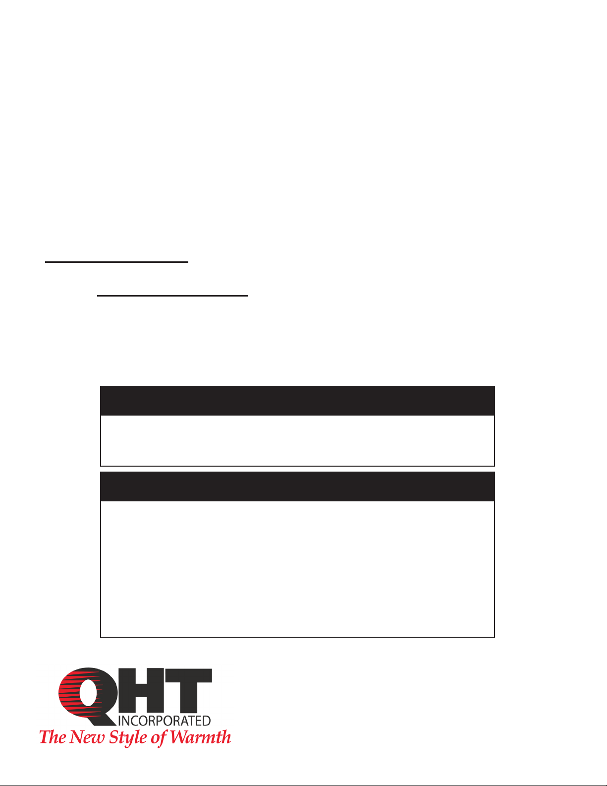
5. Turn the manual shut off on the combination gas valve clockwise to
the off position.
6. Wait five minutes to clear out any gas. Then smell for gas, including
near the floor.
If you smell gas, STOP!
• Do not try to light any appliance
• Do not touch any electric switch; do not use any phone in your building
• Immediately call your gas supplier from a neighbor’s phone. Follow the gas supplier’s
instructions.
• If you can not reach your gas supplier call the fire department
7. If you don’t smell gas, go to the next step.
8. Return the manual valve on the combination gas valve to the on position by reversing
step “5”.
9. Turn on all electric power to the appliance.
10. Set thermostat to the desired setting.
11. If the burner fails to light you may press the reset button once. If the appliance will not
operate, follow the instructions “To Turn Off Gas To Appliance” and call your service technician
or gas supplier. DO NOT ATTEMPT TO START THE BURNER WHEN EXCESS GAS HAS ACCUMULATED,
WHEN THE UNIT IS FULL OF VAPOR, OR WHEN THE COMBUSTION CHAMBER IS VERY HOT.
NOTE: ALWAYS KEEP THE MANUAL FUEL SUPPLY VALVE SHUT OFF IF THE BURNER IS SHUT DOWN FOR
AN EXTENDED PERIOD OF TIME.
TO TURN OFF GAS APPLIANCE
Set the thermostat to the lowest setting.
Turn off electric power to the appliance if service is to be performed.
Turn the gas control valve to the off position.
The QHT Direct Vent components have been designed and packaged so that the Biasi
B-10 boilers, Saint Roch UNIVERSAL boilers can be directly vented to the outside. Properly
maintained, these boiler systems are unsurpassed in efficiency and will provide years of
trouble-free operation.
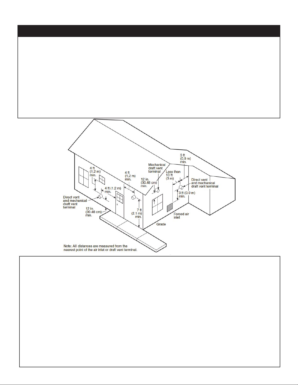
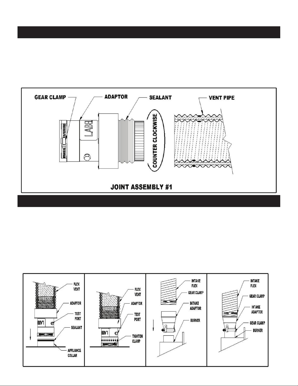
In addition to the standard Biasi or Saint Roch boiler package, the Direct Vent Package
is supplied with a kit containing the standard make-up air and appropriate exhaust system
piping and hoods for your application. The last piece of the complete package is a direct vent
specific burner.
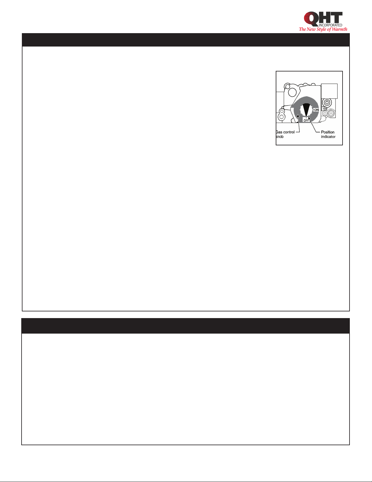
The Direct Vent Systems are a non-powered positive pressure vent hood system for gas
or oil fired appliances that provides an outlet for exhaust gases and an intake for combustion
air. The hood is designed to direct the hot exhaust gases away from the structure without the
aid of a motorized fan. All of the internal parts in contact with the flue gases are made from
corrosion resistant stainless steel.

4
Boilers in rooms shall be installed with the clearances from combustible materials not less than
indicated below. Combustible materials are those made of or surfaced with wood, compressed
paper, plant fibers, plastics, or other material that will ignite and burn, whether flame proofed or
not, or whether plastered or not.
The boiler must not be installed on combustible flooring. The boiler is approved for installation on
non combustible flooring only. The boiler must not be installed on carpeting or vinyl flooring.
2. Installation Clearances
Minimum clearances to combustible construction are as follows:
TOP-24 IN. FRONT-12 IN.
FLUE CONNECTOR DOUBLE WALL DIRECT VENT PIPING – 2”
REAR-2 IN. SIDES-2 IN.
Consult NFPA-31 for construction techniques where the above minimum clearances cannot be
obtained. Recommended clearances for servicing can be found in the boiler manual.
The Exhaust Hood must be installed on the leeward side of house and conform to the following guidelines:
1. The Vent hood shall be installed 12” above ground level or 12” above nominal snow level of the
region of the installation, which ever is higher.
2. The Vent hood shall not be less than 3 feet above any forced air inlet to the house.
3. The Vent hood shall not be less than 4 feet below, 4 feet horizontally, or 1 foot above any door,
window or gravity inlet into any building.
4. The Vent hood shall not be less than 3 feet from any obstruction above the hood.
5. The Vent hood shall not be less than 3 feet from any obstructions horizontally in all directions.
6. The Vent hood shall not be less than 2 feet from an adjacent building.
7. The Vent hood shall be not less than 7 feet above grade when located adjacent to public
walkway.
8. The Vent hood shall be located so that flue gasses are not directed to jeopardize people,
overheat combustible structures, materials or enter buildings.
9. Minimum of 4’ horizontal clearance from electric meters, gas meters, regulators and relief
equipment.
10. All joints in system are to be sealed to prevent leakage of products of combustion in the building.
11. Avoid installing exhaust hood on North, West, or prevailing wind side of the house.

5
# Description Part #
1 4” Tee with VRV D-VRV-4
2 4”x10’ Alumn Flex Duct D-1TLXXX0410
3 6”x 4” Boiler Adapter D-2OILCON64IP
4 4” x 90 Elbow D-
# Description Part #
5 4” Concentric
Termination Hood D-2OILTRM404
6 RTV High-Temp Sealant D-2SILRRTV106X
3. DVO Flexible Vent Kit and Installation
Vent Installation:
1. Vent Pipe bend radius is 12” minimum
2. Support vent pipe with metal strapping every 36”
3. Maximum wall thickness is 14”. Call Z-Flex for recommendations on thicker walls
4. System is not designed for common venting. Use for single boiler only.
5. Appliance adaptor test port is included for combustion test for proper burner
adjustment.
This kit can be used with: Bio and #2 Oil Fuels

6
3.1 DVO Termination Installation
Termination Installation
1. Determine proper location for termination.
2. Cut an 8-1/2” hole through the wall.
3. Pull apart the inner and outer termination sections
4. From outside the building, insert the outer section through the wall until it rests against
the wall. Position the outer section so that the air intake is on the bottom. Secure to
outer wall using four screws. Seal with a weather proof sealant around the edge to
avoid water from entering.
5. From the inside, slide the inner wall plate over the outer section and secure it to the
wall with four screws.

7
3.2 DVO Termination Connection
Termination Connection
1. Slide the terminal inner section over the flexible vent pipe.
2. Attach the adaptor as per the joint assembly instructions.
3. Apply a bead of sealant around the flue collar and slide on adaptor and tighten gear
clamp.
4. Seal the seam on the adaptor.
5. Slide the terminal inner section over the terminal outer section and secure by
tightening the gear clamp.
6. Stretch the intake flex to the desired length and slide over intake collar and secure by
tightening the gear clamp.
7. Seal the gap between the vent pipe and the terminal inner section with silicone
sealant.

8
JOINT ASSEMBLY
1. Apply Sealant to “threaded” end of the vent adaptor.
2. Insert the threaded end into the vent pipe. Screw the adaptor into the vent pipe in a
counter clockwise direction. The adaptor should be inserted fully until it is tight. If it
does not completely screw into the vent, unscrew and repeat.
3. Tighten the gear clamp on to the outer sleeve to complete the joint assembly.
3.3 DVO Joint Assembly
APPLIANCE CONNECTION
1. Connect the appliance adapter to the appliance collas as per joint assembly.
2. Apply Sealant around the appliance flue collar.
3. Slde the appliance adapter over the flue collar.
4. Tighten the gear clamp around collar.
5. Install the burner air adapter. Tighten integral clamp.
6. Put the gear clamp over the intake flex and slide flex over large end of adapter.
Tighten clamp.
7. Install Vacuum relief damper.
3.4 DVO Appliance Connection

9
Air Boot
Exhaust
Combustion
Air
DVF
2” X 2” Frame
Direct Vent
System
Terminal
Vacuum Relief Valve
Typical Installation
# Description Part #
1 4” Tee with VRV D-VRV-4
2 4”x8’ Alumn Flex Duct D-4”ALUFLEX
3 6”x 4” Boiler Adapter D-400312
4 4”x 24” Pipe D-4PVP-24
5 4” x 90 Elbow D-4PVP-E90
# Description Part #
6 4” x 36” Pipe D-4PVP-36
7 4” Concentric
Termination Hood D-400300
8 4” x 18” Pipe Extension D-4PVP-18A
The DVF System must be installed where provisions do not exist for the ducting of combustion
products to the outside. The direct vent connector shall not pass through any floor or ceiling. The
burner exhaust must be ducted directly to the vent hood through listed exhaust pipes provided. The
exhaust pipe throughout it's entire length must be readily accessible for inspection, cleaning and
replacement.
The venting system should be installed and supported in accordance with the National Fuel Gas
Code, ANSI Z223.1, CAN/CGA B149 or in accordance with any local codes.
1
2
3
45
6 7
8
4. DVF-4 Rigid Vent Kit and Installation
This kit can be used with: Bio, #2 Oil, LP & Propane Fuels

10
Installation of DVF Make-up Air:
1. Use 4 inch diameter flex pipe that is provided in the kit or a comparable single wall metal pipe.
The maximum allowable length of intake pipe is twenty feet not including elbows.
2. Begin installing the 4” tee to the burner (Riello requires the supplied 3” to 4” increaser to be
installed first). Secure all joints on the intake with three screws each.
3. Install the supplied vacuum relief damper in the branch of the tee making sure that it is
mounted with all labeling right side up and perfectly horizontal.
4. In the last run leg of the tee install the aluminum flex pipe.
5. Finally attach the other end of the flex pipe to the intake port on the concentric hood.
6. Inspect the intake system and make sure all connections are secure and then seal each joint
with silicone or aluminum tape.
4.1 DVF-4 Installation of Make-Up Air
Installation of DVF Exhaust:
1. Begin by locating a suitable location for the exhaust to breech the wall. This location should
be at least 12” above ground level or the expected snow level, and on the leeward side of the
house. Consult page 6 for required distances from windows, doors, etc. The hood location
must also allow for a upward slope of a 1/4” per foot for the exhaust piping.
2. Once the hood location has been determined, cut a 8” hole for a non combustible wall, or a
9” hole for a combustible wall. Using 2” X 2”, Frame a box around the hole on the outside of
the house so the flange is mounted away from the siding. Attach the hood to the outside
of the house using appropriate screws to support the hood. Use one screw through each of
the predrilled holes on the trim plate of the hood. Do not drill or screw through the hood at
all.
3. Once the hood is secure, mock up the rest of the vent kit. Start by fitting the boiler adapter
onto the boiler and securing it in place with the locking band on the adapter. Install the rest
of the vent sections that are required to complete your job. Connect the next piece of pipe
by pushing the female end of the pipe over the male end of the boiler adapter. Once the
pipe is fully seated, twist the female end clockwise until the locking mechanism is engaged.
Do not screw into the pipe or add sealant to the pipe as this could compromise the factory
seal. Continue in this way until the entire kit is complete from the boiler to the vent hood. It
is allowable to add extra sections of pipe to the vent kit up to 20 equivalent feet. Each 90
degree elbow is 3 equivalent feet and each 45 degree elbow is 1.5 equivalent feet.
4. Once you are satisfied with the fit of the exhaust, make sure that the vent pipe is properly
supported every three feet with a upward slope to the hood of 1/4” every foot.
4.2 DVF-4 Installation of Exhaust / Termination

11
5. Installation of Post Purge Safety Limit
The electricity to the boiler shall come from a dedicated breaker in the electric service
box. A service switch should be mounted on the side of the boiler so the burner technician can
service the burner and controls. The electrical wiring should be routed so as not to interfere
with normal servicing of the boiler. Wiring done in the field between devices not attached to
boiler shall conform with the temperature limitations for type T wire (63F/35C) or other specified
wire as applicable when installed in accordance to manufacturer's instructions and wiring
diagrams.
If an external electrical source is utilized, the boiler, when installed, must be electrically
bonded to ground in accordance with the requirements of the authority having jurisdiction
or , in the absence of such requirements, with the National Electrical Code, ANSI/NFPA 70 or
Canadian Electrical Code Part I,CSA C22.1, Electrical Code.
The Post Purge Immersion Limit is installed to ensure that if the boiler exceeds 220° F, all
power is disconnected to the burner. The Limit should be mounted on the supply side of the
boiler into the supplied tee. To wire the post purge Limit please refer to the schematics for your
specific burner on the following pages.
Note:
Use one of these
3/4 tappings for the
immersion sensor.
Use supplied
3/4x 1/2 bushing.
Note:
Install immersion
sensor in the
supplied tee.
Supplied high limit
immersion sensor MUST
be installed on all direct
vent applications
See wiring diagrams
on pg. 19-20 for correct
wiring.
Saint Roch Universal Boiler Biasi B10 Boiler

12
6. Burner Setup
Good, reliable operation with a minimum of service, starts with attention to the small
details:
Oil:
1. Setting the nozzle position and electrodes to the manufactures specs using the
manufacturer's gauges.
2. Installing a quality micron filter at the burner.(replace old oil lines and clear sludge)
3. Making careful/tight flare connections, without couplings, on oil suction line.
4. Checking fuel pump pressure is set to specs on following page.
5. Checking draft at the breeching to insure it is adequate to overcome flue gas
resistance. (-.02 to –.04 in. w.c.)
6. Setting the air band properly with well maintained instruments. A good target is 12%
to 12.5% of (CO2).
7. To achieve the rated efficiency level the CO2 should be set to 12.5% CO2.
To ensure proper burner setup, gauges should be used to check things such as the
pump pressure, CO2 levels, CO levels, etc…
Gas:
1. Checking the electrode, orifice size, and flame rod settings against manufacturer’s
specs to insure proper operation.
2. Installing properly sized gas piping according to BTU input required and length of gas
line run.
3. Making sure there is proper manifold pressure before and after the gas valve using
a calibrated manometer.
4. Checking draft at the breeching to insure it is adequate to overcome flue gas
resistance. (-.02 to –.04 in. w.c.)
5. Setting the air band properly with well maintained instruments. A good target is 9.5%
to 10.0% of (CO2) for natural gas, or 11.0% to 11.5% of (CO2) for LP gas.
CUT INSULATION IN BLAST
TUBE OPENING TO 4.25"
TO ACCEPT CARLIN BLAST
TUBE.
On BIASI B10 Boilers:
TRIM INSULATION IN
BOILER DOOR OPENING
TO 4.25” FOR BECKETT AND
CARLIN EZ BLAST TUBE.

13
BURNER MANUFACTURER: BECKETT
Boiler Model: B10/4 B10/5
Burner Model: NX
(NEC1104) NX
(NEC1105)
Firing Rate: .78 1.06
Insertion Depth: 6” 6”
Nozzle: .65X60 .75X60
Spray Pattern: B B
Pump Pressure: 180 psi 180 psi
Head Type: NX90LB NX90LB
Head Position/Air Shutter 3.00 4
Air Band: N/A N/A
BURNER MANUFACTURER: RIELLO
B10/3 B10/4 B10/5 B10/6
40 BF3 40 BF3 40 BF5 40 BF5
.51 .78 1.06 1.33
3.5” 3.0” 3.0” 3.0”
.50X80 .65X80 .85X60 1.00X60
W W W W
180 psi 175 psi 150 psi 175 psi
0 1 1 3
3.2 4.7 3.4 5
BURNER MANUFACTURER: CARLIN
Boiler Model: B10/3 B10/4 B10/5 B10/6
Burner Model: EZ-Select EZ-Select EZ-Select EZ-Select
Firing Rate: .50 .78 1.06 1.33
Insertion Depth: 3.0” 3.0” 3.0” 3.0”
Nozzle: .40x45 .65X70 .85X60 1.00X60
Spray Pattern: A A A B
Pump Pressure: 155 psi 150 psi 150 psi 160 psi
Head Setting/Bar:
(Turbulator): .50 .60/.65 .85/1.00 .85/1.00
Air Gate: .50 .75 1 1.2
6.1 Oil Burner Setup For B10 Boilers
6.2 Oil Burner Setup For SRU Boilers
BURNER MANUFACTURER:
CARLIN
Boiler Model: SRU30 SRU40
Burner Model: EZ-97550J EZ-97550J
Firing Rate: 1.00 1.25
Insertion Depth: 4.5” 4.5”
Nozzle: .85X70 1.00X70
Spray Pattern: B B
Pump Pressure: 150 psi 155 psi
Head/Bar: 2 3
Air Gate: 40% 45%
BURNER MANUFACTURER:
RIELLO
Boiler Model: SRU30 SRU40
Burner Model: TBD TBD
Firing Rate:
Insertion Depth:
Nozzle:
Spray Pattern:
Pump Pressure:
Head/Bar:
Air Gate:

14
6.3 Gas Burner Setup For Biasi
This page is only for boilers using a gas burner. If an oil burner is being used,
please refer to page 18 for the proper setup of the burner.
BURNER MANUFACTURER: CARLIN
Boiler Model: B10/3 B10/4 B10/5 B10/6
Burner Model: EZ-GAS EZ-GAS EZ-GAS EZ-GAS
Input (MBH): 80 110 140 175
Fuel Type: Nat LP Nat LP Nat LP Nat LP
Orifice: #11
(.191) #25
(.150) #1
(.228) #15
(.180) LET F
(.257) #5
(.206) 5/16”
(.312) 1/4”
(.250)
Manifold Pressure: 3.5” 3.5” 3.5” 3.5” 3.5” 3.5” 3.5” 3.5”
Air Gate: 30% 30% 40% 48% 20% 20% 36% 41%
Note: Consult burner manufacturers manual for gas manifold diagram and controls.
To determine how much gas is coming into the
burner, or to set the gas meter correctly, the
following formula can be used.
The chart to the right can be used to determine
the flow rate depending upon the time per
revolution and the size of the gas meter dial.
Ft3/hr = [3600/(sec. Per rev.)]*(Size of gas meter)
Seconds Per
Revolution
Size of Gas Meter Dial
(Cubic Foot)
.5 1 2
20 90 180 360
25 72 144 288
30 60 120 240
35 51 103 206
40 45 90 180
45 40 80 160
50 36 72 144
55 33 65 131
60 30 60 120
BURNER MANUFACTURER: CARLIN
Boiler Model: SRU-30 SRU-40
Burner Model: EZ-GAS EZ-GAS
Input (MBH): 140 175
Fuel Type: Nat LP Nat LP
Orifice: LET K
(.281) #1
(.228) LET P
(.323) 7/64
(.266)
Manifold Pressure: 3.5” 3.5” 3.5” 3.5”
Air Gate: 28% 25% 45% 55%
6.4 Gas Burner Setup For SRU Boilers

15
7. Gas Line Piping
Gas supply piping is to be sized and installed properly in order to provide a supply of
gas sufficient to meet the maximum demand without undue loss of pressure between
the meter and the boiler. Consult with the National Fuel Gas Code ANSI Z223.1 for
proper sizing of gas piping for various lengths and diameters.
Locate a drop pipe adjacent to, but not in front of the boiler. Locate a tee in the drop
pipe at the same elevation as the gas inlet connection to the boiler. Extend the drop line
with a nipple towards the floor and cap to form a sediment trap. Install a shut off valve
before the tee with sediment trap and a union after the tee before the combination gas
valve.
When installing the boiler, make sure a pipe compound resistant to the action of
liquefied petroleum is used. Check piping for leaks. Always check leaks with a water
and soap solution. DO NOT USE A FLAME FOR CHECKING GAS LEAKS
The boiler and its individual shut-off valve must be disconnected from the gas supply
piping during any pressure testing of that piping at test pressures in excess of 1/2 psi.
To check for gas leaks, use a
gas detector or apply a soap
solution to the joints. DO NOT
USE AN OPEN FLAME!
Manual Shutoff Valve
Height of shutoff valve above ground level to conform to
local codes, if any.
Note: Massachusetts state code requires gas shutoff to be
a tee handled gas cock.
1” X 1” X 3/4” Tee Male Union 3/4” NPT
Burner Gas Train
Pipe Cap
3” MINIMUM
Direction of flow
Pressure Gauge Port
(1/8” NPT plugged)

16
8. Wiring (Oil Burners)
NOTE: All wiring must be done in accordance with applicable state, local and national codes.
Use only copper conductors.

17
9. Wiring (Gas Burners)
NOTE: All wiring must be done in accordance with applicable state, local and national codes.
Use only copper conductors.

18
10. System Start-Up
“For Your Safety Read Before Operating”
WARNING: If you do not follow these instructions exactly, a fire or explosion may result
causing property damage, personal injury or loss of life.
WARNING: Improper installation, adjustment, alteration, service or maintenance can
cause property damage, personal injury or loss of life. Refer to the user’s information
manual provided with this boiler. Installation and service must be performed by a
qualified installer, service agency or the gas supplier
WARNING: If installed as a direct vent boiler, make sure after service that both the vent
intake and exhaust are both properly reinstalled and sealed.
This appliance does not have a pilot. It is equipped with an ignition device which
automatically lights the burner. Do not try to light the burner by hand.
A) BEFORE OPERATING, smell all around the appliance area for gas. Be sure to smell next
to the floor because some gas is heavier than air and will settle on the floor.
WHAT TO DO IF YOU SMELL GAS
• Do not try to light any appliance
• Do not touch any electric switch; do not use any phone in you r building
• Immediately call your gas supplier from a neighbor’s phone. Follow the gas
supplier’s instructions.
• If you can not reach your gas supplier call the fire department
B) Do not use this appliance if any part has been under water. Immediately call a
qualified service technician to inspect the appliance and to replace any part of the
control system and any gas control which has been under water.
OPERATING INSTRUCTIONS:
1. STOP! Read the safety information above.
2. Set thermostat to lowest setting
3. Turn off all electric power to the appliance
4. Do not attempt to light the burner by hand
5. Smell for gas, including near the floor. If you smell gas, STOP! Follow “B” in the safety
information above on this label. If you don’t smell gas, go to the next step.
6. Turn on all electric power to the appliance.
7. Set thermostat to the desired setting.
8. Once the system is lit, inspect the entire installation.
9. Make sure the pressure in the boiler is stable.
10. Test both high limits by lowering their set points below the temperature of the boiler
one at a time. If either aquastat fails to shut the burner down replace it immediately.
11. Simulate a loss of fuel by shutting the oil valve. Once the valve is closed the burner
should go into post –purge and then lockout.
12. Reset the burner before turning the oil back on to simulate ignition failure. After
ignition failure the burner should go through a purge period and then lookout.
13. Open the oil valve and return the burner to operation. While the burner is running,
trip the breaker at the panel, that should disable the burner and all other heating
controls.
14. Once it is determined that the system is operating properly, proceed to tuning up
the burner using the proper instruments. If you do not have any instruments, do not
place this unit in operation until you have a competent burner technician tune up
the burner.
This manual suits for next models
1
Table of contents