manuals.online logo
Brands
  1. Home
  2. •
  3. Brands
  4. •
  5. Immergas
  6. •
  7. Boiler Supplies
  8. •
  9. Immergas 3.026302 User manual

Immergas 3.026302 User manual

IT IE
Cod. 1.038595 - Rev. ST.002374/003
KIT SCHEDA 2 RELÈ
COD. 3.026302
2RELAY BOARD KIT
CODE 3.026302
AVVERTENZE GENERALI.
Tutti i prodotti sono protetti con idoneo imballaggio da trasporto.
Il materiale deve essere immagazzinato in ambienti asciutti ed al
riparo dalle intemperie.
Il presente foglio istruzioni contiene informazioni tecniche relative
all’installazione del kit. Per quanto concerne le altre tematiche corre-
late all’installazione del kit stesso (a titolo esemplicativo: sicurezza
sui luoghi di lavoro, salvaguardia dell’ambiente, prevenzioni degli
infortuni), è necessario rispettare i dettami della normativa vigente
ed i principi della buona tecnica.
L’installazione o il montaggio improprio dell’apparecchio e/o dei
componenti, accessori, kit e dispositivi potrebbe dare luogo a proble-
matiche non prevedibili a priori nei confronti di persone, animali,
cose. Leggere attentamente le istruzioni a corredo del prodotto per
una corretta installazione dello stesso.
L’installazione e la manutenzione devono essere eettuate in ottem-
peranza alle normative vigenti, secondo le istruzioni del costruttore e
da parte di personale abilitato nonché professionalmente qualicato,
intendendo per tale quello avente specica competenza tecnica nel
settore degli impianti, come previsto dalla Legge.
DESCRIZIONE DEL PRODOTTO.
Il kit in oggetto è predisposto per funzionare su vari modelli di
apparecchi, di seguito vengono riportate le varie soluzioni di
installazione.
- Kit ricambio: la presente scheda deve essere sostituita a quella
danneggiata presente sull’apparecchio.
- Kit optional: la presente scheda permette di ampliare le caratte-
ristiche di funzionamento dell’apparecchio mediante l’ausilio di
due contatti puliti. Installare la scheda all’interno del cruscotto
come descritto nella pagina successiva e far riferimento al
relativo libretto istruzioni dell’apparecchio per il collegamento
elettrico.
COMPOSIZIONE KIT.
Quantità Riferimento
(Fig. 1) Descrizione
1 2 Scheda 2 relè
2 6 Viti ssaggio scheda
1 - Cablaggio di collegamento
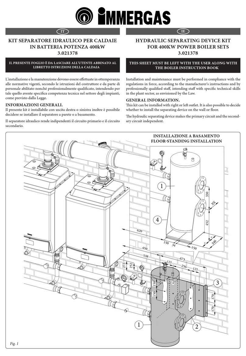
GENERAL WARNINGS.
All products are protected with suitable transport packaging.
e material must be stored in dry environments and protected
against weathering.
is instruction manual provides technical information for installing
the kit. As for the other issues related to kit installation (e.g. safety
in the work site, environment protection, injury prevention), it is
necessary to comply with the provisions specied in the regulations
in force and principles of good practice.
Improper installation or assembly of the appliance and/or compo-
nents, accessories, kit and devices can cause unexpected problems
to people, animals and objects. Read the instructions provided with
the product carefully to ensure a proper installation.
Installation and maintenance must be performed in compliance with
the regulations in force, according to the manufacturer's instructions
and by authorised professionally qualied sta, intending sta with
specic technical skills in the plant sector, as envisioned by the Law.
DESCRIPTION OF THE PRODUCT.
e kit in question is able to work on dierent equipment models.
e dierent installation solutions are shown below.
- Spare part kit: this board must replace the damaged one on the
equipment.
- Optional kit: this board allows you to expand the functioning
features of the equipment with the help of two clean contacts.
Install the board inside the control panel as described on the
following page and refer to the corresponding equipment in-
structions manual for the electrical connection.
KIT COMPOSITION.
Quantity Reference
(Fig. 1) Description
1 2 2-relay board
2 6 Board xing screws
1 - Connection wiring
INSTALLAZIONE KIT 2 RELÈ COME OPTIONAL.
- Togliere alimentazione all’apparecchio, smontare la mantellatura
e far basculare il cruscotto come indicato nel relativo libretto
istruzioni.
- Aprire il cruscotto (1) svitando le viti (3) che ssano il coperchio
(2), Prestare attenzione alla corda 4 che supporta il peso del
cruscotto (1), una volta tolto il coperchio sostenere il cruscotto
(1).
- Posizionare la scheda 2 relè (5) posizionandola sui due perni di
sostegno e ssandola con le due viti (6).
- Collegare il cablaggio presente nel kit come rappresentato nello
schema elettrico dell’apparecchio su cui viene montata.
- Collegare quindi il connettore del cablaggio al connettore libero
presente all’interno del cruscotto.
- Richiudere il cruscotto (1), rimontare la mantellatura e ridare
alimentazione all’apparecchio per riportarlo alle normali con-
dizioni di funzionamento.
INSTALLING THE 2RELAY KIT AS AN EXTRA.
- Cut the supply voltage to the equipment, disassemble the ca-
sing and tip the control panel as shown in the corresponding
instructions manual.
- Open the control panel (1) by unscrewing the screws (3) se-
curing the cover (2). Be careful of the rope (4) supporting the
weight of the control panel (1); once the cover is removed, hold
up the control panel (1).
- Position the 2-relay board (5), putting it on the two support
pins and securing it with the two screws (6).
- Connect the wiring in the kit as shown on the wiring diagram

of the equipment onto which it is tted.
- en connect the wiring connector to the free connector inside
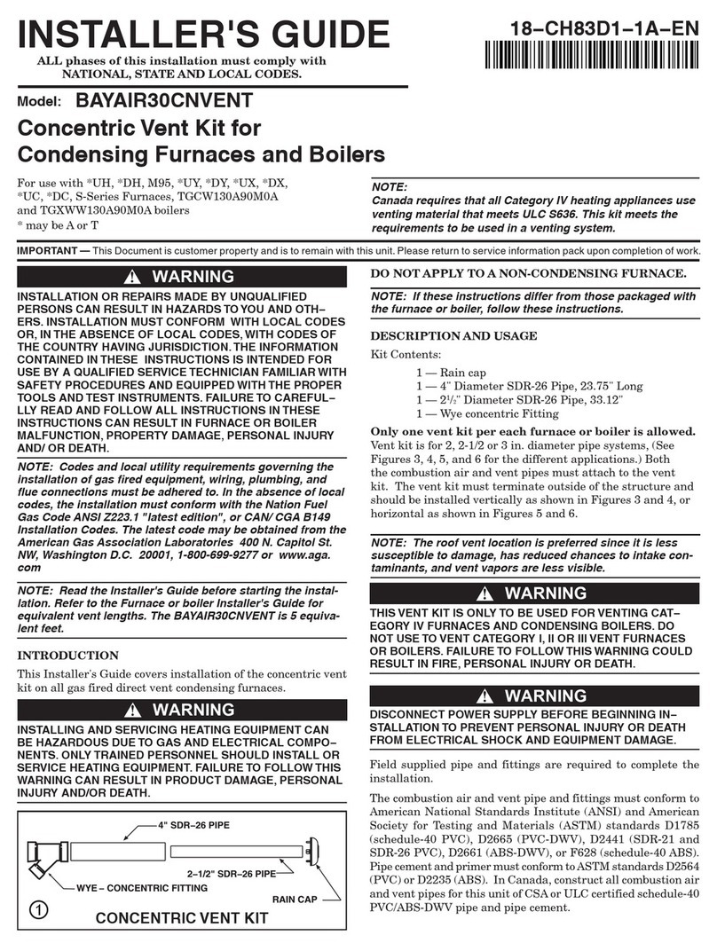
the control panel.
- Close the control panel (1) back up, reassemble the casing and
restore supply voltage to the equipment to bring it back to its

normal operating conditions.

2
1
5
3
3
4
6
Magis Pro - Magis Combo - Magis Combo Plus
1
2
1
5
3
3
4
6
1
Magis Pro V2 - Magis Combo V2 - Magis Combo Plus V2
BK
6
BK
Y6
431
G
2
5
PK
G
G
P
P
PK
G
PK
BK
BK
P
P
P
G
G
A2
A16-2
30-2
A16-1
BK
BK
A19 PK
PK
P
29-1
PK
30-1 29-2
1
1
X32
X31
2
2
X33
4 3 2 1
SCHEMA ELETTRICO WIRING DIAGRAM
Legenda colori:
BK - Nero
BL - Blu
BR - Marrone
G - Verde
GY - Grigio
G/Y - Giallo/Verde
P - Viola
PK - Rosa
R - Rosso
Legenda:
A2 -Scheda regolazione
A16-1-Deumidicatore zona 1 (optional)
A16-2-Deumidicatore zona 2 (optional)
A19 -Scheda due relè (optional)
Colour cable key:
BK - Black
BL - Blue
BR - Brown
G - Green
GY - Grey
P - Purple
PK - Pink
R - Red
Y/G - Yellow/Green
Key:
A2 -Mainboard
A16-1-Zone 1 Dehumidier (optional)
A16-2-Zone 2 Dehumidier (optional)
A19 -Two Relays Board (optional)
Magis Pro - Magis Combo - Magis Combo Plus
Magis Pro V2 - Magis Combo V2 - Magis Combo Plus V2
Legenda colori:
BK - Nero
BL - Blu
BR - Marrone
G - Verde
GY - Grigio
G/Y - Giallo/Verde
P - Viola
PK - Rosa
R - Rosso
Legenda:
A2 -Scheda regolazione
A16-1-Deumidicatore zona 1 (optional)
A16-2-Deumidicatore zona 2 (optional)
A19 -Scheda due relè (optional)
Colour cable key:
BK - Black
BL - Blue
BR - Brown
G - Green
GY - Grey
P - Purple
PK - Pink
R - Red
Y/G - Yellow/Green
Key:
A2 -Mainboard
A16-1-Zone 1 Dehumidier (optional)
A16-2-Zone 2 Dehumidier (optional)
A19 -Two Relays Board (optional)

Other Immergas Boiler Supplies manuals

Immergas 3.015266 User manual

Immergas

Immergas 3.015266 User manual

Immergas 3.031186 Product manual

Immergas

Immergas 3.031186 Product manual

Immergas 3.020355 User manual

Immergas

Immergas 3.020355 User manual

Immergas 3.021377 User manual

Immergas

Immergas 3.021377 User manual

Immergas 3.032264 Product manual

Immergas

Immergas 3.032264 Product manual

Immergas VICTRIX PRO 35 V2 Setup guide

Immergas

Immergas VICTRIX PRO 35 V2 Setup guide

Immergas VICTRIX PRO V2 User manual

Immergas

Immergas VICTRIX PRO V2 User manual

Immergas 3.014083 User manual

Immergas

Immergas 3.014083 User manual

Immergas 3.018911 User manual

Immergas

Immergas 3.018911 User manual

Immergas VICTRIX SUPERIOR KIT User manual

Immergas

Immergas VICTRIX SUPERIOR KIT User manual

Immergas VICTRIX PRO 35 User manual

Immergas

Immergas VICTRIX PRO 35 User manual

Immergas 3.021378 User manual

Immergas

Immergas 3.021378 User manual

Immergas 3.023960 User manual

Immergas

Immergas 3.023960 User manual

Immergas VICTRIX PRO 35 V2 SET User manual

Immergas

Immergas VICTRIX PRO 35 V2 SET User manual

Immergas Victrix TT Series Product manual

Immergas

Immergas Victrix TT Series Product manual

Immergas Victrix Pro 35-55 User manual

Immergas

Immergas Victrix Pro 35-55 User manual

Immergas 3.020934 User manual

Immergas

Immergas 3.020934 User manual

Immergas 3.031483 Product manual

Immergas

Immergas 3.031483 Product manual

Immergas VICTRIX PRO 35 V2 SET User manual

Immergas

Immergas VICTRIX PRO 35 V2 SET User manual

Immergas 3.030323 User manual

Immergas

Immergas 3.030323 User manual

Immergas 3.032852 User manual

Immergas

Immergas 3.032852 User manual

Immergas 3.012944 User manual

Immergas

Immergas 3.012944 User manual

Immergas Victrix Superior KW X User manual

Immergas

Immergas Victrix Superior KW X User manual

Immergas INAIL VICTRIX PRO 80 User manual

Immergas

Immergas INAIL VICTRIX PRO 80 User manual

Popular Boiler Supplies manuals by other brands

Rheem Ruud TRD Technical service bulletin

Rheem

Rheem Ruud TRD Technical service bulletin

IBC P-175 manual

IBC

IBC P-175 manual

Fröling Lambdatronic H 3200 Service manual
Fröling

Fröling Lambdatronic H 3200 Service manual

Grunbeck GENO-Neutra FNH-420-R Operation manual

Grunbeck

Grunbeck GENO-Neutra FNH-420-R Operation manual

LK 816 ThermoKit E Eco instruction manual

LK

LK 816 ThermoKit E Eco instruction manual

AFRISO PrimoTherm KSV 125-3 operating instructions

AFRISO

AFRISO PrimoTherm KSV 125-3 operating instructions

manuals.online logo
manuals.online logoBrands
  • About & Mission
  • Contact us
  • Privacy Policy
  • Terms and Conditions

Copyright 2025 Manuals.Online. All Rights Reserved.