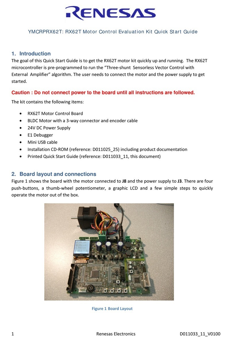
Infineon Technologies XMC4000 Application Kit User manual


Other manuals for XMC4000 Application Kit
3
This manual suits for next models
1
Table of contents
Other Infineon Technologies Microcontroller manuals

Infineon Technologies
Infineon Technologies C166S V2 User manual
Infineon Technologies
Infineon Technologies XMC4000 Application Kit User manual

Infineon Technologies
Infineon Technologies TC1784 User manual

Infineon Technologies
Infineon Technologies XMC4000 Application Kit User manual
Infineon Technologies
Infineon Technologies XMC4500 Relax kit User manual
Infineon Technologies
Infineon Technologies TC1728 User manual
Infineon Technologies
Infineon Technologies XMC4500 series User manual
Infineon Technologies
Infineon Technologies XC800 User manual
Infineon Technologies
Infineon Technologies TriBoard TC2X3 User manual
Infineon Technologies
Infineon Technologies XC164CS-8FF User manual
Infineon Technologies
Infineon Technologies XMC4000 Application Kit User manual
Infineon Technologies
Infineon Technologies CYPRESS Traveo Series User manual
Infineon Technologies
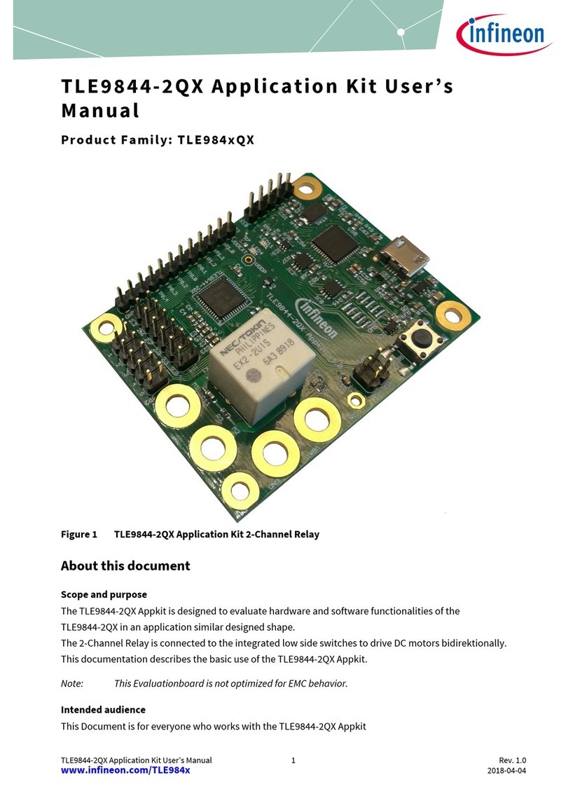
Infineon Technologies TLE9844-2QX User manual
Infineon Technologies
Infineon Technologies XMC1000 User manual
Infineon Technologies
Infineon Technologies XC82x User manual
Popular Microcontroller manuals by other brands
iWave
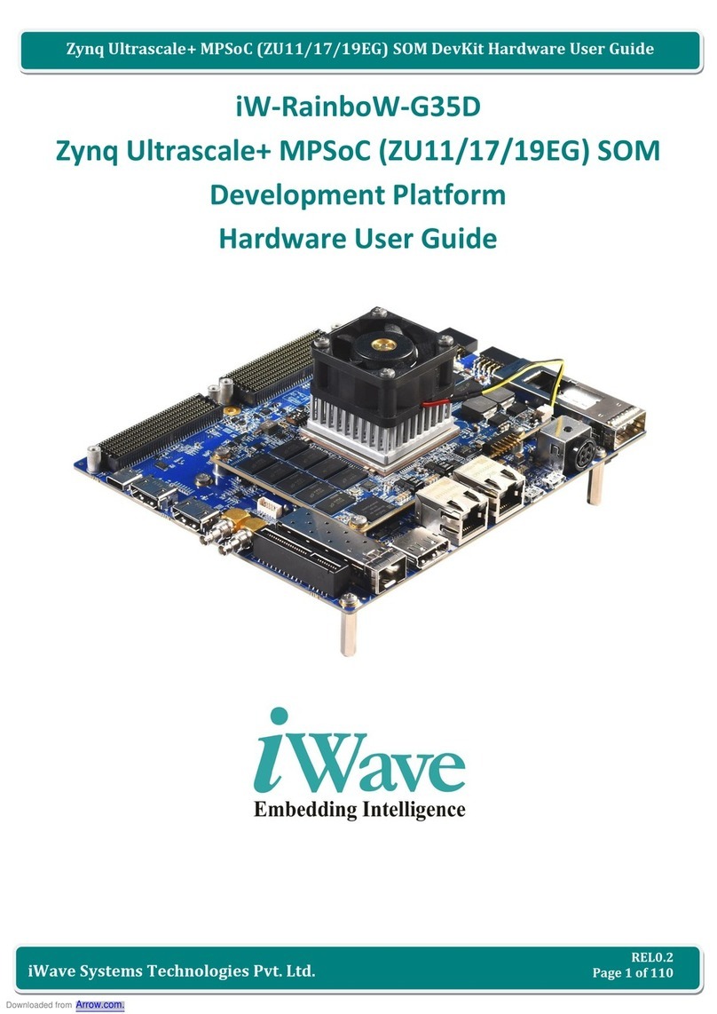
iWave iW-RainboW-G35D Hardware user's guide
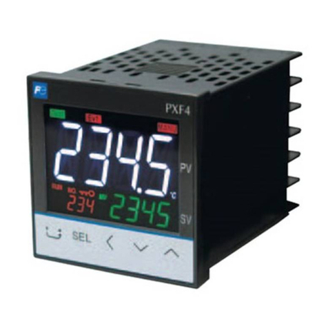
Fuji Electric
Fuji Electric PXF-2 Operation manual
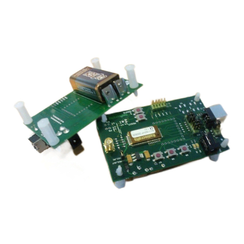
Radiocrafts
Radiocrafts RC HP-DK Series user manual
Freescale Semiconductor
Freescale Semiconductor Flexis Series quick start guide
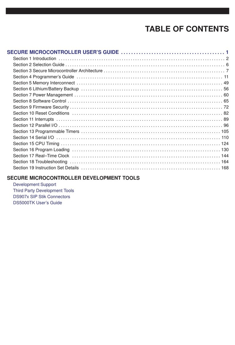
Mitsubishi
Mitsubishi DS907x SIP user guide

Cypress
Cypress S6J3200 Series Guidelines
