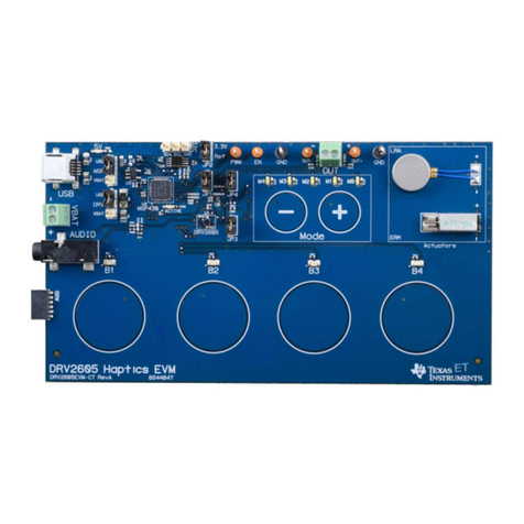
XDP710 evaluation PCBA user guide
Scope and purpose
Setup and evaluation of XP710 printed circuit board assembly (PCBA).
Intended audience
Test engineers.
Table of contents
Table of contents............................................................................................................................ 1
1Introduction .......................................................................................................................... 2
2Hardware and software requirements...................................................................................... 2
3XDP710 evaluation platform.................................................................................................... 3
3.1 Electrical specifications ..........................................................................................................................3
3.2 Block diagram..........................................................................................................................................3
3.3 XDP710 evaluation board schematics....................................................................................................5
3.4 XDP710 evaluation board layout ............................................................................................................7
3.5 XDP710 evaluation board bill of materials...........................................................................................12
3.6 XDP710 evaluation board default settings...........................................................................................14
3.7 Rsns ..........................................................................................................................................................16
3.8 FET board...............................................................................................................................................16
3.8.1 Different FET footprint options on FET board......................................................................................16
3.9 USB007A dongle schematics.................................................................................................................18
4Programming, setup, and turn-on instructions.........................................................................18
4.1 XDP Designer communication setup....................................................................................................19
4.1.1 Check the dongle connection in XDP Designer...............................................................................19
4.1.2 Detecting XDP710-002......................................................................................................................20
4.1.3 Reading and writing registers..........................................................................................................22
4.1.4 Program FET.....................................................................................................................................23
4.1.5 Program Rsns......................................................................................................................................24
4.1.6 Watchdog timer selection................................................................................................................24
4.1.7 Program current sense range (CS_RNG) and start-up current limit (IST)......................................25
4.1.8 Program VIN_UV_FAULT_LIMIT.......................................................................................................25
4.1.9 Program VIN_OV_FAULT_LIMIT.......................................................................................................26
4.1.10 Program VOUT_UV_FAULT_LIMIT ...................................................................................................26
4.2 XDP710 programming under different modes .....................................................................................27
4.2.1 FDM...................................................................................................................................................27
4.2.1.1 FDM (DCM) ........................................................................................................................................27
4.2.1.2 FDM (ACM).........................................................................................................................................28
4.2.2 AADM.................................................................................................................................................28
5Loading configuration file ......................................................................................................30
6Hands-on..............................................................................................................................32
6.1 Example test: UV fault ...........................................................................................................................32
6.2 Programming SOA, OTP, and MTP........................................................................................................33
Revision history.............................................................................................................................35


