Ingeteam Ingerev Garage User manual

Communication accesories in
INGEREV recharging stations
Installation and Operation Manual
Manual de instalación y uso
Manuel d'installation et usage
Manuale d'installazione e uso

ABA2017IQM01_B
01/2018
Ingeteam Power Technology, S.A. - Energy
Avda. Ciudad de la Innovación, 13
31621 SARRIGUREN (Navarra) - Spain
Tel.: +34 948 28 80 00
Fax.: +34 948 28 80 01
e-mail: electricmobility[email protected]
Service Call Center: +34 948 698 715

3
Ingeteam
ABA2017IQM01_B
English EN
Español ES
Français FR
Italiano IT

4
Ingeteam
ABA2017IQM01_B
The copy, distribution or use of this document or of its content requires written authorisation. Any breach thereof will be reported for
damages. All rights reserved including those of patent rights or design registration.
The conformity of the document content with the hardware described has been checked. However, discrepancies may exist. Liability
will not be assumed for total concordance. The information contained in this document is regularly reviewed and it is possible that
there may be changes in subsequent editions. Other functions may be available which are not covered by this document.
This document may be changed.
La copia, circulación o uso de este documento o de su contenido requiere un permiso por escrito. Su incumplimiento será
denunciado por daños y perjuicios. Todos los derechos están reservados, incluyendo aquellos que resulten de derechos de patentes
o registro del diseño.
La correspondencia del contenido del documento con el hardware ha sido comprobada. Sin embargo, pueden existir discrepancias.
No se asume ninguna responsabilidad por la concordancia total. La información que contiene este documento es revisada
regularmente y es posible que se produzcan cambios en siguientes ediciones.
El presente documento es susceptible de ser modificado.
La copie, distribution ou utilisation de ce document ou de son contenu requiert une autorisation écrite. Toute personne ne respectant
pas cette condition sera passible de poursuites. Tous les droits sont réservés, y compris ceux qui découlent des droits de brevets ou
d’enregistrement des conceptions.
La correspondance entre le contenu du document et le matériel a été vérifiée. Il peut toutefois exister des divergences. Aucune
responsabilité de concordance totale n’est assumée. Les informations contenues dans ce document sont régulièrement révisées et il
est possible que des changements surviennent dans les éditions à venir.
Le présent document est susceptible d’être modifié.
Per copiare, condividere o utilizzare il presente documento o il suo contenuto è necessaria un’autorizzazione scritta. Il mancato
rispetto di quest’obbligo sarà perseguito. Tutti i diritti sono riservati, compresi quelli risultanti da diritti di brevetti o dalla registrazione
del progetto.
La corrispondenza del contenuto del presente documento con l’hardware è stata verificata, tuttavia, possono sussistere discrepanze.
Si declina ogni responsabilità relativamente alla concordanza totale. Le informazioni contenute in questo documento sono
regolarmente sottoposte a revisione ed è possibile che siano inserite delle modifiche nelle prossime edizioni.
Questo documento può essere soggetto a modifiche.

5
Contents Ingeteam
Contents
Contents ................................................................................................................................................... 5
1. About this manual.................................................................................................................................. 6
1.1. Scope of application ...................................................................................................................... 6
1.2. Recipients..................................................................................................................................... 6
1.3. Symbols........................................................................................................................................ 6
2. Safety................................................................................................................................................... 7
2.1. Safety conditions ........................................................................................................................... 7
2.2. Personal Protective Equipment (PPE) .............................................................................................. 7
2.3. Waste handling.............................................................................................................................. 8
3. INGEREV GARAGE Wall.......................................................................................................................... 9
3.1. Installation of cable inlets .............................................................................................................. 9
3.2. Local communication ................................................................................................................... 10
3.3. Remote communication................................................................................................................ 11
3.3.1. Remote communication via external modem........................................................................... 11
3.3.2. GPRS/3G remote communication via USB modem .................................................................. 13
4. INGEREV CITY Duo ............................................................................................................................. 17
4.1. Local communication ................................................................................................................... 17
4.2. Remote communication................................................................................................................ 17
4.2.1. Remote communication via external modem........................................................................... 17
4.2.2. GPRS/3G remote communication via USB modem .................................................................. 22
ABA2017IQM01_B - Installation and Operation Manual
EN
ES
FR
IT

6
About this manual
Ingeteam
1. About this manual
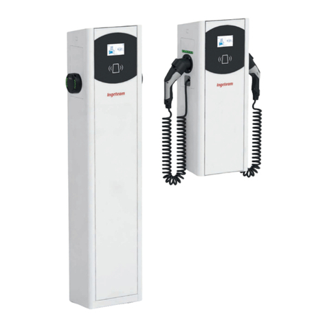
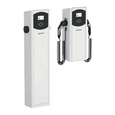
The purpose of this manual is to describe communication in INGEREV charging stations. All the charging stations
can be accessed both locally or remotely, using - for the latter - an external modem located in the installation or a
USB modem if requested upon placing the order.
Configuration and monitoring of all stations is carried out using the specific software provided by Ingeteam.
1.1. Scope of application
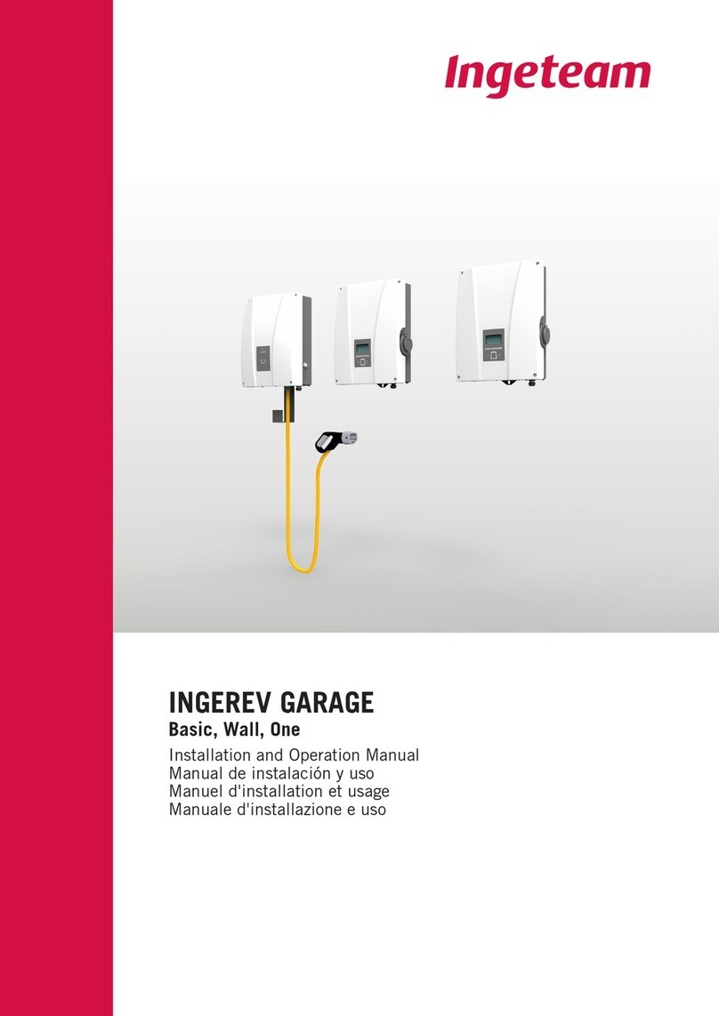
This manual is valid for all the models of the following INGEREV families:
INGEREV GARAGE Wall
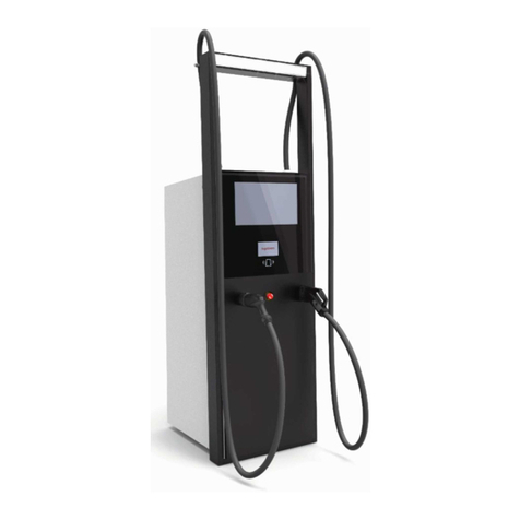
INGEREV CITY Duo
1.2. Recipients
This document is intended for qualified personnel.
The status of qualified personnel referred to in this manual will be, as a minimum, that which meets all the
standards, regulations and laws regarding safety applicable to the tasks of installing and operating all the
components of the installation.
Any operations carried out by personnel not authorized to do so by Ingeteam can lead to the annulment of the
unit's original warranty.
The responsibility for designating qualified personnel will always fall to the company to which the personnel
belong. It is necessary to decide which workers are suitable or not for carrying out specific work to preserve their
safety at the same time as complying with occupational safety legislation.
These companies are responsible for providing appropriate training in electrical equipment to their personnel and
for familiarizing them with the contents of this manual.
1.3. Symbols
Throughout this manual we include warnings to highlight certain information. Relative to the nature of the text,
there are three types of warnings:
Indicates importance.
CAUTION
This indicates a hazard to personnel or the unit.
DANGER
Additional information or references to other parts of the document or documents.
INFO
ABA2017IQM01_B - Installation and Operation Manual

7
Safety Ingeteam
2. Safety
This section describes the safety warnings and the Personal Protective Equipment used in the unit.
2.1. Safety conditions
General warnings
DANGER
Opening the enclosure does not imply there is no voltage inside.
Only qualified personnel may open it, following the instructions in this manual.
CAUTION
The operations described in the manual may be performed only by qualified personnel.
The status of qualified personnel referred to in this manual will be, as a minimum, that which meets all the
standards, regulations and laws regarding safety applicable to the tasks of installing and operating this unit.
The responsibility for designating qualified personnel will always fall to the company to which the personnel
belong. It is necessary to decide which workers are suitable or not for carrying out specific work to preserve their
safety at the same time as complying with occupational safety legislation.
These companies are responsible for providing appropriate training in electrical equipment to their personnel
and for familiarizing them with the contents of this manual.
All applicable safety-related legislation for electrical work must be complied with. Danger of electric shock.
Compliance with the safety instructions set out in this manual or in the suggested legislation does not imply
exemption from other specific standards for the installation, place, country or other circumstances that affect
the inverter.
You must consider the set of conditions listed throughout this document as minimum requirements. It is always
preferable to shut off the main power supply. There may be faults in the installation that cause the unwanted
return of voltage. Danger of electric shock.
According to basic safety standards, the complete unit must be suitable to protect exposed workers against the
risk of direct and indirect contact. In any case the electrical parts of the work equipment must comply with the
provisions of the corresponding specific regulations.
According to basic safety standards, the electrical installation shall not entail a fire or explosion risk. Workers
must be duly protected against the risk of accidents caused by direct or indirect contact. The electrical
installation and protection devices must take into account the voltage, the external conditions and the
competence of persons who have access to parts of the installation.
2.2. Personal Protective Equipment (PPE)
When working on the unit, use the following recommended safety equipment as a minimum.
Name Explanation
Safety footwear In compliance with standard UNE-EN-ISO 20345:2012
Helmet In compliance with standard EN 397:1995
Helmet with face shield In compliance with Standard UNE-EN 166:2002, wherever there are directly
accessible live parts.
Working clothes Close-fitting, non-flammable, 100% cotton
Dielectric gloves In compliance with standard EN 60903:2005
Tools and / or equipment used in live work must have at least Category III-1000 Volts insulation.
Should the country’s regulations demand another kind of personal protection, the recommended equipment should
be appropriately supplemented.
ABA2017IQM01_B - Installation and Operation Manual
EN
ES
FR
IT

8
Safety
Ingeteam
2.3. Waste handling
At the end of the useful life of the printed circuit boards they must be sent to an authorized manager to be
correctly recycled.
ABA2017IQM01_B - Installation and Operation Manual

9
INGEREV GARAGE Wall Ingeteam
3. INGEREV GARAGE Wall
3.1. Installation of cable inlets
In order to install the communication accessories in INGEREV GARAGE Wall charging stations it is necessary to
install packing glands to transfer cables between stations.
Follow the instructions below to install the packing glands:
1. Punch out one of the pre-cut holes from the lower connection plate.
2. Insert the packing gland into the hole and screw the nut.
ABA2017IQM01_B - Installation and Operation Manual
EN
ES
FR
IT

10
INGEREV GARAGE Wall
Ingeteam
3. Thread the cabling through and tighten the packing gland. Leave margin so that the cabling is not tense.
3.2. Local communication
INFO
INGEREV GARAGE Wall charging stations have a local RS-485 data bus with an RJ45 connector that enable
interconnection between the stations. Consult the corresponding installation manual for more information on
this subject.
ABA2017IQM01_B - Installation and Operation Manual

11
INGEREV GARAGE Wall Ingeteam
3.3. Remote communication
3.3.1. Remote communication via external modem
1. Connect the communications card with Ethernet connection to one of the charging stations located at one
end of the installation. This station will act as the first in the communication ring. It can be connected
both with the J15 and J17 connectors, as well as the J16 and J18 connectors.
In this station, remove the end of line jumper from the control card (marked as A in the following figure)
and connect the charging station to the next station of the communication ring (dark gray cable in the
figure below).
A
2. Connect the wiring that joins the control card to the communications card (see the dark gray cable in the
following figure).
Pin Color Signal
1 White/Orange RS-485 B (+)
2 Orange RS-485 A (–)
Connect the modem to the communications card (see the white cable in the figure below).
ABA2017IQM01_B - Installation and Operation Manual
EN
ES
FR
IT
12
INGEREV GARAGE Wall
Ingeteam
The communications card switch (B in the following figure) must have position 3 On.
B
3. Connect the rest of the charging stations according to the following figures:
First station Intermediate station Final station
The jumper of the control card must be removed in all the stations except for the final station on the
communication ring, where it must be installed.
ABA2017IQM01_B - Installation and Operation Manual

13
INGEREV GARAGE Wall Ingeteam
Modem
First station Intermediate station Final stationCommunication ring:
A maximum of 10 units can be interconnected.
3.3.2. GPRS/3G remote communication via USB modem
1. Connect the communications card to one of the charging stations located at one end of the installation in
order to start the communication ring. It can be connected both with the J15 and J17 connectors, as well
as the J16 and J18 connectors.
A
Remove the end of line jumper from the control card and connect the charging station to the next station
of the communication ring (dark gray cable in the previous figure).
ABA2017IQM01_B - Installation and Operation Manual
EN
ES
FR
IT
14
INGEREV GARAGE Wall
Ingeteam
2. Connect the wiring that joins the control card to the communications card (see the dark gray cable in the
following figure).
Pin Color Signal
1 White/Orange RS-485 B (+)
2 Orange RS-485 A (–)
Connect the USB modem to the communications card to obtain the GPRS/3G connection (see the white
cable in the figure below).
On the communications card switch position 3 must be On.
ABA2017IQM01_B - Installation and Operation Manual

15
INGEREV GARAGE Wall Ingeteam
3. Connect the rest of the charging stations as shown in the following figures:
First station Intermediate station Final station
The jumper of the control card must be removed in all the stations except for the final station on the
communication ring, where it must be installed.
First station Intermediate station Final stationCommunication ring:
A maximum of 10 units can be interconnected.
ABA2017IQM01_B - Installation and Operation Manual
EN
ES
FR
IT
16
INGEREV GARAGE Wall
Ingeteam
Antenna for USB modem
Optionally, an exterior antenna can be requested to boost the modem signal. The connection process is shown
below.
1. Punch out the pre-cut hole from the top part of the station.
2. Thread the antenna wiring through the hole and attach the antenna to the station using the nut supplied.
3. Connect the modem antenna cabling.
ABA2017IQM01_B - Installation and Operation Manual

17
INGEREV CITY Duo Ingeteam
4. INGEREV CITY Duo
4.1. Local communication
INFO
These charging stations have a local RS-485 data bus that enables interconnection between the stations.
Consult the corresponding installation manual for more information on this subject.
4.2. Remote communication
4.2.1. Remote communication via external modem
1. The communications cards must be installed in the control card of the first station in the communication
ring. To access the control card, remove the six screws indicated in the following figure and remove the
front cover.
ABA2017IQM01_B - Installation and Operation Manual
EN
ES
FR
IT
18
INGEREV CITY Duo
Ingeteam
2. Connect the communications card with the Ethernet connection on the J15 and J18 connectors of the
control card. The end of line JP1 jumper on the control card in the station where the communications
card is connected must be removed.
J15
J18
A. Jumper JP1 on the control card, uninstalled
B. Communications card
C. Control card on the charging station
A
BC
ABA2017IQM01_B - Installation and Operation Manual

19
INGEREV CITY Duo Ingeteam
3. Disconnect the cable marked D on the following figure.
D
4. Connect the cable marked D on the female RJ45 on the communications card.
D
ABA2017IQM01_B - Installation and Operation Manual
EN
ES
FR
IT
20
INGEREV CITY Duo
Ingeteam
5. Connect the wiring that joins the control card to the communications card (see Cable E, light gray cabling
in the following figure).
E
G
To wire the communications card and control card at the station, you must keep in mind the following
connection positions:
Pin Color Signal
1 White/Orange RS-485 B (+)
2 Orange RS-485 A (–)
The communications card switch (marked as G in the above figure) must have position 3 On.
4. Connect the charging stations that make up the communication ring from the back, as indicated in the
following figures. In the first station, the RJ45 connector on the left is used to start the communication
ring (H) and the connector on the right to connect the modem (I).
HI
First station Intermediate station Final station
ABA2017IQM01_B - Installation and Operation Manual
Other manuals for Ingerev Garage
3
This manual suits for next models
1
Table of contents
Languages:
Other Ingeteam Batteries Charger manuals

Ingeteam
Ingeteam INGEREV RAPID ST Series User manual

Ingeteam
Ingeteam NEO User manual

Ingeteam
Ingeteam INGEREV FUSION Installation manual

Ingeteam
Ingeteam NEO User manual

Ingeteam
Ingeteam INGEREV RAPID 50 Trio User manual

Ingeteam
Ingeteam Ingerev City User manual

Ingeteam
Ingeteam INGEREV FUSION Street FS1MW User manual

Ingeteam
Ingeteam Ingerev Garage User manual

Ingeteam
Ingeteam Ingerev Garage User manual