Ingeteam NEO User manual

NEO / NEO Pro
Installation manual
Manual de instalación
Manuel d’installation
Manuale d’installazione

ABV2013IQM01_
07/2022
Ingeteam Power Technology, S.A. - Energy
Avda. Ciudad de la Innovación, 13
31621 SARRIGUREN (Navarra) - Spain
Tel.: +34 948 28 80 00
Fax.: +34 948 28 80 01
e-mail: electricmobility[email protected]
Service Call Center: +34 948 698 715

ABV2013IQM01_
English EN
Español ES
Français FR
Italiano IT
3
Ingeteam

ABV2013IQM01_
The copy, distribution or use of this document or of its content requires written authorisation. Any breach thereof will be reported for
damages. All rights reserved including those of patent rights or design registration.
The conformity of the document content with the hardware described has been checked. However, discrepancies may exist. Liability
will not be assumed for total concordance. The information contained in this document is regularly reviewed and it is possible that
there may be changes in subsequent editions. Other functions may be available which are not covered by this document.
This document may be changed.
La copia, circulación o uso de este documento o de su contenido requiere un permiso por escrito. Su incumplimiento será
denunciado por daños y perjuicios. Todos los derechos están reservados, incluyendo aquellos que resulten de derechos de patentes
o registro del diseño.
La correspondencia del contenido del documento con el hardware ha sido comprobada. Sin embargo, pueden existir discrepancias.
No se asume ninguna responsabilidad por la concordancia total. La información que contiene este documento es revisada
regularmente y es posible que se produzcan cambios en siguientes ediciones.
El presente documento es susceptible de ser modificado.
La copie, distribution ou utilisation de ce document ou de son contenu requiert une autorisation écrite. Toute personne ne respectant
pas cette condition sera passible de poursuites. Tous les droits sont réservés, y compris ceux qui découlent des droits de brevets ou
d’enregistrement des conceptions.
La correspondance entre le contenu du document et le matériel a été vérifiée. Il peut toutefois exister des divergences. Aucune
responsabilité de concordance totale n’est assumée. Les informations contenues dans ce document sont régulièrement révisées et il
est possible que des changements surviennent dans les éditions à venir.
Le présent document est susceptible d’être modifié.
Per copiare, condividere o utilizzare il presente documento o il suo contenuto è necessaria un’autorizzazione scritta. Il mancato
rispetto di quest’obbligo sarà perseguito. Tutti i diritti sono riservati, compresi quelli risultanti da diritti di brevetti o dalla registrazione
del progetto.
La corrispondenza del contenuto del presente documento con l’hardware è stata verificata, tuttavia, possono sussistere discrepanze.
Si declina ogni responsabilità relativamente alla concordanza totale. Le informazioni contenute in questo documento sono
regolarmente sottoposte a revisione ed è possibile che siano inserite delle modifiche nelle prossime edizioni.
Questo documento può essere soggetto a modifiche.
4
Ingeteam

ABV2013IQM01_ - Installation manual
EN
ES
FR
IT
5
Contents Ingeteam
Contents
Contents ................................................................................................................................................... 5
1. Welcome ............................................................................................................................................... 6
1.1. About this manual ......................................................................................................................... 6
1.2. Warranty ....................................................................................................................................... 6
1.3. Safety measures ............................................................................................................................ 6
2. Before starting....................................................................................................................................... 7
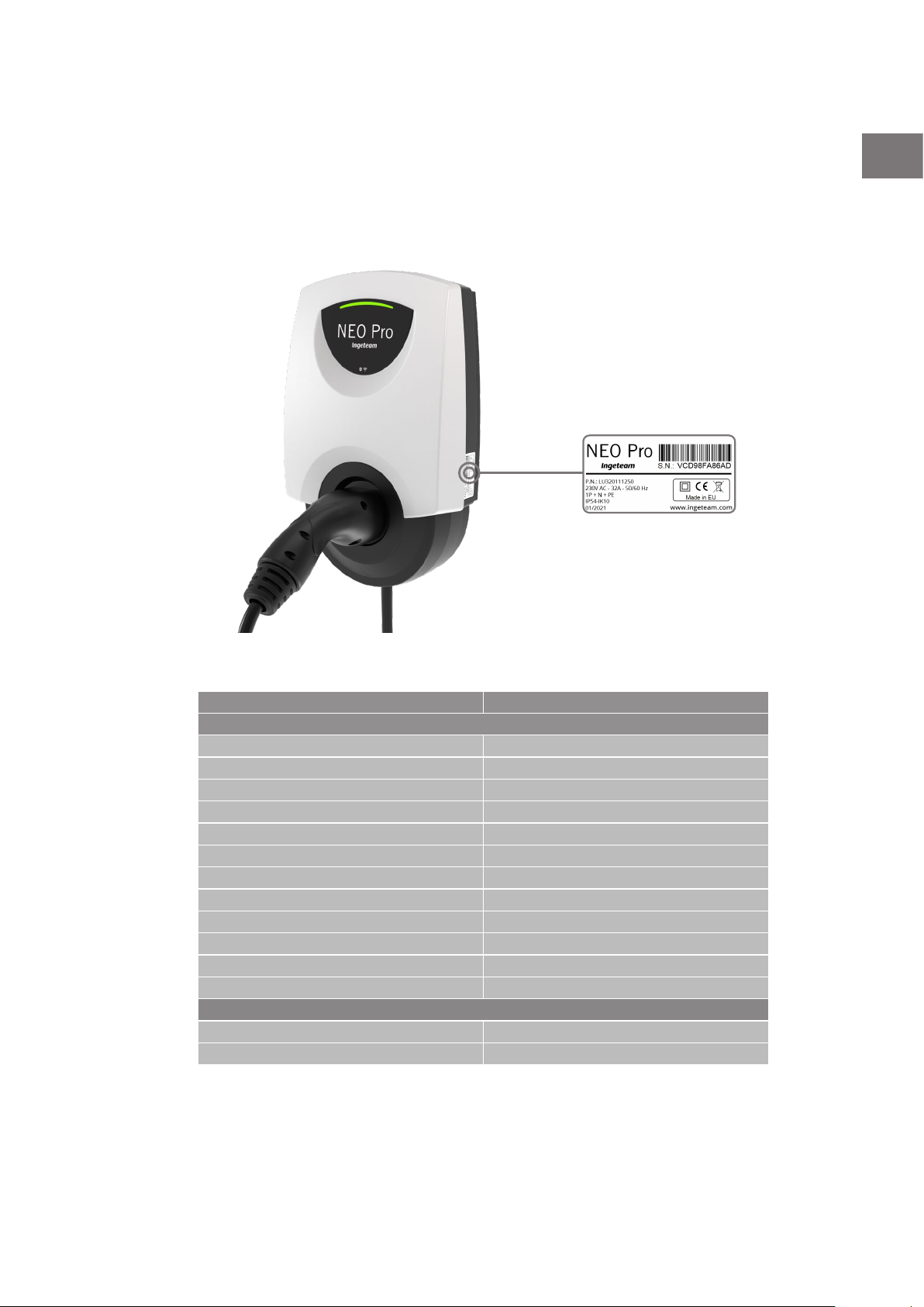
2.1. Identification of the charger............................................................................................................ 7
2.2. Elements included in the packaging ................................................................................................ 7
2.3. Optional accessories ...................................................................................................................... 8
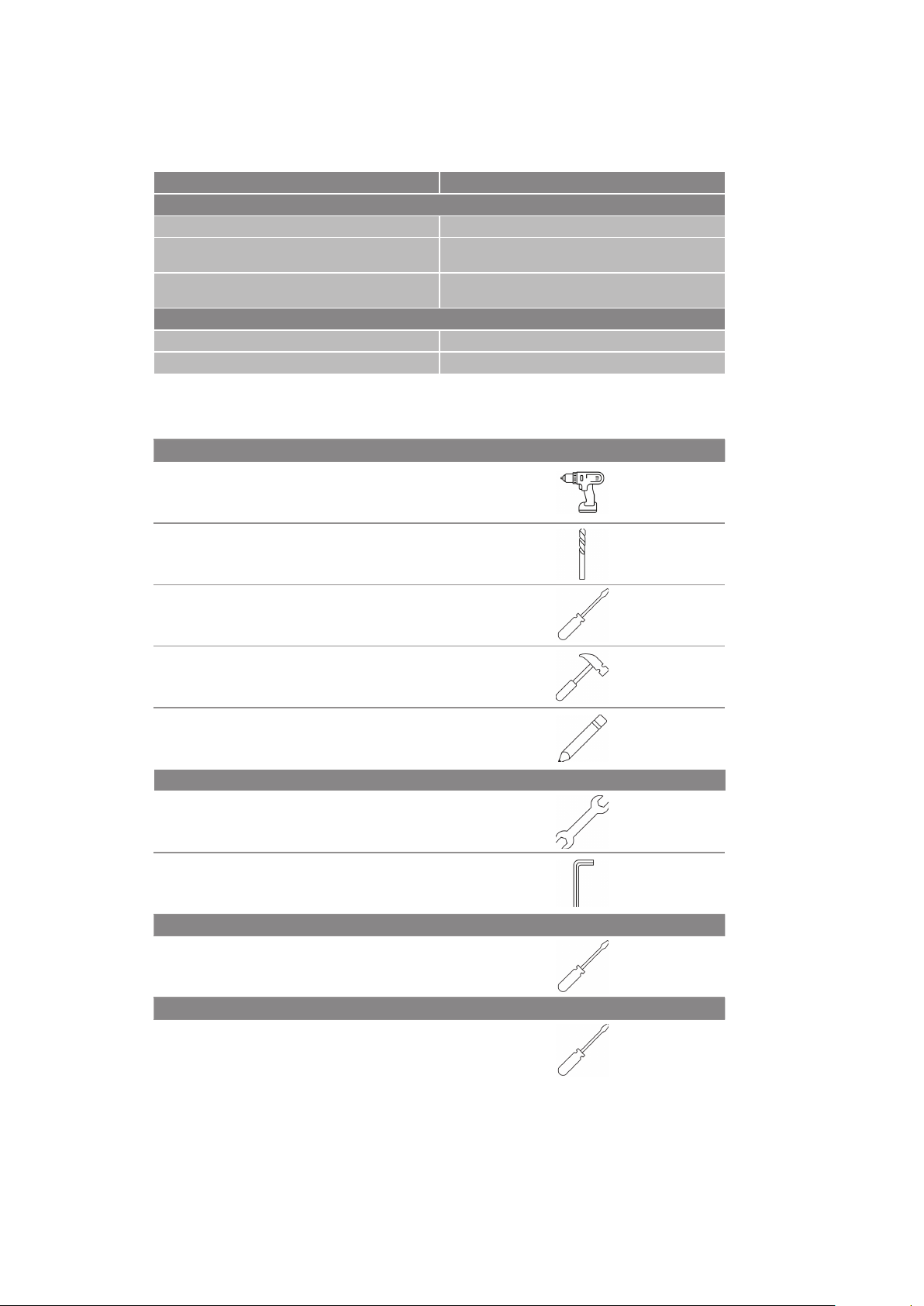
2.4. Required tools ............................................................................................................................... 8
3. Installation............................................................................................................................................ 9
3.1. Installation of the NEO or NEO Pro charger ...................................................................................... 9
3.1.1. Check the power supply cut .................................................................................................... 9
3.1.2. Check the connections ........................................................................................................... 9
3.1.3. Optional: install the stand element.......................................................................................... 9
3.1.4. Optional: Install the SIM card. ................................................................................................ 9
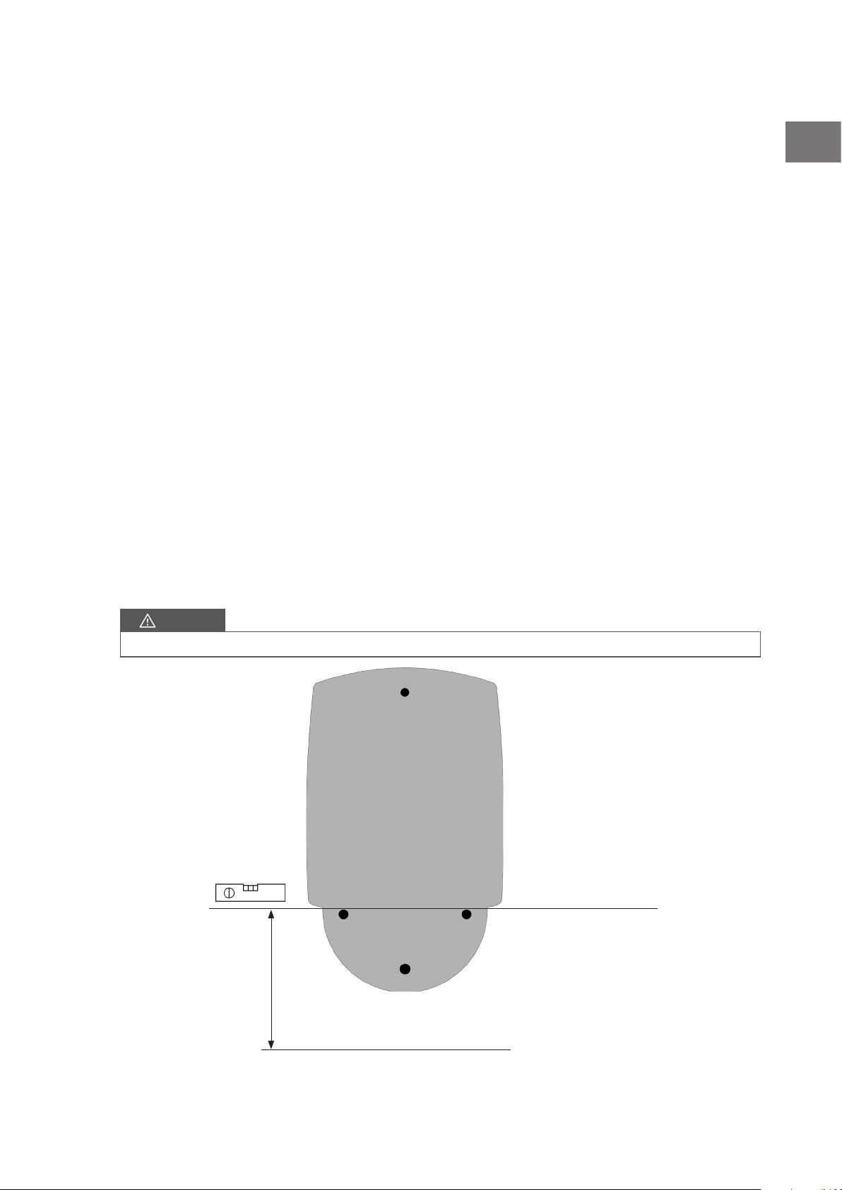
3.1.5. Place the template................................................................................................................. 9
3.1.6. Prepare the connections....................................................................................................... 10
3.1.7. Prepare the installation of the charger ................................................................................... 11
3.1.8. Fit the upper screw.............................................................................................................. 11
3.1.9. Connect the charger to the power .......................................................................................... 12
3.1.10. Optional: CURVE device installation (NEO single phase)........................................................ 12
3.1.11. Optional: CURVEx3 device installation (NEO three phase) ..................................................... 12
3.1.12. Optional: Connection of the charger to another charger or a communications element .............. 12
3.1.13. Hang the charger from the bushing...................................................................................... 13
3.1.14. Fix the charger to the wall .................................................................................................. 13
3.1.15. Install charging cable bracket ............................................................................................. 14
3.1.16. Supply power to the charger ............................................................................................... 14
3.2. SIM card installation.................................................................................................................... 14
3.3. Installation of the CURVE device................................................................................................... 15
3.4. Installation of the CURVEx3.......................................................................................................... 17
3.5. Connection of the charger to another charger or a communications element ...................................... 19
3.6. Installation of the STAND element (optional) .................................................................................. 21
4. Technical specifications........................................................................................................................ 24
4.1. Chargers ..................................................................................................................................... 24
4.2. Dimensions ................................................................................................................................. 25
4.3. Accessories ................................................................................................................................. 25
4.3.1. STAND ............................................................................................................................... 25
4.3.2. CURVE ............................................................................................................................... 26
4.3.3. CURVEx3............................................................................................................................ 27

ABV2013IQM01_ - Installation manual
1. Welcome
1.1. About this manual
This manual contains important and essential information for the correct installation of NEO series chargers and
their accessories.
This manual, including the images that appear in it, are the intellectual property of INGETEAM, who reserves the
right to modify its content without having to update the previous manuals. It will not be accessible to third parties
without their express authorization. It is only available for users.
It is not permitted to copy, disseminate or disclose this document, in whole or in part, nor make it available to
others, especially competing companies, without prior authorization from INGETEAM.
The images that appear in this manual are purely informative and have no contractual validity.
The original manual is written in Spanish. The translation of the original manual into different languages is for the
purpose of clarifying its content. If there are any discrepancies between the translated document and the original,
the original version takes precedence over the translation.
1.2. Warranty
INGETEAM guarantees this product and its accessories against any defects in materials and in the manufacturing
process for a period of 2 years from the date of purchase. During this period, INGETEAM will repair or replace any
defective product. In the event of repair or replacement, the warranty period for new items will be the remainder of
the original components, or 6 months, whichever is longer. The warranty will be voided in the following cases:
• Defects caused by an accident, improper use, inadequate maintenance or normal wear.
• Replacement, modification or incorporation of any part in an unauthorized way.
• Installation, repair or disassembly of the unit by unqualified personnel.
1.3. Safety measures
The charger must only be installed by qualified personnel following applicable local regulations.
• Use the unit within the parameters and conditions specified in “Technical specifications”.
• Visually inspect the unit before it is installed. Contact the distributor if faults, breakages, dirt or humidity
are detected.
• Take the necessary precautions in the event of having an electronic medical implant. Consult a doctor
about the effects of the charging process on the implant.
• Do not remove, eliminate or damage the unit's labels or stickers.
• Do not step on, hit or drop the charging cable or the connector.
• Do not tension the charging cable under any circumstances.
• Do not use extension cables or adapters for the charging cable.
• The charger must always be connected to the installation's ground connection.
• Do not install the charger near flammable, explosive or combustible materials, chemicals or solvents, gas
pipes, steam vents, radiators or batteries.
• Do not install the charger in areas susceptible to flooding, high humidity or running water.
• Before installing the charger, ensure that the assembly surface can withstand the mechanical stresses
associated with the weight of the charger and its use.
• This unit will be permanently connected to the AC supply network.
• The power supply line must be connected to an existing installation. This line must have the necessary
protections according to local regulations, and must always be of a maximum caliber equal to the
maximum output of the charger (32 A). This unit requires an external residual current protection.
6
Welcome
Ingeteam

ABV2013IQM01_ - Installation manual
EN
ES
FR
IT
2. Before starting
2.1. Identification of the charger
The charger model is visible on its panel (NEO or NEO Pro). The charger also has a label on the side that shows
which model it is.
2.2. Elements included in the packaging
Element Quantity
NEO or NEO Pro
NEO or NEO Pro Charger 1
Bushing 1
4.8x38 screw 1
4.8x90 screw 3
SX8x40 wall plug 4
Cap 3
Blanking plug 1
Blind grommet 1
Hollow crimp ferrule for 6 mm2cables 3 (single-phase NEO) - 5 (three-phase NEO)
Replacement ACCESS CODE label 1
Template for installation 1
Charging cable bracket 1
CURVE (NEO single phase)
CURVE 1
Flange 1
7
Before starting Ingeteam

ABV2013IQM01_ - Installation manual
2.3. Optional accessories
Element Quantity
STAND
STAND 1
M5x12 screw 1 (single STAND)
2 (double STAND)
M5x70 screw 3 (single STAND)
6 (double STAND)
CURVEx3
CURVEx3 Iskra IE38Mx 1
Smart Gateway Iskra SG-E1 1
2.4. Required tools
NEO and NEO Pro
Drill
8 mm drill bit
Phillips PH2 screwdriver
Hammer
Pencil or marker
STAND
Wrench
4 mm Allen or hex key
CURVE
3.2 mm flathead screwdriver
CURVEX3
Phillips PH2 screwdriver
8
Before starting
Ingeteam

ABV2013IQM01_ - Installation manual
EN
ES
FR
IT
3. Installation
3.1. Installation of the NEO or NEO Pro charger
3.1.1. Check the power supply cut
Make sure the power supply is interrupted at the point of installation of the charger.
3.1.2. Check the connections
Check that the required electrical wiring for powering the charger is available at the point of installation.
OPTIONAL: If a CURVE device will also be installed, check that the wiring from that device is also available. For
more information, see “Installation of the CURVE device”.
OPTIONAL: If the charger will be connected to a three-phase energy meter, communications equipment (modem,
router, switch, etc.) or another charger, check that the Ethernet wiring from that device is also available. For
more information, see “Installation of the CURVEx3” and/or “Connection of the charger to another charger or a
communications element”.
3.1.3. Optional: install the stand element
If it is necessary to install the STAND element to anchor the charger to the ground, see “Installation of the STAND
element (optional)”.
3.1.4. Optional: Install the SIM card.
If it is necessary to install the SIM card, see “3.2. SIM card installation”.
3.1.5. Place the template
Place the template in the desired position, approximately 1.2 m from the horizontal reference to the ground.
CAUTION
It is recommended to use a level to ensure that the template is perfectly level.
1.2 m
Ground
Connector height
9
Installation Ingeteam

ABV2013IQM01_ - Installation manual
3.1.6. Prepare the connections
Following the template’s indications, carry out the following steps:
1. Place the tube for the power supply wiring at the indicated height.
2. Cut and strip the cables to the recommended length.
3. Fit the ferrules.
CAUTION
Always use a suitable tool (crimper) to avoid bad connections that can cause overheating in the connection
terminals.
20 mm hollow
crimp ferrule
5.5 cm
Connection tube
25 cm
NEO / NEO Pro (single phase)
20 mm hollow
crimp ferrule
5.5 cm
Connection tube
25 cm
NEO Pro (three-phase)
10
Installation
Ingeteam

ABV2013IQM01_ - Installation manual
EN
ES
FR
IT
3.1.7. Prepare the installation of the charger
1. Mark the holes to be made.
2. Drill the holes.
3. Fit the wall plugs.
8 mm
1
2
3
3.1.8. Fit the upper screw
Fit the screw of the upper part and tighten it until it stops on the bushing.
CAUTION
In the case of the STAND, use the screws that come with it in the packaging.
Wall mounting: 4.8x38 screw
STAND assembly: M5x12 screw
11
Installation Ingeteam

ABV2013IQM01_ - Installation manual
3.1.9. Connect the charger to the power
Connect the electrical terminals of the power cable to the corresponding points on the charger.
CAUTION
Make sure that all screws are suitably tightened for effective contact of the active elements of the conductor.
Neutral
Phase 1
Phase 2
Phase 3
Ground
Neutral
Phase 1
Ground
NEO / NEO Pro (single phase) NEO Pro (three-phase)
• OPTIONAL: If a CURVE device is also going to be installed, connect the wiring from that device. For more
information, see “Installation of the CURVE device”.
• OPTIONAL: If the charger will be connected to a three-phase energy meter, to communications equipment
(modem, router, switch, etc.) or to another charger, connect the Ethernet wiring from that device. For
more information, see “Installation of the CURVEx3” and/or “Connection of the charger to another
charger or a communications element”.
3.1.10. Optional: CURVE device installation (NEO single phase)
If it is necessary to install the CURVE device, see “Installation of the CURVE device”.
3.1.11. Optional: CURVEx3 device installation (NEO three phase)
If it is necessary to install the three-phase energy meter, see “Installation of the CURVEx3”.
3.1.12. Optional: Connection of the charger to another charger or a
communications element
In the event that you need to connect the charger to another charger or a communications element, see
“Connection of the charger to another charger or a communications element”.
12
Installation
Ingeteam

ABV2013IQM01_ - Installation manual
EN
ES
FR
IT
3.1.13. Hang the charger from the bushing
Hang the charger on the upper screw bushing.
3.1.14. Fix the charger to the wall
1. Fit the three screws on the lower part of the charger and tighten them firmly.
2. Fit the caps to cover the three screws.
FRONTAL
Wall mounting: 4.8x90 screw
STAND assembly: M5x70 screw
1
2
13
Installation Ingeteam

ABV2013IQM01_ - Installation manual
3.1.15. Install charging cable bracket
1. Mark the holes to drill in the wall.
2. Drill the holes.
3. Fit the wall plugs.
8 mm
2
3
1
4. Place the screws.
3.1.16. Supply power to the charger
Close the cut-off element of the electrical circuit that powers the charger.
3.2. SIM card installation
1. Remove the 6 screws that join the front cover to the rear cover using a Torx head screwdriver, size T20.
Remove the frontal cover.
14
Installation
Ingeteam

ABV2013IQM01_ - Installation manual
EN
ES
FR
IT
2. Identify the SIM card housing on the electronic board.
3. Insert the SIM card in its housing following the steps below:
4. Close the housing again with the 6 screws.
3.3. Installation of the CURVE device
CAUTION
The CURVE device is designed to be used with the NEO or NEO Pro single-phase charger.
1. Select the circuit on which you wish to install the CURVE device.
At the meter output In the home circuit
METER
Contracted
power
Home power
Electric
vehicle
power
CURVE
PANEL PANEL
PANEL
METER
Contracted
power
Home power
Electric
vehicle
power
CURVE
PANEL
CAUTION
The operation of the CURVE device is independent of the direction of the active phase current that passes
through it.
15
Installation Ingeteam

ABV2013IQM01_ - Installation manual
2. Install the CURVE device in the active phase of the circuit you wish to measure (general or home).
Cables that connect to the charger
Active phase
3. Attach the CURVE device to the cable using the mounting flange.
Mounting flange
4. Run a 1.5 mm two-wire cable between the CURVE device and the charger.
5. Strip the cable 8 mm on each wire and connect it to the terminals of the CURVE device.
8 mm
16
Installation
Ingeteam

ABV2013IQM01_ - Installation manual
EN
ES
FR
IT
6. Strip the cable 8 mm on each wire and connect the CURVE device to the charger on the indicated pins.
NEO NEO Pro
3.4. Installation of the CURVEx3
CAUTION
The CURVEx3 device is made up of two elements: a three-phase energy meter and a Smart Gateway.
1. Select the circuit on which you wish to install the CURVEx3.
At the meter output In the home circuit
METER
Contracted
power
Home power
ENERGY
METER
Electric
vehicle
power
PANEL PANEL
PANEL
METER
Contracted
power
Home power
Electric
vehicle
power PANEL
ENERGY
METER
2. Install the CURVEx3 and the Smart Gateway next to each other, keeping the elements of each device that
allow infrared communication between them in contact.
CAUTION
The three-phase energy meter is designed to be installed on a DIN rail (DIN EN 60715).
17
Installation Ingeteam

ABV2013IQM01_ - Installation manual
3. Strip the power cables 10 mm and the neutral cable 8 mm.
4. Put the contacts of the power and neutral cables in the CURVEx3 and tighten the screws.
CAUTION
The incorrect or incomplete connection of voltage or other terminals can cause the device to malfunction or be
damaged.
L1, L2, L3: Phase lines.
N: Neutral
5. Prepare the wiring between the three-phase energy meter and the Smart Gateway (stripping the cables
6 mm at the ends that go to the latter), put the contacts of the power and neutral cables in the Smart
Gateway and tighten the screws.
Neutral
Phase 1
Phase 1
Phase 2
Phase 2
Phase 3
Phase 3
18
Installation
Ingeteam

ABV2013IQM01_ - Installation manual
EN
ES
FR
IT
6. Run an Ethernet cable with RJ45 connectors on both ends and connect it to the Smart Gateway and the
charger.
CAUTION
Connect it to either of the two RJ45 sockets on the charger.
NEO Pro (single-phase) NEO Pro (three-phase)
3.5. Connection of the charger to another charger or a
communications element
NEO Pro models have two local network sockets that, as well as allowing the connection of a three-phase energy
meter (see “Installation of the CURVEx3”), also allow the following connections:
• Connect the charger to communications equipment (modem, router, switch, etc.).
CAUTION
The equipment can be connected to either of the two sockets on the charger interchangeably.
19
Installation Ingeteam

ABV2013IQM01_ - Installation manual
• Connect several chargers to each other forming a group. All chargers in a group must be connected to the
same LAN network, either connected directly to each other, or using connection elements (e.g. switch).
Ethernet bridges
20
Installation
Ingeteam
Other manuals for NEO
2
This manual suits for next models
1
Table of contents
Languages:
Other Ingeteam Batteries Charger manuals

Ingeteam
Ingeteam INGEREV FUSION Street FS1MW User manual

Ingeteam
Ingeteam Ingerev Garage User manual

Ingeteam
Ingeteam Ingerev City User manual

Ingeteam
Ingeteam Ingerev Garage User manual

Ingeteam
Ingeteam INGEREV FUSION Installation manual

Ingeteam
Ingeteam INGEREV RAPID ST Series User manual

Ingeteam
Ingeteam INGEREV RAPID 50 Trio User manual

Ingeteam
Ingeteam Ingerev Garage User manual

Ingeteam
Ingeteam NEO User manual