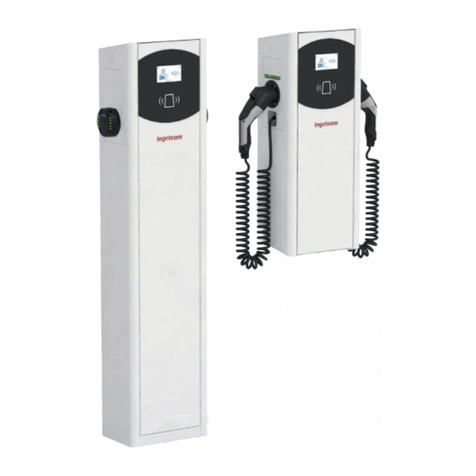
Ingeteam INGEREV RAPID 50 Trio User manual

INGEREV RAPID 50
Trio - Duo - One - One+
Installation and Operation Manual
Manual de instalación y uso
Manuel d’installation et usage
Manuale d’installazione e uso
Manual de instalaçao e uso

ABT2013IQM01_
01/2022
Ingeteam Power Technology, S.A. - Energy
Avda. Ciudad de la Innovación, 13
31621 SARRIGUREN (Navarra) - Spain
Tel.: +34 948 28 80 00
Fax.: +34 948 28 80 01
e-mail: electricmobility[email protected]
Service Call Center: +34 948 698 715

ABT2013IQM01_
English EN
Español ES
Français FR
Italiano IT
Português PT
3
Ingeteam

ABT2013IQM01_
The copy, distribution or use of this document or of its content requires written authorisation. Any breach thereof will be reported for
damages. All rights reserved including those of patent rights or design registration.
The conformity of the document content with the hardware described has been checked. However, discrepancies may exist. Liability
will not be assumed for total concordance. The information contained in this document is regularly reviewed and it is possible that
there may be changes in subsequent editions. Other functions may be available which are not covered by this document.
This document may be changed.
La copia, circulación o uso de este documento o de su contenido requiere un permiso por escrito. Su incumplimiento será
denunciado por daños y perjuicios. Todos los derechos están reservados, incluyendo aquellos que resulten de derechos de patentes
o registro del diseño.
La correspondencia del contenido del documento con el hardware ha sido comprobada. Sin embargo, pueden existir discrepancias.
No se asume ninguna responsabilidad por la concordancia total. La información que contiene este documento es revisada
regularmente y es posible que se produzcan cambios en siguientes ediciones.
El presente documento es susceptible de ser modificado.
La copie, distribution ou utilisation de ce document ou de son contenu requiert une autorisation écrite. Toute personne ne respectant
pas cette condition sera passible de poursuites. Tous les droits sont réservés, y compris ceux qui découlent des droits de brevets ou
d’enregistrement des conceptions.
La correspondance entre le contenu du document et le matériel a été vérifiée. Il peut toutefois exister des divergences. Aucune
responsabilité de concordance totale n’est assumée. Les informations contenues dans ce document sont régulièrement révisées et il
est possible que des changements surviennent dans les éditions à venir.
Le présent document est susceptible d’être modifié.
Per copiare, condividere o utilizzare il presente documento o il suo contenuto è necessaria un’autorizzazione scritta. Il mancato
rispetto di quest’obbligo sarà perseguito. Tutti i diritti sono riservati, compresi quelli risultanti da diritti di brevetti o dalla registrazione
del progetto.
La corrispondenza del contenuto del presente documento con l’hardware è stata verificata, tuttavia, possono sussistere discrepanze.
Si declina ogni responsabilità relativamente alla concordanza totale. Le informazioni contenute in questo documento sono
regolarmente sottoposte a revisione ed è possibile che siano inserite delle modifiche nelle prossime edizioni.
Questo documento può essere soggetto a modifiche.
A cópia, circulação ou utilização deste documento ou do respectivo conteúdo requer uma autorização por escrito. O seu
incumprimento será denunciado por danos e prejuízos. Todos os direitos estão reservados, incluindo aqueles que resultem de direitos
de patentes ou do registo do design.
A conformidade do conteúdo do documento com o hardware foi verificada. No entanto, podem existir discrepâncias. Não se assume
qualquer responsabilidade pela concordância total. As informações contidas neste documento são revistas regularmente e é possível
que se verifiquem alterações nas próximas edições.
O presente documento é susceptível de ser alterado.
4
Ingeteam

ABT2013IQM01_ - Installation and Operation Manual
EN
ES
FR
IT
PT
Important safety instructions
This section describes the safety warnings and the personal protective equipment and symbols used in the unit.
Safety conditions
General warnings
DANGER
Opening the enclosure does not imply there is no voltage inside.
The risk of electric shock exists even after disconnecting from the grid.
Only qualified personnel may open it, following the instructions in this manual.
It is strictly forbidden to gain access to the inside of the electrical panel through any other point than the
access cover provided for this purpose. Always gain access when the unit is voltage-free.
CAUTION
The operations described in the manual may be performed only by qualified personnel.
The status of qualified personnel referred to in this manual will be, as a minimum, that which meets all the
standards, regulations and laws regarding safety applicable to the tasks of installing and operating this unit.
The responsibility for designating qualified personnel will always fall to the company to which the personnel
belong. It is necessary to decide which workers are suitable or not for carrying out specific work to preserve their
safety at the same time as complying with occupational safety legislation.
These companies are responsible for providing appropriate training in electrical equipment to their personnel
and for familiarizing them with the contents of this manual.
All applicable safety-related legislation for electrical work must be complied with. Danger of electric shock.
Compliance with the safety instructions set out in this manual or in the suggested legislation does not imply
exemption from other specific standards for the installation, place, country or other circumstances that affect
the unit.
You must consider the set of conditions listed throughout this document as minimum requirements. It is always
preferable to shut off the main power supply. There may be faults in the installation that cause the unwanted
return of voltage. Danger of electric shock.
According to basic safety standards, the complete unit must be suitable to protect exposed workers against the
risk of direct and indirect contact. In any case the electrical parts of the work equipment must comply with the
provisions of the corresponding specific regulations.
According to basic safety standards, the electrical installation shall not entail a fire or explosion risk. Workers
must be duly protected against the risk of accidents caused by direct or indirect contact. The electrical
installation and protection devices must take into account the voltage, the external conditions and the
competence of persons who have access to parts of the installation.
To check the absence of voltage, it is compulsory to use measurement devices with category III-1100 V.
INFO
These instructions must be easily accessible close to the unit and located within reach of all users.
Before installation and start-up, please read these safety instructions and warnings carefully as well as all the
warning notices located on the unit. Ensure that all the warnings signs are perfectly legible and that those which
are damaged or have disappeared are restored.
Protection against direct contact is by means of the enclosure.
The unit has been tested according to the applicable regulations to comply with the safety requirements, the
values for insulation clearances and leakage paths for the voltages used.
5
Important safety instructions Ingeteam

ABT2013IQM01_- Installation and Operation Manual
Potential hazards for people
DANGER
Electric shock.
The equipment may remain charged after disconnecting the grid power.
Carefully follow the mandatory steps in the manual for removing the voltage.
Explosion.
There is a very low risk of explosion in very specific cases of malfunction.
The casing will protect people and property from the explosion only if it is correctly closed.
Crushing and joint injuries.
Always follow the indications in the manual on moving and placing the unit.
The weight of this unit can cause serious injury and even death if not handled correctly.
High temperature.
The flow of outlet air can reach high temperatures which can cause injury to anybody exposed to it.
Potential hazards for the equipment
DANGER
Cooling.
The unit requires particle-free air flow while it is operating.
Keeping the unit in the upright position and the inlets free of obstacles is essential for this air flow to reach the
inside.
Do not touch boards or electronic components. The more sensitive components can be damaged or destroyed by
static electricity.
Do not disconnect or connect any terminal while the unit is operating. Disconnect and check for absence of
voltage first.
With the aim of avoiding premature wear of the screwed joints on the unit's housing panels, removal and
installation of the screws must be done manually.
6
Important safety instructions
Ingeteam

ABT2013IQM01_ - Installation and Operation Manual
EN
ES
FR
IT
PT
Personal Protective Equipment (PPE)
When working on the unit, use the following safety equipment recommended by Ingeteam as a minimum.
Name Description
Safety footwear In compliance with standard UNE-EN-ISO 20345:2012 ANSI Z41.1-1991
Helmet with face shield In compliance with standard UNE-EN 397:1995, ANSI Z89.1-2014,provided
there are elements with voltage directly accessible.
Working clothes Close-fitting, non-flammable, 100% cotton
Dielectric gloves In compliance with standard EN 60903:2005 ASTM D 120-87
Tools and / or equipment used in live work must have at least Category III-1100 Volts insulation.
Should the country’s regulations demand another kind of personal protection, you should appropriately supplement
the equipment recommended by Ingeteam.
7
Important safety instructions Ingeteam

ABT2013IQM01_- Installation and Operation Manual
8
Contents
Ingeteam
Contents
Important safety instructions ....................................................................................................................... 5
Safety conditions................................................................................................................................... 5
Personal Protective Equipment (PPE) ...................................................................................................... 7
Contents ................................................................................................................................................... 8
1. About this manual................................................................................................................................ 10
1.1. Scope and nomenclature .............................................................................................................. 10
1.2. Recipients................................................................................................................................... 10
1.3. Symbols...................................................................................................................................... 10
2. Unit description................................................................................................................................... 11
2.1. Overview ..................................................................................................................................... 11
2.2. Models........................................................................................................................................ 11
2.3. Connectors.................................................................................................................................. 11
2.3.1. Connectors for DC charging .................................................................................................. 11
2.3.2. Connectors for AC charging................................................................................................... 12
2.4. Protection ................................................................................................................................... 13
2.5. Wattmeters.................................................................................................................................. 14
2.6. Accessories equipped as standard ................................................................................................. 14
2.7. Optional accessories .................................................................................................................... 14
2.8. Electrical safety........................................................................................................................... 14
2.8.1. Overvoltage category (OVC) ................................................................................................... 14
2.9. Acoustic contamination ................................................................................................................ 14
2.10. Electrical diagram of the system.................................................................................................. 15
2.11. Specification table ..................................................................................................................... 17
2.12. Description of cable inlets .......................................................................................................... 18
3. Receipt of the unit and storage.............................................................................................................. 19
3.1. Reception ................................................................................................................................... 19
3.2. Unit identification........................................................................................................................ 19
3.3. Transport damage ........................................................................................................................ 19
3.4. Storage....................................................................................................................................... 19
3.5. Conservation................................................................................................................................ 19
4. Equipment transport ............................................................................................................................ 20
4.1. Center of gravity .......................................................................................................................... 20
4.2. Unpacking .................................................................................................................................. 20
4.3. Transport..................................................................................................................................... 21
5. Preparation for installing the unit .......................................................................................................... 22
5.1. Environment................................................................................................................................ 22
5.2. Environment................................................................................................................................ 23
5.3. Environmental conditions ............................................................................................................. 23
5.4. Supporting Surface and Fastening ................................................................................................. 24
5.5. Fuse requirements ....................................................................................................................... 25
5.6. Type of grid ................................................................................................................................. 26
5.7. Cabling length ............................................................................................................................. 27
5.8. External disconnection device ....................................................................................................... 27
5.9. Medium voltage transformer.......................................................................................................... 27
6. Installing the unit ................................................................................................................................ 28
6.1. General requirements for installation ............................................................................................. 28
6.2. Fastening the unit........................................................................................................................ 28
7. Connection of accessories..................................................................................................................... 30
7.1. Safety instructions for connecting accessories ................................................................................ 30
7.2. Ethernet communication .............................................................................................................. 30
7.2.1. Cabling requirements ........................................................................................................... 30
7.2.2. Connection process.............................................................................................................. 30
8. AC connection ..................................................................................................................................... 31
8.1. Safety instructions for the AC connection....................................................................................... 31
8.2. Wiring requirements for the AC connection..................................................................................... 31
ABT2013IQM01_ - Installation and Operation Manual
EN
ES
FR
IT
PT
9
Contents Ingeteam
8.3. Cabling entrances for the AC connection ........................................................................................ 32
8.4. AC connection process ................................................................................................................. 33
9. First connection to the electric grid........................................................................................................ 34
9.1. Unit inspection............................................................................................................................ 34
9.1.1. Inspection........................................................................................................................... 34
9.1.2. Hermetic sealing of the unit ................................................................................................. 35
10. Software update................................................................................................................................. 36
10.1. Update via USB......................................................................................................................... 36
10.2. Automatic software update ......................................................................................................... 36
10.3. Software update via the INGEREV WEB Manager .......................................................................... 37
11. Configuration..................................................................................................................................... 38
11.1. Local connection ....................................................................................................................... 38
11.1.1. Local connection via Ethernet ............................................................................................. 38
11.1.2. Local connection via Wi-Fi.................................................................................................. 39
11.2. Remote connection .................................................................................................................... 39
12. Using the unit ................................................................................................................................... 40
12.1. Charging screen......................................................................................................................... 40
12.2. Charging process ....................................................................................................................... 41
13. Troubleshooting ................................................................................................................................. 42
13.1. Alarms...................................................................................................................................... 42
14. Shutting down the unit ....................................................................................................................... 43
15. Maintenance ..................................................................................................................................... 44
15.1. Safety conditions ....................................................................................................................... 44
15.2. Condition of hoses and charging connectors ................................................................................. 44
15.3. Condition of the housing............................................................................................................. 44
15.4. Condition of cables and terminals................................................................................................ 44
15.5. Changing the fuse...................................................................................................................... 45
15.6. Cleaning or replacing filters ........................................................................................................ 46
15.7. Changing the fans...................................................................................................................... 47
15.8. Changing the power blocks ......................................................................................................... 49
16. Waste handling .................................................................................................................................. 51

ABT2013IQM01_- Installation and Operation Manual
1. About this manual
The purpose of this manual is to describe the INGEREV RAPID 50 units and to provide appropriate information for
their correct reception, installation, start-up, maintenance and operation.
1.1. Scope and nomenclature
This manual is applicable to the following units:
Complete name Abbreviation
INGEREV RAPID 50 Trio Trio
INGEREV RAPID 50 Duo Duo
INGEREV RAPID 50 One One
INGEREV RAPID 50 One+ One+
1.2. Recipients
This document is intended for qualified personnel.
The status of qualified personnel referred to in this manual will be, as a minimum, that which meets all the
standards, regulations and laws regarding safety applicable to the tasks of installing and operating this unit.
The responsibility for designating qualified personnel will always fall to the company to which the personnel
belong. It is necessary to decide which workers are suitable or not for carrying out specific work to preserve their
safety at the same time as complying with occupational safety legislation.
These companies are responsible for providing appropriate training in electrical equipment to their personnel and
for familiarizing them with the contents of this manual.
1.3. Symbols
Throughout this manual we include warnings to highlight certain information. Relative to the nature of the text,
there are three types of warnings:
DANGER This indicates a hazard to personnel or the charger.
CAUTION Indicates importance.
INFO Additional information or references to other parts of the document or documents.
10
About this manual
Ingeteam

ABT2013IQM01_ - Installation and Operation Manual
EN
ES
FR
IT
PT
2. Unit description
2.1. Overview
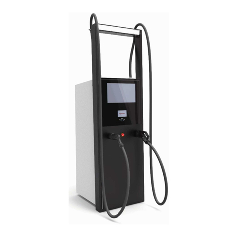
INGEREV RAPID 50 chargers are a multi-standard fast charging model designed for the fast charging requirements
of the latest electric vehicles, allowing to recover up to 100km of range in no more than 20minutes.
The different models of the INGEREV RAPID 50 are compatible with mode 4 with standards CHAdeMO and CCS in
DC and with mode 3 with AC Type 2 in AC.
They have been designed for use outdoors and may be installed in locations with unrestricted access. Given its
nature, this is a fixed, freestanding unit classified as Class I equipment.
2.2. Models
The INGEREV RAPID 50 chargers have several models with the following connector types available:
Connector type
DC AC
CCS CHAdeMO AC Type 2
INGEREV RAPID 50 Trio
INGEREV RAPID 50 Duo
INGEREV RAPID 50 One
INGEREV RAPID 50 One+
Equipped // Not equipped
These models are designed to remain connected to the public AC grid. They all generate DC current and the
INGEREV RAPID 50 Trio also generates AC current.
2.3. Connectors
2.3.1. Connectors for DC charging
The following connectors are based on DC fast charging standards for electric vehicles.
CCS
PE
DC+ DC-
CP PP
PP: Proximity Pilot
CP: Control Pilot
PE: Protective Earth
DC+
DC-
11
Unit description Ingeteam

ABT2013IQM01_- Installation and Operation Manual
CHAdeMO
1
1
4
4
3
6
6+
-
5
5
12 V
12 V
2
2
7
7
10
10
9
9
8
8
Power lines
Charger side Vehicle side
Control lines
CAN BUS
2.3.2. Connectors for AC charging
The following connector is based on AC fast charging standards for electric vehicles.
IEC 62196-2 AC Type 2
PE
CP
N
PP
L1
L2L3
PP: Proximity Pilot
CP: Control Pilot
PE: Protective Earth
N: Neutral
L1: Phase 1
L2: Phase 2
L3: Phase 3
12
Unit description
Ingeteam

ABT2013IQM01_ - Installation and Operation Manual
EN
ES
FR
IT
PT
2.4. Protection
This charging station has several protections, as described below.
A
B
D
C
E F
RD3 RD1
Q4 QAC Q2
Only Trio and
One+
Charging
inAC
Charging
inDC AUX
A. Q4 (AC). 63A CurveC thermal magnetic
circuit breaker (only Trio and One+)
B. RD3 (AC). 30mA/300mA* 63A Type B
residual current circuit breaker (only Trio and
One+)
C. QAC (DC). 100A CurveC thermal magnetic
circuit breaker
D. RD1 (DC). 30mA 100A Type A residual
current circuit breaker
E. Q2 (auxiliaries). 6A CurveC thermal magnetic
circuit breaker
F. RD2 (auxiliaries). 30mA 25A Type AC
residual current circuit breaker
*30mA or 300mA according to the regulations of the destination country.
13
Unit description Ingeteam

ABT2013IQM01_- Installation and Operation Manual
2.5. Wattmeters
The charging station has MID wattmeters, as described below.
B
A
A. P1 (DC). MID wattmeter for calculating the
energy in DC charging
B. P2 (AC). MID wattmeter for calculating the
energy in AC charging (only Trio and One+)
2.6. Accessories equipped as standard
• Ethernet communication.
• Local communication with other INGEREV stations.
• Compatible with OCPP.
• Authentication via RFID / NFC cards.
• Interface via display.
• Steel enclosure highly resistant against adverse weather conditions.
2.7. Optional accessories
These units may include the following optional accessories:
• 3G Communication.
• Wi-Fi communication.
2.8. Electrical safety
The design values for electrical safety can be found below.
2.8.1. Overvoltage category (OVC)
These units have been designed with OVC III in AC.
2.9. Acoustic contamination
The unit produces a buzz when in operation. The noise level is less than or equal to 59 dB. Do not place it in
an occupied room, or on light supports which might amplify this buzz. The mounting surface must be firm and
appropriate for the weight of the unit.
14
Unit description
Ingeteam

ABT2013IQM01_ - Installation and Operation Manual
EN
ES
FR
IT
PT
2.10. Electrical diagram of the system
INGEREV RAPID 50 Trio
AC DC
DC DC
A B C D
E
F
A G H I
INGEREV RAPID 50 Duo
AC DC
DC DC
A B C D
E
F
INGEREV RAPID 50 One
AC DC
DC DC
A B C D E
15
Unit description Ingeteam

ABT2013IQM01_- Installation and Operation Manual
INGEREV RAPID 50 One+
AC DC
DC DC
A B C D E
A G H I
A. Supply
B. Thermal magnetic circuit breaker and residual
current device
C. EMI filter
D. Wattmeter
E. CCS connector
F. CHAdeMO connector
G. Thermal magnetic circuit breaker and residual
current device
H. Wattmeter
I. Type 2 AC connector
16
Unit description
Ingeteam

ABT2013IQM01_ - Installation and Operation Manual
EN
ES
FR
IT
PT
2.11. Specification table
INGEREV RAPID 50 Trio / Duo / One / One+
AC input (for DC output)
Voltage Three phases + neutral + earth; 400Vac±15%
Frequency 50Hz
Rated current 77A
Rated power 53kVA
Efficiency >94%
Power factor >0.98
AC input (for AC output)(1)
Voltage Three phases + neutral + earth; 400Vac±15%
Frequency 50Hz
Rated current 63A
Rated power 43,5kVA
Charging connectors AC Mode 3 Type 2
Output (DC)
Voltage range 50~500V
Maximum current 125A
Maximum power 50kW
Charging connectors CCS Type 2 / CHAdeMO (2)
Regulations and safety compliance
Standards IEC61851-1, IEC61851-23, IEC61851-24, CHAdeMO1.0.0, DIN70121,
ISO15118, IEC61000
Overcurrent protection 63A Curve C thermal magnetic circuit breaker for charging in AC
100A Curve C thermal magnetic circuit breaker for charging in DC
Protection against indirect contacts
63A 30mA / 300mA Type B residual current circuit breaker for charging in
AC (2)(3)
100A 30mA Type A residual current circuit breaker for charging in DC
Overvoltage protection Type III surge arrester
General information
Cooling system Forced ventilation
Stand-by consumption <100W
Cabling length 3.8m
Operating temperature -25ºC~60ºC
Humidity 0~95% (without condensation)
Weight 620kg
Dimensions 785x700x1900mm
Protection class IP54 / IK10 (IK08 display and ventilation grilles)
Markings CE
Maximum altitude Up to 2000m
Noise level ≤ 59 dB
(1) only for Trio and One+
(2) only for Trio and Duo
(3) 30mA or 300mA according to the country's regulations.
17
Unit description Ingeteam

ABT2013IQM01_- Installation and Operation Manual
2.12. Description of cable inlets
64
22
32
64 56 35151
122,5
218,5
A
B
C
A. AC supply. Admissible hose range 6~20mm.
B. Earth connection for AC supply. Admissible
hose range 6~20mm.
C. Ethernet cabling and other uses. M20 cable
gland. Admissible hose range 6~13mm.
18
Unit description
Ingeteam

ABT2013IQM01_ - Installation and Operation Manual
EN
ES
FR
IT
PT
3. Receipt of the unit and storage
3.1. Reception
Keep the unit in its packaging until immediately before installation.
3.2. Unit identification
The serial number of the unit is its unique identifier. You must quote this number in any communication with
Ingeteam.
The unit’s serial number is marked on the specifications plate.
3.3. Transport damage
If the unit has been damaged during transport, proceed as follows:
1. Do not proceed with the installation.
2. Notify the distributor immediately within five days of receipt of the unit.
If ultimately the unit has to be returned to the manufacturer, the original packaging must be used.
3.4. Storage
CAUTION
Failure to follow the instructions in this section may lead to damage to the unit.
Ingeteam accepts no liability for damage resulting from the failure to follow these instructions.
If the unit is not installed immediately after reception, the following points should be taken into account in order to
avoid damage:
• The unit must be stored in its original packaging.
• Keep the unit free of dirt (dust, shavings, grease, etc.) and away from rodents.
• Keep it away from water splashes, welding sparks, etc.
• Cover the unit with a breathable protective material in order to prevent condensation due to ambient
humidity.
• Units in storage must not be subjected to weather conditions other than those indicated in section “2.11.
Specification table”.
• It is very important to protect the unit from chemical products which can cause corrosion, as well as from
salty atmospheres.
• Do not store the unit outdoors.
3.5. Conservation
In order to permit correct conservation of the units, they must not be removed from their original packaging until it
is time to install them.
In case of prolonged storage, use dry places, avoiding, as far as possible, sharp changes in temperature.
Deterioration of the packaging (tears, holes, etc.) prevents the units from being kept in optimum conditions before
installation. Ingeteam accepts no liability in the case of failing to observe this condition.
19
Receipt of the unit and storage Ingeteam

ABT2013IQM01_- Installation and Operation Manual
4. Equipment transport
You must protect the unit, during transport, from mechanical knocks, vibrations, water splashes (rain) and any
other product or situation which may damage it or alter its behavior.
Failure to observe these instructions may lead to loss of warranty on the product, for which Ingeteam is not
responsible.
4.1. Center of gravity
Bear in mind the center of gravity of the unit whenever it is moved. The approximate location of center of gravity is
specified below.
= =
740
285 416
4.2. Unpacking
Correct handling of the units is vitally important in order to:
• Prevent damage to the packaging which enables them to be kept in optimum condition from shipping
until they are installed.
• Avoid knocks and/or falls which may harm the mechanical features of the units, e.g. cause incorrect
closure of doors, loss of IP rating, etc.
• Avoid, as far as possible, vibrations which may cause subsequent malfunction.
If you observe any anomaly, please contact Ingeteam immediately.
Separating the packaging
You can deliver all the packaging to an authorized non-hazardous waste management company.
In any event, each part of the packaging may be recycled as follows:
• Plastic (polystyrene, bag and bubble wrap): the appropriate container.
• Cardboard: the appropriate container.
20
Equipment transport
Ingeteam
This manual suits for next models
2
Table of contents
Languages:
Other Ingeteam Batteries Charger manuals

Ingeteam
Ingeteam INGEREV RAPID ST Series User manual

Ingeteam
Ingeteam NEO User manual

Ingeteam
Ingeteam Ingerev Garage User manual

Ingeteam
Ingeteam INGEREV FUSION Street FS1MW User manual

Ingeteam
Ingeteam Ingerev Garage User manual

Ingeteam
Ingeteam Ingerev Garage User manual

Ingeteam
Ingeteam NEO User manual

Ingeteam
Ingeteam Ingerev City User manual

Ingeteam
Ingeteam INGEREV FUSION Installation manual