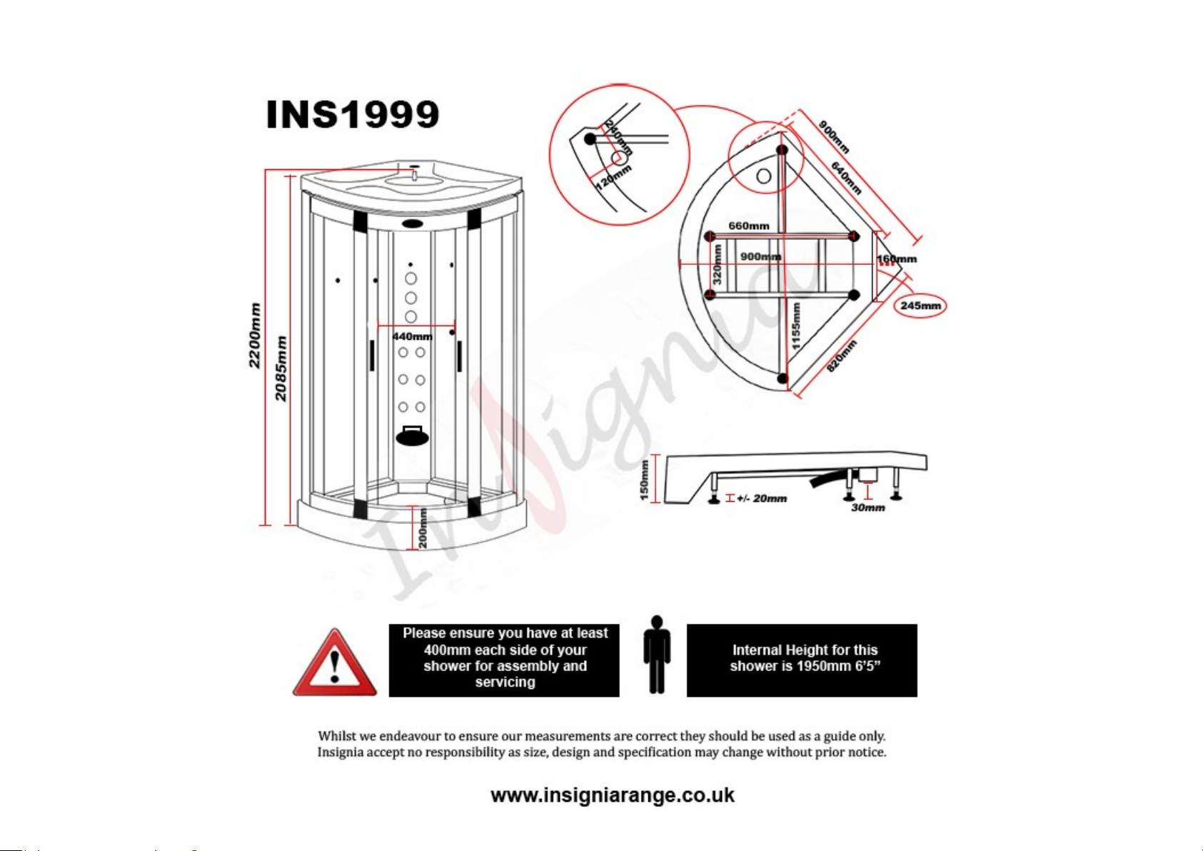
Insignia INS1999 User manual
Other Insignia Shower Cabin manuals

Insignia
Insignia ES Series User manual

Insignia
Insignia GT8721 User manual

Insignia
Insignia GT8727 User manual

Insignia
Insignia INS8059R User manual

Insignia
Insignia INS8058 User manual

Insignia
Insignia INS1057.1 User manual

Insignia
Insignia INS3000 User manual

Insignia
Insignia INS8058R User manual

Insignia
Insignia 1100R ES Series User manual

Insignia
Insignia GT003 User manual

Insignia
Insignia GT5000L User manual

Insignia
Insignia GT8004a User manual

Insignia
Insignia INS9001 User manual

Insignia
Insignia ES004 User manual

Insignia
Insignia INS8727 User manual

Insignia
Insignia 9008 User manual

Insignia
Insignia INS8721 User manual

Insignia
Insignia 9015 User manual

Insignia
Insignia GT0509 User manual

Insignia
Insignia INS8059.1R User manual


Popular Shower Cabin manuals by other brands


agape
agape FLAT D E1P Instructions for installation

glass 1989
glass 1989 nonsolodoccia home 140/90 manual

AM.PM
AM.PM ADMIRE STEAM CABIN A Assembly instructions

Schulte
Schulte MasterClass D1209030 Assembly instructions

Linie
Linie Tarifa installation guide

US HORIZON
US HORIZON SORRENTO Series Assembly instructions

Arblu
Arblu PERSEO ANGOLO Q-R 2SL+1LF Assembling instructions

Novellini
Novellini R90 base p.80 Instructions for installation, use and maintenance manual

SANPLAST
SANPLAST KP1DJa/TX5b Installation instruction

Kohler
Kohler Sterling 2375 Series installation guide

ELEGANT
ELEGANT SPR870 quick start guide

Jacuzzi
Jacuzzi frame in2 installation manual