Inspur NF5260FM6 User manual

Inspur Server NF5260FM6
User Manual
Document Version: V1.0
Release Date: 2021/05/28

Inspur Proprietary. Do Not Duplicate or Distribute.
Copyright © 2021 Inspur Electronic Information Industry Co., Ltd. All rights
reserved.
No part of this document may be reproduced or transmitted in any form or by
any means without prior written consent of Inspur.
Environmental Protection
Please dispose the packaging of our products at a waste collection station for
recycling to facilitate pollution prevention and environmental protection.
Trademarks
Inspur and Inspur Logo are the registered trademarks of Inspur.
All the other trademarks or registered trademarks mentioned herein are the
property of their respective holders.
Security Statement
Inspur is intensely focused on the product safety of servers and has placed a
high priority on this. For better understanding of this product, carefully read
through the following security risk statements.
When changing an application of a server or replacing one, you may restore
BIOS and BMC firmware settings to factory defaults, delete information, and
clear logs to protect data privacy. We also recommend that you use a trusted
third-party eraser tool to fully erase data on the drives.
The products, services or features you purchased may obtain or use some
personal data during operation or fault locating. There should be user
privacy policies in place with adequate measures implemented in
accordance with the applicable laws to ensure that users' personal data
are fully protected.
You can contact our Inspur customer service representative to obtain our
Statement on Open-source Software for Servers.
Some interfaces and commands for production, assembly and return-to-
depot, and advanced commands for locating faults, if used improperly,
may cause equipment abnormality or business interruption. This is not
described herein. Please contact Inspur for such information.
Inspur has established emergency response procedures and action plans
for security vulnerabilities, so that product safety issues can be dealt in a
timely manner. Please contact Inspur Customer Service for any safety
problems found or necessary support on security vulnerabilities when
using our products.

Inspur Proprietary. Do Not Duplicate or Distribute.
Inspur shall remain committed to safety of our products and solutions to
achieve better customer satisfaction.
Disclaimer
The products, services, or features you purchase shall be bound by the
contract entered into between you and Inspur Group. All or part of the
products, services and features described herein may not be within your
purchase or usage scope. Unless otherwise agreed in the contract, Inspur
makes no express or implied statement or warranty on the contents herein.
Images provided herein are for reference only and may contain information
or features that do not apply to your purchased model. This manual is only
used as a guide. Inspur shall not be liable for any damage, including but not
limited to loss of profits, loss of information, interruption of business,
personal injury, or any consequential damage incurred before, during, or
after the use of our products. Inspur assumes you have sufficient knowledge
of servers and are well trained in protecting yourself from personal injury or
product damages during operation and maintenance. The information in this
manual is subject to change without notice. Inspur shall not be liable for
technical or editorial errors or omissions contained in this manual.
Technical Support
Global Service Hotline: 1-844-860-0011 (toll-free)/1-760-769-1847 (DID)
Address: No. 1036, Langchao Road, Jinan, Shandong Province, China
Inspur Electronic Information Industry Co., Ltd.
Postal Code: 250101

Foreward
Abstract
This manual describes the server's specifications, features, hardware setup,
warranty information and troubleshooting, which will help users to
understand how best to utilize the server and all its functionalities.
Target Audience
This manual is intended for:
Technical support engineers
Product maintenance engineers
It is recommended that server installation, configuration, or maintenance is
performed by experienced technicians with knowledge in servers only.
Safety Precautions
If your purchases do not include Inspur on-site installation service, make
sure that you inspect the shipping cartons before unpacking the
equipment. If a shipping carton appears severely damaged, water
immersed, or the seal or pressure-sensitive adhesive tape (PSA) is broken,
report this based on your purchase channel. If you purchased from a
third-party supplier, contact your supplier directly; if you purchased
through Inspur direct sales stores, call Inspur service hotline 1-844-860-
0011/1-760-769-1847 for technical support.
For your safety, please do not disassemble the server's components,
extend configuration or connect other peripherals arbitrarily. You can
contact Inspur for our support and guidance.
Before disassembling the server's components, please be sure to
disconnect all the cables connected to the server.
Please install the product-compatible operating system and use the
driver that comes with the server or provided by Inspur. You can go to our
official site, on the Top Navigator, click on Support > Product Support >
Drivers, and then find the correct driver of your product based on the
prompt. An incompatible operating system or a non-Inspur driver may
cause compatibility issues and affect the normal use of the product.
Inspur will not assume any responsibility or liability for this.

BIOS and BMC settings are critical to configuring your server. Unless you
have specific requirements, always use the factory defaults. Do not make
unauthorized modifications. Change the BMC password the first time you
log in.
Symbol Conventions
The symbols that may be found in this document are defined as follows.
Symbol
Description
A potential for serious injury, or even death if not
properly handled
A potential for minor or moderate injury if not properly
handled
A potential loss of data or damage to equipment if not
properly handled
Operations or information that requires special attention
to ensure successful installation or configuration
Supplementary description of important information
Revision History
Version
Date
Description of Changes
V1.0
2021/05/28
Initial release

Table of Contents
Safety Instructions......................................................................................1
Warnings.........................................................................................................1
Precautions .....................................................................................................2
Product Specifications ................................................................................5
Introduction ....................................................................................................5
2.1.1 Features................................................................................................5
2.1.2 9 × 3.5” Configuration...........................................................................6
2.1.3 16 × 2.5” Configuration.........................................................................6
Features and Specifications ............................................................................6
Power Efficiency ..............................................................................................9
Component Description............................................................................ 12
Front Panel Components............................................................................... 12
3.1.1 9 × 3.5” Bays .......................................................................................12
3.1.2 16 × 2.5” Bays .....................................................................................13
3.1.3 Front Control Panel Button with LED ...................................................13
3.1.4 Drive Tray LEDs ................................................................................... 14
Rear Panel.....................................................................................................15
Mainboard Layout......................................................................................... 16
3.3.1 CMOS Clear Jumper .............................................................................18
Structure ....................................................................................................... 18
Operation................................................................................................. 20
Powering the Server On ................................................................................ 20
Powering the Server Off ................................................................................ 20
Extending the server from the rack ............................................................... 20
Removing the Server Top Cover ....................................................................21
Installing the Server Top Cover......................................................................22
Removing the PCIe Riser Assembly................................................................22
Installing the PCIe Riser Assembly.................................................................23
Removing the Air Director .............................................................................23

Hardware Components ............................................................................ 25
Introduction .................................................................................................. 25
Processor Components .................................................................................25
DIMM Components ........................................................................................28
5.3.1 How to Populate DIMMs......................................................................28
5.3.2 DIMM Installation Procedure...............................................................29
Hot-swap Drive Components ........................................................................30
Redundant Hot-Swap Power Supply Components ........................................31
Expansion Card Components ........................................................................ 33
Air Director Components ...............................................................................34
Fan Module Components .............................................................................. 35
Cabling..................................................................................................... 37
Firmware Upgrade and Configuration ...................................................... 38
Fault Diagnosis and Troubleshooting ....................................................... 39
FAQ About Hardware ....................................................................................39
8.1.1 No Power on Boot...............................................................................39
8.1.2 No Display after Powering-on ............................................................40
8.1.3 Status LED Alarm of the Front Panel ...................................................40
8.1.4 Stuck on Self-test or Other Screens Upon Boot.....................................41
8.1.5 Power Module LED Not Lit or Turning Red...........................................41
8.1.6 Abnormal Drive Status LEDs................................................................42
8.1.7 Excessive Noise from Chassis Fans .....................................................43
8.1.8 Server Alarm Ringing.......................................................................... 43
8.1.9 Keyboard and Mouse Not Work ..........................................................44
8.1.10 USB Port Problem ...............................................................................44
FAQ About System Software..........................................................................45
8.2.1 FAQ About OS Installation................................................................... 45
8.2.2 Error while Installing Operating System via PXE .................................46
8.2.3 Memory Capacity Error .......................................................................46
8.2.4 System Network Error .........................................................................47

Battery Replacement ................................................................................ 48
Electrostatic Discharge (ESD) .................................................................... 49
ESD Prevention.............................................................................................. 49
Anti-ESD Grounding Methods........................................................................49
Server Entrance and Runtime Environment Requirements ........................50
Ambient Temperature ................................................................................... 50
Reliability ......................................................................................................50
Altitude and Atmospheric Pressure ............................................................... 51
Alternating Temperature and Humidity.........................................................51
Extended Operating Temperature................................................................. 51
Limits of the Extended Operating Temperature.............................................51
Cooling Limits................................................................................................52
Runtime Environment Requirements.............................................................52
Electromagnetic Requirements ..................................................................... 56
Power Supply Requirements ......................................................................... 57
11.10.1 Requirements for AC Power Supply................................................57
11.10.2 Requirements for DC Power Supply................................................58
11.10.3 Considerations on AC Power Supply ..............................................58
11.10.4 HVDC Power Supply .......................................................................58
11.10.5 Requirements for HVDC Power Supply ...........................................58
11.10.6 Considerations on HVDC Power Supply..........................................59
11.10.7 DC Power Supply............................................................................60
Service Terms ........................................................................................... 61
Appendices .............................................................................................. 62
Reference Tables of Neodymium Content in HDDs........................................ 62
Glossary ........................................................................................................ 63
Abbreviations................................................................................................ 69

1
Safety Instructions
Warnings
The following warnings indicate potential hazards that may cause property damage,
personal injury, or death.
1. The power supply units of this system may generate a high voltage and
dangerous energy that can result in personal injury. Without the permission of
Inspur, do not remove the chassis cover to install, remove, or replace any
components in the system. Such work can only be performed by a qualified
technician who has been trained by Inspur.
2. Ensure the system is powered by an external power supply that matches the
ratings indicated on the nameplate. Please use a voltage regulator or UPS
(uninterruptible power supply) to prevent damage to the system that is caused
by voltage sags or surges.
3. If an extension cable is required, always use a three-core cable with a properly
grounded plug, and ensure that the total rated current of all the devices
connected to the extension cable does not exceed 80% of the cable's rated
current.
4. For the safety of the system and user, be sure to use the power cables and
sockets (if available) shipped with the product, and do not replace them with
other power cables or plugs.
5. To avoid electrical shocks caused by electrical leakage, always connect the
power cables of the system and peripheral devices to the properly grounded
sockets. Please plug the three-prong plug into a properly grounded and easily
accessible three-prong AC power socket. Be sure to use the ground pin of the
cable, and do not use an adapter or unplug the ground pin. Do not operate the
system without a grounding conductor installed. If you're not sure whether the
grounding protection is in place, please contact an electrician.
6. Do not insert any object into the openings of the system to avoid a fire or
electrical shock caused by a short circuit of inner components. Otherwise, it
may result in a short circuit of inner components and thus cause a fire or
electrical shock.
7. Keep the system away from heatsinks and heat sources, and ensure the
ventilation openings are not blocked.
8. Avoid contaminating the inside of the system or other components with food
debris or liquid. Do not use the product in a humid or dusty environment.

2
9. Always use the battery type recommended by the manufacturer or a similar
battery for replacement. Using an incorrect battery type may cause an
explosion. Never attempt to dismantle, squeeze or dismantle a battery or short
circuit the battery. Do not throw it into fire or water, or expose it to an
environment with a temperature above 60 °C. Ensure the used batteries are
properly and safely disposed of. Do not mix a used battery with a circuit board
with batteries or with other components and wastes. For information on
battery recycling, contact your local recycling agency.
10. Before installing devices on a stand-alone cabinet, install the front and side
leveling feet. For a cabinet connected to other cabinets, install the front
leveling feet first. Be sure to install the leveling feet before installing devices in
the cabinet to prevent the cabinet from tipping over to cause personal injury.
After devices and other components are installed in the cabinet, only slide one
component out of the cabinet at a time. Pulling out multiple components at a
time may cause the cabinet to tip over and result in personal injury.
11. Do not move the cabinet alone. At least two people are required to move the
cabinet.
12. Do not touch the copper busbar when the system is powered on. Do not short
circuit the copper busbar.
13. This is a "Class A" product, which may cause radio interference. You may need
to take adequate measures against its impact.
Precautions
Before using the product, please carefully read the following precautions to avoid
the issues that may cause component damage or data loss.
1. Disconnect the product's power cable from the power socket and contact Inspur
Customer Service under any of the following circumstances.
a. The power cable, extension cable, or power plug is damaged.
b. The product gets wet with water.
c. The product falls off or is damaged.
d. An object falls into the product.
e. The product does not work properly when the operating instructions are
followed.
2. If the system is exposed to moisture, follow the steps below.
a. Power off the system and devices. Disconnect their power cables, wait 10
to 20 seconds, and then open the chassis cover.

3
b. Move the device to a ventilated area to dry the system up. Keep it dry for at
least 24 hours.
c. Close the cover, connect the system's power cable, and power on the
system.
d. If it cannot operate normally, contact Inspur for support.
3. The wiring layout should ensure that the system cables and power cables will
not be stepped on or knocked off. Do not place any objects on the cables.
4. Before removing the chassis cover or touching any inner component, wait until
the device is cooled down. After the system is turned off, wait 5 seconds before
removing components from the mainboard or disconnecting from peripheral
devices to avoid damage to the mainboard.
5. If a modem, or telecom or LAN component is installed:
a. Do not connect or use the modem in the event of lightning to avoid
lighting strikes.
b. Do not connect or use the modem in a humid environment.
c. Do not insert the modem or phone cable into the NIC port.
d. Before unpacking the product, touching or installing inner components, or
touching an uninsulated modem cable or jack, be sure to disconnect the
modem cable.
6. To prevent static discharge from damaging the electronic components inside
the device:
a. Discharge static electricity from your body before installing, removing, or
touching any electronic components inside the device. You can remove the
static electricity from your body by touching a grounded metal object
(such as the unpainted metal surface of the chassis) to and prevent
damage to ESD-sensitive components caused by static discharge.
b. Do not take out ESD-sensitive components from their anti-static packaging
materials if they are not intended for use.
c. Regularly touch grounded conductors or unpainted metal surface of the
chassis during operation to discharge static electricity from your body that
could damage inner components.
7. When installing or removing any components inside the system with the
permission of Inspur:
a. Power off the system and disconnect its power cable and all the cables
connected to the system. Disconnect the cable by holding the cable
connector (instead of the cable) and pulling it out.

4
b. Allow the product to cool down before removing the chassis cover or
touching inner components.
c. Discharge static electricity from your body by touching a grounded metal
object before installing, removing, or touching any electronic components
inside the device.
d. Install and remove components gently to avoid damaging the components
or scratching your arm.
e. Handle all the components and cards with care and do not touch the
components or contacts on the cards. Remove a card or component by
holding its edge or metal bracket.
8. When installing and using the cabinet:
a. After installing the cabinet, make sure the leveling legs are secured to the
rack and down to the floor, and that weight of the entire rack is transferred
to the floor.
b. Be sure to load the cabinet from bottom to top and install the heaviest
component first.
c. Always pull out a component from the cabinet gently to keep the cabinet
balanced and stable.
d. Be careful not to jam your fingers when pushing in the slide-rail to release
the latch and sliding the component in or out.
e. Do not overload the AC power supply branch circuit of the cabinet. The
total load of the cabinet should not exceed 80% of the rating of a branch
circuit.
f. Ensure the components in the cabinet are properly ventilated.
g. Do not step on other components when repairing a component in the
cabinet.

5
Product Specifications
Introduction
Inspur NF5260FM6 is a 2U2S rack server built on the new generation Intel®Xeon®
Scalable processors, which maintains high quality and reliability of Inspur servers.
It is designed to maximize the performance, storage capacity, and expansion
capability with excellence in computing performance, scalability, flexibility, and
intelligent management, fully meeting the needs of various scenarios such as
cloud computing and big data.
2.1.1 Features
Two Intel®Xeon®Scalable processors built on the Ice Lake architecture with a
TDP of up to 270 W
3 UPI channels at 11.2 GT/s
Up to 32 DDR4 DIMMs (RDIMM/NVDIMM/Barlow Pass)
9 front 3.5” drives (7 × SATA/SAS/SSD + 2 × NVMe SSD) or 16 front 2.5” drives
(16 × SATA/SAS/NVMe SSD)
1 OCP 3.0 NIC
11 onboard Slimline connectors
Up to 14 onboard drives in Pass-Through mode
Up to 3 external PCIe cards and 4 internal PCIe cards
ASP 2500 BMC chips integrated on the mainboard with standard KVM
capability
Hot-swap LCD module and remote monitoring of mobile devices with BMC
Intel remote BMC debugging
A modular design of and tool-free maintenance for drive modules, PCIe
expansion slots, power supplies, and fans
Hot-swap redundant 80 Plus Platinum or higher CRPS power supplies with
PMBus support and Node Manager 4.0
Hot-swap fan brackets/fans with N+ N redundancy and low noise
6
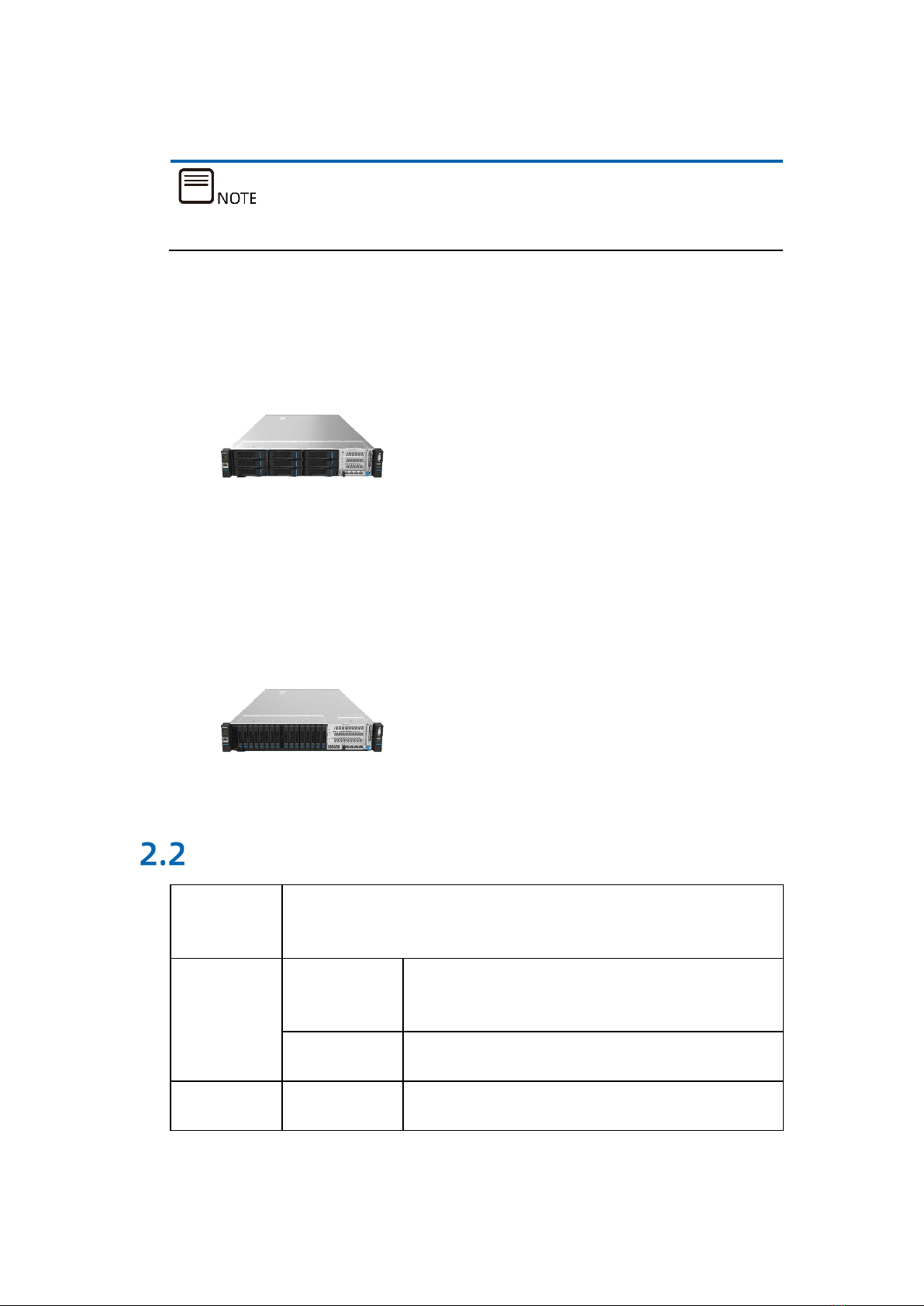
2.1.2 9 × 3.5” Configuration
A 3.5” drive tray can accommodate 3.5”/2.5” drives.
9 front 3.5”/2.5” SAS/SATA drives are supported, as shown below.
Figure 2-1 9 × 3.5” Configuration
2.1.3 16 × 2.5” Configuration
Figure 2-2 16 × 2.5” Configuration
Features and Specifications
Time to
Market 2021
Processor
Type Intel®Xeon®Scalable processors (up to two CPUs
with a TDP of 270 W)
Interfaces 2
Chipset Type C621-A

7
DIMM
Type DDR4 Registered, NVDIMM, and Barlow Pass
Slots 32
Total Capacity Up to 2 T with 64 G per module (excluding BPS)
I/O Port
USB Port 2 USB 3.0 ports
VGA Port 1 front VGA port
Serial Port 1 front serial port
UID LED 1 rear UID button with LED
Display
Controller Controller Type
Integrated in Aspeed 2500 chip, with a maximum
resolution of 1280 × 1024
SAS
Backplane
SAS 3.0
backplane Supports hot-swap SAS/SATA/NVMe drives
NIC NIC Controller Mainboard supports standard OCP/PCIe cards
Management
Chip
Management
Chip
Integrated with a separate 1000 Mbps NIC for
remote IPMI management
Expansion
Slot
PCIe
expansion
slots
3 FHHL slots: 1 × PCIe x16 + 2 × PCIe x8 (full-
height slots are only available for the
configuration of 2.5” drives and PCIe x16)
4 FHHL slots: 2 × PCIe x16 + 2 × PCIe x8
Up to 1 OCP 3.0 NIC
Drive Type 2.5”/3.5” SAS/SATA/NVMe drives. Please refer to
the actual server model.
External Drive
USB Drive External USB drives
TF Card None
Power Supply Specifications Output power of 800 W/1300 W or above in a
single- or dual-power supply configuration; two

8
redundant (1+1) PSUs with PMBus support and
Node Manager 4.0
Power Input See the power input value labeled on the
nameplate of the chassis outer surface.
Physical
Specifications
Packaging
(h × w × d) 780 mm in length: 295 mm × 651 mm × 1031 mm
Chassis
(h × w × d) 780 mm in length: 87 mm × 435 mm × 780 mm
Weight
At full configuration of 9 × 3.5” bays (9 drives)
Chassis weight: 25 kg
Gross weight: 33 kg (Chassis + Package +
Rails + Accessory Box)
At full configuration of 16 × 2.5” bays (16 drives)
Chassis weight: 22 kg
Gross weight: 30 kg (Chassis + Package +
Rails + Accessory Box)
Environment
Parameters
Temperature
Operating: 10°C to 35°C (50°F to 95°F)
(ASHRAE CLASS A2 compliant)
Storage: -40℃ to +70℃ (-40℉ to +159℉)
Rate of change: ≤ 20℃/h (68℉/h)
Humidity
Operating: 5%- 90%RH
Storage: 5%- 95%RH
Rate of change: ≤ 40% RH/h
Altitude
Operating: 0 - 3050 m
Storage: 0 - 12,000 m
Vibration
Operating: 5 - 500 Hz, 0.21 Grms (3 axes)
Storage: 5 - 500 Hz, 2.20 Grms (3 axes)
Shock
Operating: 2 G half-sine wave on a 11-ms
interval along the positive and negative
X-/Y-/Z-axis

9
Storage: 40 G square wave at 156”/sec along
the positive and negative X-/Y-/Z-axis
Power Efficiency
Table 2-1 Platinum Power Supply
Vendor
Module @10%
Load
@20%
Load
@50%
Load
@100%
Load
PF@50%
Load
Rated
Power
Delta
DELTA_M_DPS-
800AB-
58A_800W_1U_P
88% 94% 94% 91% 98% 800 W
DELTA_M_DPS-
1300AB-
27A_1300W_1U_P
88% 94% 94% 91% 98% 1300 W
DELTA_M_DPS-
1600AB-
45A_1600W_1U_P
88% 94% 94% 91% 98% 1600 W
DELTA_M_DPST-
2030AB
F_2000W_1U_P
88% 94% 94% 91% 98% 2000 W
Great
Wall
G_M_GW-
CRPS800N2W_800
W_1U_P_S
88% 94% 94% 91% 98% 800 W
G_M_GW-
CRPS1300D2W_13
00W_1U_P
88% 94% 94% 91% 98% 1300 W
G_M_GW-
CRPS1600D2W_16
00W_1U_P
88% 94% 94% 91% 98% 1600 W
G_M_GW-
CRPS2000DW_200
0W_1U_P
88% 94% 94% 91% 98% 2000 W
Liteon
LO_M_PS-2801-
22L1_1U_P
88% 94% 94% 91% 98% 800 W
LO_M_PS-2132-
11L1_800W_1U_P
88% 94% 94% 91% 98% 1300 W
LO_M_PS-2162-
15L1_1300W_1U_P
88% 94% 94% 91% 98% 1600 W
Note: Efficiency was tested under the AC input voltage of 230 VAC/50 Hz (according to the 80 PLUS®
Standard)

10
Table 2-2 EU Regulation 2019/424 Server configurations
EU Regulation 2019/424
Server configurations
High-end performance
configuration
Low-end
performance
configuration
(h)idle state power 218.3 183.1
(i)list of all components for
additional idle power
allowances, if any (additional
PSU, HDDs or SSDs, additional
memory, additional buffered
DDR channels, additional I/O
devices);
393.68 184.53
(j)maximum power, expressed
in Watts and rounded to the first
decimal place;
612.1 493.7
(k)declared operating condition
class, as detailed in Table 6;
A2
A2
(l)idle state power (Watts) at the
higher boundary temperature
of the declared operating
condition class;
219 185
(m)the active state efficiency
and the performance in active
state of the server;
43.1 27.4
Table 2-3 List of components for additional power allowance
(i) List of components for additional power
allowance
High-end
performance
configuration
Low-end
performance
configuration
CPU
Performance
1 socket: 10 × Perf CPU W
2 socket: 7 × Perf CPU W
150.08 79.17
Additional
PSU
10 W per PSU 10 10
HDD or SSD 5,0 W per HDD or SSD
10 10
Additional
memory
0,18 W per GB 183.6 45.36
Additional
buffered DDR
channel
4,0 W per buffered DDR
channel 32 32

11
(i) List of components for additional power
allowance
High-end
performance
configuration
Low-end
performance
configuration
Additional I/O
devices
< 1 Gb/s: No Allowance
= 1 Gb/s: 2,0 W/Active Port
> 1 Gb/s and < 10 Gb/s: 4,0
W/Active Port
≥ 10 Gb/s and < 25Gb/s:
15,0 W/Active Port
≥ 25 Gb/s and < 50Gb/s:
20,0 W/Active Port
≥ 50 Gb/s 26,0 W/Active
Port
88
Total additional idle state power allowed 393.68 184.53

12
Component Description
Front Panel Components
3.1.1 9 × 3.5” Bays
Figure 3-1 9 × 3.5” Configuration at Front Panel
# Item
1 Power Button
2 Drive Bay × 9
3 PCIe0 Slot
4 PCIe1 Slot
5 PCIe2 Slot
6 VGA Port
7 USB 3.0 Port × 2
8 Mounting Ear Handle
9 OCP 3.0 NIC
10 RJ45 Network Interface
11 UID Button
12 System Status LED
1 2 3 4 5 6 7
8
9
8
10
12
11
Table of contents
Other Inspur Server manuals

Inspur
Inspur NF5486M5 User manual

Inspur
Inspur Yingxin NX 5440 User manual

Inspur
Inspur NE5260M5 User manual

Inspur
Inspur NF5888M5 User manual

Inspur
Inspur NE5260M5 User manual

Inspur
Inspur NF5280M6 User manual

Inspur
Inspur NF8480M5 Instruction Manual

Inspur
Inspur NF5220 User manual

Inspur
Inspur i24 User manual

Inspur
Inspur Yingxin NF5280M2 User manual

Inspur
Inspur TS860M5 User manual

Inspur
Inspur NF5180M4 User manual

Inspur
Inspur NX5460M4 User manual

Inspur
Inspur NF3120M5 User manual

Inspur
Inspur NF8480M5 User manual

Inspur
Inspur Yingxin User manual

Inspur
Inspur i48M6 User manual

Inspur
Inspur Yingxin User manual

Inspur
Inspur SA5212M4 User manual

Inspur
Inspur NF5266M5 User manual


 Quickspecs")


