Inspur SA5212M4 User manual
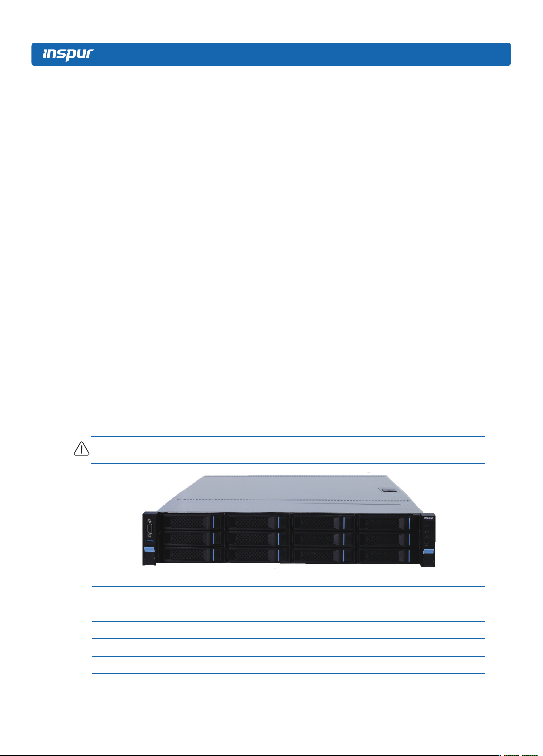
© Copyright Inspur 2016. All rights reserved.
No part of this document may be reproduced or transmitted in any form or by any means
without prior written consent of Inspur.
The information in this manual is subject to change without notice.
Inspur is the registered trademark of Inspur. All the other trademarks or registered
trademarks mentioned in this manual are the property of their respective holders.
Edition: 1
Sep 2016

Abstract
This manual contains technical information such as specifications, hardware
operations, software configuration, fault diagnosis, etc. that are relevant to the
maintenance and operation of this server.
It is recommended that server installation, configuration, and maintenance is
performed by experienced technicians only.
Target Audience
This manual is intended for:
●Technical support engineers
●Product maintenance engineers
●Technicians
Warnings:
This manual introduces the server’s technical features, system installation and
setup, which will help the user to understand how best to utilize the server and all its
functionalities.
1.For your safety, please do not disassemble the server’s components arbitrarily.
Please do not extend conguration or connect other peripheral devices arbitrarily. If
needed, please contact Inspur for our support and guidance.
2.Before disassembling the server’s components, please be sure to disconnect all
the power cords connected to the server.
3.BIOS and BMC setup is a signicant factor in correctly conguring your server. If
there are no special requirements, it is suggested to use the default values and not
alter the parameter settings arbitrarily.
4.Please use the driver shipped with the server or provided in Inspur ofcial website,
if you use non-Inspur driver, it may cause compatibility issues and affect the normal
use of the product, Inspur will not assume any responsibility or liability.
The manufacturer is not responsible for any damages, including loss of prots,
loss of information, interruption of business, personal injury, and/or any damage or
consequential damage without limitation, incurred before, during, or after the use of
our products.

Table of Content
1 Safety Instructions ...........................................................................................................1
2 Product Specication Introduction ...................................................................................6
2.1 Introduction...................................................................................................................6
2.2 Features and Specication ...........................................................................................6
3 Component Identication.................................................................................................9
3.1 3.5×12 Disk Position ....................................................................................................9
3.2 Hard Drive Bay LEDs ...................................................................................................9
3.3 Rear Panel....................................................................................................................10
3.4 System Board Components..........................................................................................11
3.5 System Board Jumper Introduction ..............................................................................13
4 Operations.......................................................................................................................14
4.1 Power up the Server.....................................................................................................14
4.2 Power down the Server ................................................................................................14
4.3 Extend the Server from the Rack..................................................................................14
4.4 Remove the Access Panel ...........................................................................................15
4.5 Install the Access Panel ...............................................................................................16
4.6 Remove the Air Bafe...................................................................................................16
5 Setup ...............................................................................................................................18
5.1 Optimum Environment..................................................................................................18
5.2 Rack Warnings .............................................................................................................21
5.3 Identifying the Contents of the Server Shipping Carton................................................21
5.4 Installing Hardware Options .........................................................................................22
5.5 Installing the Server into the Rack................................................................................22
5.6 Installing the Operating System....................................................................................23

6 Hardware Options Installation .........................................................................................24
6.1Processor Option...........................................................................................................24
6.2 Memory Options ...........................................................................................................26
6.3 Hot-plug Hard Drive Option ..........................................................................................27
6.4 Removing a Hot-plug Hard Drive..................................................................................28
6.5 Redundant Hot-plug Power Supply Option...................................................................29
6.6 PCIE Expansion Card Replacement ............................................................................30
6.7 Air Bafe Replacement.................................................................................................30
7 Cabling ............................................................................................................................31
8 BIOS Setup......................................................................................................................32
8.1 System BIOS Setup Methods.......................................................................................32
8.2 BIOS Conguration.......................................................................................................33
8.3Firmware Update...........................................................................................................67
9 BMC Settings ..................................................................................................................71
9.1 Introduction...................................................................................................................71
9.2 Functional Modules ......................................................................................................72
9.3 Web Interface Introduction ...........................................................................................73
9.4 Remote Control ............................................................................................................76
9.5 Power Supply and Heat Radiation................................................................................78
9.6 BMC Conguration .......................................................................................................79
9.7 Logs..............................................................................................................................82
9.8 Fault Diagnosis.............................................................................................................83
9.9 System Maintenance ....................................................................................................84
9.10 Command Line Function Introduction.........................................................................85
9.11 Time Zone Table ........................................................................................................90
10 Common Faults, Diagnosis and Troubleshooting..........................................................92
10.1 Common Faults ..........................................................................................................92
10.2 Diagnosis and Troubleshooting Instructions...............................................................93

11 Battery Replacement .....................................................................................................96
12 Regulatory Compliance Notices ....................................................................................97
12.1 Regulatory Compliance Identication Numbers .........................................................97
12.2 Federal Communications Commission Notice............................................................97
12.3 Cables ........................................................................................................................98
12.4 European Union Regulatory Notice ............................................................................98
12.5 Disposal of Waste Equipment by Users in the European Union.................................98
12.6 Korean Notice.............................................................................................................99
12.7 Chinese Notice ...........................................................................................................99
12.8 Battery Replacement Notice.......................................................................................99
13 Electrostatic Discharge..................................................................................................101
13.1 Preventing Electrostatic Discharge.............................................................................101
13.2 Grounding Methods to Prevent Electrostatic Discharge.............................................101
14 Inspur Support Guide ....................................................................................................102

1
Safety Introduction
1 Safety Instructions
Warning: Please be advised to follow the instructions below for safety. Failure to do
so could result to potential dangers that may cause property loss, personal injury or
death.
1. The power supplies in the system may produce high voltages and energy
hazards that may cause personal injury. For your safety, please do not attempt
to remove the cover of the system to remove or replace any component without
assistance provided by Inspur. Only service technicians trained by Inspur are
authorized to remove the cover of the host, and to remove and replace internal
components.
2. Please connect the equipment to the appropriate power supply. Use only power
supplies with the correct voltage and electrical specications according to the
label. To protect your equipment from damages caused by a momentary spike
or plunge of the voltage, please use relevant voltage stabilizing equipment, or
uninterruptible power supplies.
3. If you must use an extension cable, please use a three-core cable with properly
grounded plugs. Observe extension cable ratings. Ensure that the total rating of
all equipment plugged into the extension cable does not exceed 80 percent of
the ratings limit for the extension cable.
4. Please be sure to use the power supply components that come with the server,
such as power lines, power socket (if provided with the server) etc. For your
safety, please do not replace power cables or plugs randomly.
5. To prevent electric shock dangers caused by leakage in the system, please
make sure that the power cables of the system and peripheral equipment are
correctly connected to the earthed/grounded power socket. Please connect
the three-core power line plug to the three-core AC power socket that is well
earthed and easy to access. Be sure to use earthing /grounding pin of power
lines and do not use the patch plug or the earthing/grounding pin unplugged
with cables. In the case that the earthing/grounding conductors are not installed
and it is uncertain whether there are appropriate earthing/grounding protections,

2
please do not use or attempt to operate the equipment. Contact and consult an
electrician.
6. Please do not push any objects into the openings of the system. Doing so may
cause re or electric shock.
7. Please place the system far away from the cooling plate and heat sources, and
be sure not to block the air vents.
8. Please be sure not to scatter food or liquid in the system or on other
components, and do not use the product in humid or dusty environments.
9. Using an incompatible battery may cause explosion. When battery replacement
is required, please consult the manufacturer rst, and choose batteries of the
same or equivalent type. Do not disassemble, crush, puncture the batteries or
make the external connection point short circuit, and do not expose them in
the environment over 60°C. Never throw batteries into re or water. Please do
not attempt to open or repair the batteries. Dispose of used batteries according
to instructions. For battery recycling, please contact the local waste recycling
center.
10. Before installing equipment into the rack, please install all front and side
stabilizers on the independent rack rst. Please install the front stabilizers rst, if
connecting with other racks. Please install stabilizers before installing equipment
into the rack. Failure to install the corresponding stabilizers before installing
equipment into the rack may cause the cabinet to tip over, possibly resulting to
severe injury. After installing the equipment and other components into the rack,
only one component can be pulled out from the rack through its sliding part at
one time. Pulling out several components at the same time may cause the rack
to turn over, resulting to serious personal injury.
11. A minimum of two people are required to safely move a rack. The racks
are extremely awkward and heavy, moving them without adequate, trained
personnel could result in severe injury or death.
12. It is prohibited to directly short-circuit the copper busbar. Please do not touch the
copper busbar when the rack is powered on.
13. This is Class A product, and may cause radio interference. In such case, users
may need to take necessary measures to mitigate the interference.

3
Safety Introduction
14. The equipment is intended for installation in a Restricted Access Location.
Note: The following considerations may help avoid the occurrence of problems that
could damage the components or cause data loss, etc.
1. In the event of the following, please unplug the power line plug from the power
socket and contact Inspur’s customer service department:
1) The power cables, extension cables or power plugs are damaged.
2) The products get wet.
3) The products have fallen or have been damaged.
4) Other objects have fallen into the products.
5) The products do not or are unable to function normally even when attempting to
operate according to the instructions.
2. If the system becomes wet or damp, please follow these steps:
1) Power off the equipment, disconnect them with the power socket, wait for 10 to
20 seconds, and then open the host cover.
2) Move the equipment to a well-ventilated place to dry the system at least for 24
hours and make sure that the system is fully dried.
3) Close the host cover, reconnect the system to the power socket, and then power
on.
4) In case of operation failure or other abnormal situations, please contact Inspur
and get technical support.
3. Pay attention to the position of system cables and power cables-avoid placing
wires in high foot trafc locations. Please do not place objects on the cables.
4. Before removing the host cover, and/or touching the internal components,
please allow for the equipment to cool rst. To avoid damaging the mainboard,
please power off the system and wait for ve seconds, and then remove the
components from the mainboard and/or disconnect the peripheral device from
the system. Please remember that only service technicians trained by Inspur are
authorized to remove the cover of the host, and to remove and replace internal
components.
5. If there is modem, telecom or LAN options installed in the equipment, please
pay attention to the followings:

4
1) In the case of thunder and lightning, please do not connect or use the modem.
2) Never connect or use the modem in a damp environment.
3) Never insert the modem or telephone cables into the socket of network interface
controller (NIC).
4) Before unpacking the product package, installing internal components, touching
uninsulated cables or jacks of the modem, please disconnect the modem
cables.
6. In order to prevent electrostatic discharge from damaging the electronic
components in the equipment, please pay attention to the followings:
1) Please remove any static electricity on your body before dismounting or
touching any electronic component in the equipment, to prevent the static
electricity from conducting itself to the sensitive components. You may remove
the static electricity on the body by touching the metal earthing objects (such as
the unpainted metal surface on the rack).
2) Please do not take electrostatic sensitive components that are not ready to be
installed for application out of the antistatic package materials.
3) While working, please touch the earthing conductor or the unpainted metal
surface on the cabinet regularly to remove any static electricity from the body
that may damage the internal components.
7. Upon receiving the proper authorization from Inspur and dismounting the
internal components, please pay attention to the following:
1) Switch the system power supply off and disconnect the cables, including all
connections of the system. When disconnecting the cables, please hold the
connector of the cables and slowly pull the plugs out. Never pull on the cables.
2) The products need to completely cool down before dismounting the host cover
or touching the internal components.
3) During the dismounting process, avoid making large movement ranges to
prevent damage to the components or scratching arms.
4) Handle components and plug-in cards with care. Please do not touch the
components or connection points on the plug-in cards. When handling the
plug-in cards or components, firmly grab the edges of the plug-in cards and
components, and/or their metal xed supports.
8. During the process of rack installation and application, please pay attention to

5
Safety Introduction
the followings:
1) After the rack installation is finished, please ensure that the stabilizers have
been xed to the rack and supported to ground, and the weight of the rack is
rm on ground.
2) Always load from the bottom up, and load the heaviest items rst.
3) When pulling out the components from the rack, apply slight force to keep the
rack balanced.
4) When pressing down the release latch and the rail of components is sliding,
please be careful; as the sliding may hurt your ngers.
5) Do not overload the AC power supply branch circuits in the rack. The total load
of the rack should not exceed 80% of the ratings of the branch circuits.
6) Ensure that components in the rack have good ventilation conditions.
7) When repairing components in the rack, never step on any other components.

6
2 Product Specication Introduction
2.1 Introduction
This type is a kind of server product developed independently. It adopts Intel
Grantley-EP platform, and uses Wellsburg chip set. It supports two mainstream
Intel Xeon E5-26** V4(or E5-26** V3) series processors. It supports 16 DIMM
DDR4 memory, reaching up to 2400MHz. It supports ECC Registered and multiple
senior memory redundancy function.It supports up to 2.5” x 16 SAS/SATA/SSD hot-
plugging hard disks or 3.5” x 12 SAS/SATA/SSD hot-plugging hard disks.
Mainboard integrates Gigabit network cards of high performance, and supports
network advanced features. Mainboard integrates BMC/KVM chips. 5 PCI-Express
expansion slots available.Supports SAS 3.0 (12Gb/s) or SAS Raid cards, and
implements exible SAS/SAS RAID solutions. Modular design on components such
as structure, storage, PCI expansion, power supply and fan etc. Energy-saving
and noise reduction design, equipped with PMbus power supply of high efciency,
supports DPNM function, and implements energy saving and consumption reducing.
Supports 12 front set 3.5/2.5 inches SAS/SATA/SSD hard disks, and appearances of
them are as shown in the following gure.
Note: The 3.5 inches hard disk bracket could be used to hold a 3.5/2.5 inches hard disk.
2.2 Features and Specication
Processor
Processor Type Intel dual-way Xeon E5-26** V4(or E5-26** V3) Series (supports up to two 145W)
Interface Two Socket-R3 slots.
Chipset
Chipset Type PCH C610(Wellsburg)

7
Product Specication Introduction
Memory
Memory Type DDR4 ECC RDIMM/LRDIMM memory
Single Inline
Memory Module
Qty.
16
Memory Volume It supports up to 1024GB (64GB for single)
I/O Interface
USB Interface 2 rear set USB 3.0 interfaces, and 2 built-in USB 3.0 interfaces
Display Interface 1 front set VGA interface
1 rear set VGA interface
Serial Interface 1 built-in serial port
ID Indicator
Interface 1 ID indicator (blue) and its press button
Display Controller
Controller Type A speed 2400 integrated in chip, with max. resolution supporting 1280*1024
SAS Backplane
SAS3.0 backplane It supports hog-plugging SAS/SATA/SSD hard disks.
Network Card
Network Card
Controller
The mainboard optionally integrates 1 Intel I350 double gigabit or four gigabit
net card, and provides two or four 1000M self-adapting RJ45 net ports;
The mainboard optionally integrates 1 Intel 82599 single-port or double-port
10 gigabit net card, and provides one or two 10 gigabit SFP+Net Card(s).
Management Chip
Management Chip It integrates 1 independent 1000Mbps network interface, which is used in
IPMI remote management.
PCI Extension Slot
Mainboard:
1 onboard PCI Express 3.0 x24 slot (used to support PCI-E Riser, which
could not adapt to external cards); 3 vertically inserted PCIE slots;
When there’s one single CPU is in the system:
It could support 1 PCIE x8+x1 slot (able to support network sub card of
management function).
It could support 1 PCIE x8 (in x16 Slots).
When there’re double CPUs in the system:
It could support 1 vertically inserted PCIE x8+x1 slot (able to support
management function network card).
It could support 1 vertically inserted PCIE x8 (in x16 Slots)
It could support 1 vertically inserted PCIE x16 (in x16 Slots)
Via installing a Riser card connecting to a full height and half height card, it could
support 1 vertically inserted PCIE x8 (in x8 Slots) and 1 PCIE x16 (in x16 Slots);
Hard Disk
Hard Drive Type Front set 2.5/3.5 inch SAS, SATA and SSD hard disks; Up to 4 rear set SATA and
SSD hard disks could be supported. (Subject to actual type you purchased)

8
External Storage Driver
CD Driver External USB CD drive.
Drive U Disk Optional drive U disk.
Power Supply
Specification
Output power of sing/Double power 550W/800W and above; 1+1
redundancy; 2 power modules; it supports PMBus power supply, and
implements Node Manager 3.0 function.
Power Input Please refer to power input on nameplate tag of the host.
Physical Specification
External Dimension
of Package 651 width × 307 height × 971 depth (unit: mm)
Host Size 447 width × 87 height × 720 depth (unit: mm)
Product Weight
Standard configuration (3 hard disks)
Host weight: 19.5kg;
Gross weight: 32kg. (Gross weight includes: Host + Packing Box + Rail +
Parts Kit)
Full configuration (24 hard disks)
Host weight: 25.8kg;
Gross weight: 35.55kg. (Gross weight includes: Host + Packing box + Rail +
Parts box)
Environment Parameters
Working
Environment
Temperature
10℃ -35℃
Storage &
Transportation
Temperature
-40℃ -60℃
Working Humidity 35% -80% relative humidity
Storage &
Transportation
Humidity
20% -93% (40℃ ) relative humidity

9
Component Identication
3 Component Identication
3.1 3.5×12 Disk Position
Number Module Name
1 Front set VGA interface
2 Front set USB 3.0 interface
3Securing buckle of server and cabinet
4 Front set hard disk slot
5 Server switch button
6 ID light and button
7 System fault indicator button
8 LCD liquid crystal management module interface
3.5×12 disk position hard disk sequence diagram
3.2 Hard Drive Bay LEDs
Number Module Name Description
1 Hard disk activity status indicator Constant green: Normal
Flashing green: Hard disk is reading and writing
2 Hard disk fault alarming indicator
Constant red: Hard disk fault
Constant blue: Hard disk positioning
Constant pink: In coordination with RAID rebuilding

10
3.3 Rear Panel
Number Module Name
1 Rear set 2.5 inch hard disk slot
2 PCIE slot (half height)
3 PCIE slot (full height)
4 Power supply 0
5 Power supply 1
6 10 Gigabit net card interface
7 BMC reset button
8 ID light and button
9 Gigabit net card interface
10 VGA interface
11 USB3.0 interface
12 IPMI management interface

11
Component Identication
3.4 System Board Components
Number Module Name
1 Memory slot (corresponding with CPU0)
2 CPU0
3 Memory slot (corresponding with CPU1)
4 CPU1
5 GPU Power supply interface
6 System fan interfaces (8 interfaces in all)
7 I2C interface
8 GPIO interface
9 IPMB interface
10 SATA interfaces (6)

12
Number Module Name
11 CLEAR CMOS jumper
12 TCM interface
13 COM interface
14 sSATA interfaces (4)
15 Front set USB 3.0 interface
16 Built-in USB 3.0 interface
17 Front set VGA interface
18 IPMI management interface / rear set USB 3.0 interface (2)
19 PCIEx24 slots (corresponding with CPU1)
20 Rear set VGA interface
21 Debug light
22 Gigabit network port
23 ID light and button
24 BMC Reset button
25 10 Gigabit net port
26 PCIEx16 slots (corresponding with CPU1)
27 PCIEx8 (corresponding with CPU0)
28 PCIEx8 (in x16 slots corresponding with CPU0)
29 Mainboard handle
30 PSU1
31 PSU0
32 Power interface (4 port)
33 Power interface (8 port)
34 Front control panel interface
35 LSI 3008 HDminiSAS interface
36 LSI 3008 SAS Key

13
Component Identication
3.5 System Board Jumper Introduction
See [2.5 Mainboard Layout] for jumper positions.
Clear CMOS Jumper Introduction
Jumper No. Function Description Jumper Functions
CLR_CMOS CMOS clear jumper Short-circuit pin1-2, to restore normal status; short-
circuit pin2-3, to clear CMOS.
Note:
It is required to shut down the system, as well as disconnect power supply during
CMOS cleaning, and hold for 5 seconds after short-circuiting Pin2-3; then short-
circuit Pin1 and Pin2 of CLR_CMOS jumper with a jumper cap (the default status), to
restore its original status.

14
4 Operations
4.1 Power up the Server
Insert the power cord plug, then press the Power On button.
4.2 Power down the Server
WARNING: To reduce the risk of personal injury, electric shock, or damage to the
equipment, remove the power cord to remove power from the server. The front panel
Power On button does not completely shut off system power. Portions of the power
supply and some internal circuitry remain active until AC power is removed.
IMPORTANT: If installing a hot-plug device, it is not necessary to power down the
server.
1. Back up the server data.
2. Shut down the operating system.
3. Disconnect the power cords.
The system is now without power.
4.3 Extend the Server from the Rack
1. Pull down the quick release levers on each side of the server.
2. Extend the server from the rack.
WARNING: To reduce the risk of personal injury or equipment damage, be sure that
the rack is adequately stabilized before extending a component from the rack.

15
Operations
3. After performing the installation or maintenance procedure, slide the server back
into the rack, and then press the server rmly into the rack to secure it in place.
WARNING: To reduce the risk of personal injury, be careful when sliding the server
into the rack. The sliding rails could pinch your ngers.
4.4 Remove the Access Panel
WARNING: To reduce the risk of personal injury from hot surfaces, allow the drives
and the internal system components to cool before touching them.
CAUTION: For proper cooling do not operate the server without the access panel,
air bafe, or fan installed. If the server supports hot-plug components, minimize the
amount of time the access panel is open.
Table of contents
Other Inspur Server manuals

Inspur
Inspur SA5112M4 User manual

Inspur
Inspur Yingxin NX 5440 User manual

Inspur
Inspur NE5260M5 User manual

Inspur
Inspur NF5280M6 User manual

Inspur
Inspur NF5468M6 User manual

Inspur
Inspur OS User manual

Inspur
Inspur NF5266M6 User manual

Inspur
Inspur i48M6 User manual

Inspur
Inspur NF5180M6 User manual

Inspur
Inspur NF5466M5 User manual

Inspur
Inspur NF5266M5 User manual

Inspur
Inspur NF3180A6 User manual

Inspur
Inspur NF5468M5 User manual

Inspur
Inspur NF3120M5 User manual

Inspur
Inspur NF5180M5 User manual

Inspur
Inspur NF5288M5 User manual

Inspur
Inspur NF5448A6 Quick reference guide

Inspur
Inspur 3408 Series Instruction sheet

Inspur
Inspur NX5460M5 User manual

Inspur
Inspur NP5570M4 User manual