manuals.online logo
Brands
  1. Home
  2. •
  3. Brands
  4. •
  5. Inspur
  6. •
  7. Server
  8. •
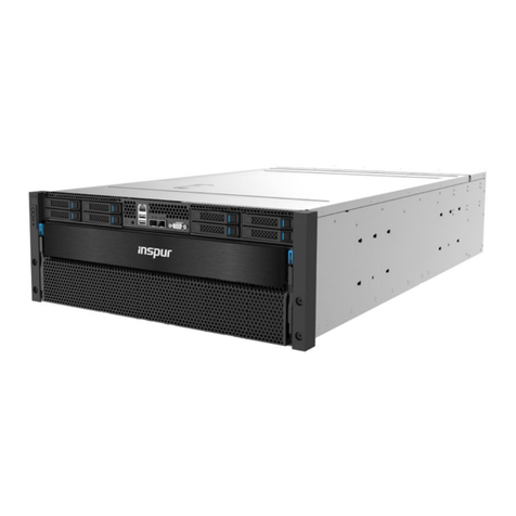
  9. Inspur i48M6 User manual

Inspur i48M6 User manual

X01500A000000000
Warnings!
Please keep this document for future reference.
15kg
30kg
50kg
Watch out for the scratches that may be caused by the cabinet, chassis or rails.
Be aware of electric shock when installing the servers into the cabinet in use.
●For servers of 4U form factor or higher, at least 4 people are needed for installation.
●DO NOT block the vents on the server during installation, especially the vents on the front
and rear of the server.
●Remove the protective film from the chassis before installing servers into the rack.
●For proper ventilation, leave a minimum space of 15cm between two servers.
●For easy access of the front and rear ports and cabling, leave a minimum space of 70mm
between the front side of the server and the inner side of the cabinet’s front door, and
150mm between the rear side of the server and the inner side ofthe cabinet’s rear door.
●Always keep the air baes in place to ensure proper air flow and avoid air turbulence in the
server room.
●Installation must comply with local and regional electrical regulations. To reduce the risk of
personalinjury, fire, or damage to the server, DO NOT overload the AC supply that provides
power to the rack.
●Servers can only be deployed in dedicated cabinets with ventilation holes or specialized
cooling cabinets to avoid server failure from overheating as they are high power appliances.
●In case of multiple-server deployment, always load from bottom to top and place the heavier
server on the lower bay.
●DO NOT install devices beyond the cabinet’s load-bearing capacity, power supply capacity
and heat dissipation capacity.


For devices ≥ 15kg, it requires at least 2 people.
For devices ≥ 30kg, it requires at least 3 people.
For devices ≥ 50kg, it requires at least 4 people.
Rack-Mounted Server
Installation Guide
V1.0
Rack-Mounted Server Installation Guide
V1.0
5.A bracket is needed when the server is equipped with nodes. Install six
floating nuts into the holes next to the bottom of the rails, and then
secure the bracket to the rack with 6 screws. Make sure that the top of
the bracket stays against the bottom of the rails.
4.Repeat Step 1-3 for the other rail and the other stopper.
Note: The two rails must be installed at the same height.
The rails are applicable for square-hole (9.2*9.2 mm, 9.5*9.5mm) and
round-hole (Ø 7.1mm) racks.
Rail-Kit Components
Rails, Stoppers , Screws: M5x8 Phillips head screw (×4)
Installing the Rails
1.Align the pins on the rear bracket to the desired position of the back of the
rack. Press the locking latch as indicated by arrow ①, and then insert the
pins as indicated by arrow ②until the pins are fully engaged.
2.Follow Step 1 to install the front bracket to the front of the rack.
Note: The front end and the rear end of the rail must be installed at the same
height.
3.Install the two floating nuts into the post holes above the rear end of the
rail. Hold the stopper, and then insert and tighten the two M5x8 Phillips
head screws. Make sure the space between the top of the stopper and
the bottom of the rail is 4U.
Note: You may use either stopper 1 or stopper 2 for stopper installation.
2
Stopper
Option 1
Stopper
Option 2
Stopper 1 Installation
Use square nuts on square-hole posts.
Use U-nuts on round-hole posts.
Stopper 2 Installation
Note: Two washers are
needed for square-hole
posts.
Rear BracketFront Bracket Rail
2
1
2
1
1
4U
①Pull and rotate the plunger on the lifting handle clockwise or
nticlockwise. Make sure the plunger does not spring back.
②Align and attach the 5 T-standos on the lifting handle to the
eyholes on the side of the server. Push the handle until the
T-standos slide nto the smaller holes. Rotate and release the
plunger until it springs ack into the chassis.
③Refer to steps ①and ②to install the other 3 lifting handles.
2.Hold the lifting handles to lift the server up onto the rails. Refer to
the installation procedure to remove the 4 lifting handles.
3. Slide the server all the way into the rack and tighten the captive
screws in the mounting ears.
Note: Keep the removed lifting handles properly for future use.
Installing the Server
1.Install the lifting handles.
Plunger
T-standoff
Other Inspur Server manuals

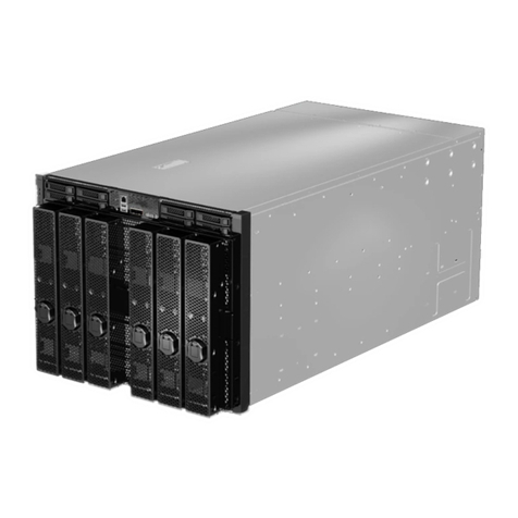
Inspur NF5488A5 User manual

Inspur

Inspur NF5488A5 User manual

Inspur Yingxin NF5280M2 User manual

Inspur

Inspur Yingxin NF5280M2 User manual

Inspur SA5112M4 User manual

Inspur

Inspur SA5112M4 User manual

Inspur NP3060 User manual

Inspur

Inspur NP3060 User manual

Inspur NF8480M5 User manual

Inspur

Inspur NF8480M5 User manual

Inspur Yingxin User manual

Inspur

Inspur Yingxin User manual

Inspur NF8260M6 User manual

Inspur

Inspur NF8260M6 User manual

Inspur NF3120M5 User manual

Inspur

Inspur NF3120M5 User manual

Inspur NX5760M3 User manual

Inspur

Inspur NX5760M3 User manual

Inspur NE5260M5 User manual

Inspur

Inspur NE5260M5 User manual

Inspur NE5260M5 User manual

Inspur

Inspur NE5260M5 User manual

Inspur NF5180M4 User manual

Inspur

Inspur NF5180M4 User manual

Inspur Yingxin User manual

Inspur

Inspur Yingxin User manual

Inspur NF8260M5 User manual

Inspur

Inspur NF8260M5 User manual

Inspur NF5266M6 User manual

Inspur

Inspur NF5266M6 User manual

Inspur NF5468M6 User manual

Inspur

Inspur NF5468M6 User manual

Inspur NX8840 User manual

Inspur

Inspur NX8840 User manual

Inspur Yingxin NX 5440 User manual

Inspur

Inspur Yingxin NX 5440 User manual

Inspur I48 User manual

Inspur

Inspur I48 User manual

Inspur NF5260FM6 User manual

Inspur

Inspur NF5260FM6 User manual

Inspur Yingxin NX5440M4 User manual

Inspur

Inspur Yingxin NX5440M4 User manual

Inspur NF5280M5 User manual

Inspur

Inspur NF5280M5 User manual

Inspur NF5888M5 User manual

Inspur

Inspur NF5888M5 User manual

Inspur 3408 Series Instruction sheet

Inspur

Inspur 3408 Series Instruction sheet

Popular Server manuals by other brands

SMC Sierra Monitor FS-QS-1010 QuickServer Start-up Guide

SMC Sierra Monitor

SMC Sierra Monitor FS-QS-1010 QuickServer Start-up Guide

Acer ALTOS R910 Series user guide

Acer

Acer ALTOS R910 Series user guide

Verizon VMS1100 installation instructions

Verizon

Verizon VMS1100 installation instructions

Lanberg WF01 64 V2 Series user manual

Lanberg

Lanberg WF01 64 V2 Series user manual

Avaya S8700 Series Quick start for hardware installation

Avaya

Avaya S8700 Series Quick start for hardware installation

HP ProLiant BL460c G7 Maintenance and service guide

HP

HP ProLiant BL460c G7 Maintenance and service guide

IBM eserver pSeries 690 Service guide

IBM

IBM eserver pSeries 690 Service guide

Dell POWEREDGE SC440 specification

Dell

Dell POWEREDGE SC440 specification

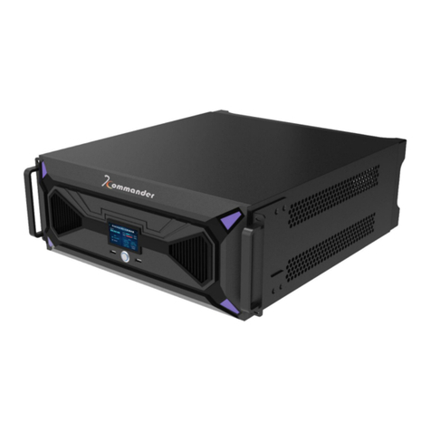
Kommander PS4 user manual

Kommander

Kommander PS4 user manual

LOYTEC L-INX user manual

LOYTEC

LOYTEC L-INX user manual

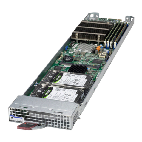
Supermicro MicroBlade MBI-310T-4C2 user manual

Supermicro

Supermicro MicroBlade MBI-310T-4C2 user manual

Toshiba BMS-LSV4E installation manual

Toshiba

Toshiba BMS-LSV4E installation manual

Dell EMC PowerEdge R740 Installation and service manual

Dell EMC

Dell EMC PowerEdge R740 Installation and service manual

Sun Oracle SPARC T3-1 installation guide

Sun Oracle

Sun Oracle SPARC T3-1 installation guide

HP D7171A - NetServer - LPr manual

HP

HP D7171A - NetServer - LPr manual

HP BL10e - HP ProLiant - 512 MB RAM Quickspecs

HP

HP BL10e - HP ProLiant - 512 MB RAM Quickspecs

Asus A33 user manual

Asus

Asus A33 user manual

TYAN GA88-B5631 Service engineer's manual

TYAN

TYAN GA88-B5631 Service engineer's manual

manuals.online logo
manuals.online logoBrands
  • About & Mission
  • Contact us
  • Privacy Policy
  • Terms and Conditions

Copyright 2025 Manuals.Online. All Rights Reserved.