Integral LED ILSTRGBB174E User manual
EN IP65
INSTALLATION INSTRUCTION
Spotless RGB 24V INTEGRAL LED Strip IP65 - 5 Year Warranty
Important Notice
1. This product should be installed according to the instructions in this guide and by a qualied electrical installer. All electrical work must be completed in
accordance with all applicable regulations and laws in the country in which it is being installed. (In accordance with IET regulations in the UK).
2. This product falls in the low voltage Class III circuit category.
3. The LED strip must be installed in sheltered area (indoor or outdoor). The unit is against to water jets and dust. NOT suitable for water immersion.
4. Do NOT install in an environment, which exposes the strip to direct sunlight. The strip will dissipate heat, so it should be installed in a ventilated area.
5. To maintain the IP65 rating after cutting – Compatible silicone sealant and end-caps must be used. Available silicone, entry end-caps and end-caps Pat
ILSTAC176.
6. Always SWITCH OFF the power at the mains when installing, adjusting, cutting or maintaining the LED strip.
7. Observe the correct polarity when connecting to a driver and controller. See Instruction – Section (C).
8. When the LED strip is ON, avoid staring directly at the LED strip.
9. Observe the operating temperature levels of the LED strip: -25° C to +45° C.
10. Ensure the constant voltage 24V LED driver(s) and controller are correctly specied for the area (IP rating) and total connected length of the LED strip used.
11. Do NOT power the strip whilst in the packaging reel to avoid overheating.
12. Always handle the LED strip with care. Do NOT twist or heavily press down on the LED strip and observe the bending rule.
13. Always switch OFF the power supply before cutting or connecting the LED strip.
14. Safely route and secure all wires so that they cannot be pinched or damaged. The driver must be connected to a stable power supply.
Introduction
1. Depending on the installation, you can purchase optional or additional accessories such as connectors, drivers and controllers. Please get in touch with your
supplier or see integral-led.com for accessories options.
2. The strip has a 5-year warranty. Questions? Please get in touch with your supplier or see integral-led.com.
(A) CHOOSING A 24V LED DRIVER
1. The LED strip operates with a 24V constant voltage LED driver. The total length of the strip (check length specication) can be powered directly with one
appropriate LED Driver. LED Drivers are sold separately in a variety of xed wattage options. Ensure the IP rating matches the requirements of the installation.
2. The specication of the LED driver will depend on the total power wattage required by the connected strip(s). The power wattage rating of the LED driver
should be at least 20% higher than the total wattage required of the strip(s) being powered.
• For example, if the strip power is 6W per metre (6W/m) and the total length of all the connected strips is 12m. Total wattage required is 6W x 12 = 72W.
Multiply by 1.2 to give the minimum driver wattage 72W X 1.2 = 86W. A 100W LED driver would be suitable for 12m. It is important to specify the correct LED
driver.
(B) PRE-INSTALLATION GUIDE
1. It is worth taking some time to plan the project for the desired eect before removing the backing tape of the LED strip. The specication, length, mounting
position and distance from an object determines the appearance of the LED strip light and the possibility of using an aluminium prole with a diuser. In
conjunction with the installed position of the LED strip, you will need to consider the safe placement and concealment of the LED driver, wires and power
switch or controller to turn the strip ON and OFF.
2. We recommend that you temporarily experiment with the strip (and holding the strip without removing the backing tape in place by using suitable resealable
tape such as masking tape if required). Safely connect the power supply – you can carefully move the strip to try dierent angles and positions to gain the
desired illumination eect and position. Check for light hot spots, glare, reections and shadows. Take care in measuring the length required before cutting the
strip. Take into account the space needed for connectors.
3. High-power strips should be installed on a surface with sucient cooling capacity to keep the strip within its temperature levels. We recommend installing the
strip in an appropriate aluminium prole or on heat-sink plates for heat dissipation and strip longevity.
4. The surface to which the strip is applied must be stable, clean, dry, smooth, oil & grease-free, and at room temperature- ideally, metal, ceramics, wood and
plastics. On removal of the strip, some damage to paint, wallpaper or other substrates may occur.
5. Avoid stretching, compressing, folding, twisting or bending the strip to less than 50mm.
Product code Voltage IP Rating Length Width Colour Watts/m LEDs/m
ILSTRGBB174E 24V IP65 5m 14mm RGB 14.4W/m 240LEDs/m
WARNING
DO NOT CONNECT THE LED STRIP DIRECTLY TO A MAINS SUPPLY.
THE LED STRIP MUST ONLY BE CONNECTED TO A SUITABLE CONTROLLER AND LED DRIVER. SWITCH OFF MAINS POWER BEFORE INSTALLING THE STRIP.
(C) TYPICAL INSTALLATION CONFIGURATION
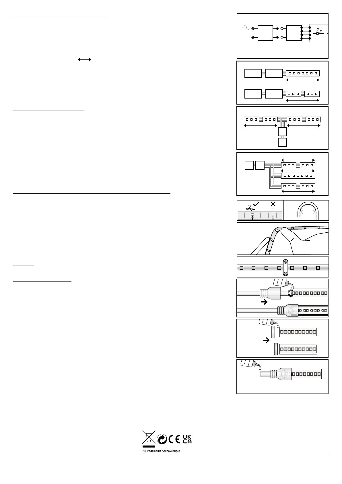
The LED strip is powered by an appropriate LED driver and controller with a suitable wattage output (See Section
A). For controller options, please get in touch with your supplier or see integral-led.com. Ensure the power is
OFF and that the correct polarity is observed when wiring the LED driver. When wiring the receiver of controller
to the strip, always observe polarity for connections to control unit, positive (+) to positive, red (R) to red, green
(G) to green and blue (B) to blue (Fig.1). Additional accessories (sold separately) may be required for complex
congurations. Identify the most appropriate conguration before installation to specify wiring, LED drivers,
controllers and connections.
The maximum powered length ( ) = Total length of LED strip model (3 or 5m).
1. STRAIGHT RUN - a LED driver powers the receiver of controller and rst LED strip.
Additional strips can be connected in series up to the maximum length (Fig.2).
2. POWERED FROM THE CENTRE Power two strip lengths with the driver and the receiver of controller in
the middle, up to the maximum strip length on each side (check length specication) (Fig.3).
3. ARRAY Two or more strips in a parallel connection to the maximum length (Fig.4).
VOLTAGE DROP: If the total length of the connected strips is more than the total maximum powered length,
you may nd that the LEDs furthest away from the driver will be unlit or dimmed. To avoid this, you will need
additional drivers.
(D) INSTALLATION INSTRUCTIONS
1. To ensure a successful installation – please read the precautions, pre-installation and conguration
recommendations and clarify the position and wiring of the strip. Release the strip from the reel.
2. Measure and carefully cut the strip to the required length using an appropriate cutting tool.
Only cut at the cut-marks with the power OFF (Fig.5). See Section (E) to maintain IP rating.
3. The bending diameter of the strip cannot be less than 50mm (Fig.6).
4. Gradually remove the self-adhesive backing tape during installation. Do NOT remove the backing tape
all at once to avoid the strip becoming entangled (Fig.7).
5. Stick the strip to the mounting areas by carefully but rmly pressing down on the strip to activate the
adhesive. Avoid pressing heavily on LEDs and other components.
6. We would recommend using the mounting clips included in the package to secure the installation.
It is the installer’s responsibility to ensure a correct type of screw and tting is used depending on the
mounting substrate. (Fig.8).
7. Once the strip is axed correctly, it is ready to be wired. The power can be turned ON after checking the
supply voltage and wire connections – Please see Section (C).
(E) MAINTAINING IP65 RATING FOR CONNECTIONS AND ENDS OF LED STRIP
1. A compatible silicone sealant is required to maintain the IP65 rating. Wear protective gloves and eyewear
and work on a protected surface (in case of spills) in a well-ventilated area. We recommend that the LED strip
be dried for 24hrs and cured for 7 days before being subjected to water. Ensure the power is OFF and is only
cut at the cut-marks, and a good seal is made.
2. End - Cap – Fill the top of the end-cap with silicone using the nozzle. They carefully ll the end of the strip.
You can use a gloved nger or tool to ensure all gaps are lled (Fig.9).
3. Power Entry End - Cap–Carefully remove enough of the diuser on the strip above the contacts to solder on
wires. Clean the contacts with emery paper and then solder on the power wires. Pay attention to the polarity.
Once the cables have been soldered, safely apply power and controller to the strip to check connections.
Switch OFF the power. Fill the top of the strip with silicone using the nozzle. Apply the end-cap with cable
entry to cover the soldered part. Ensure the gaps around the strip and protruding wires are sealed using a
gloved nger or tool (Fig.10).
CAUTION: Distorting or over bending the strip, cutting at non-cut points, incorrectly powering the strip
or exposing the strip to unsuitable conditions will invalidate the warranty. The strip cannot be returned or
exchange once cut (unless faulty due to parts or workmanship) (your statutory rights remain unaected).
(F) ISSUES AND SOLUTIONS
If you nd the strip is not working, only part of the strip is lit, all or some of the LEDs are intermittently ashing,
or the strip is dim or unevenly lit – Please read the following solutions.
1. Check the LED is compatible – constant-voltage and has the correct voltage – and calculate that the total
wattage of the strips connected to the driver is appropriate. Overvoltage can damage the strip (see Section A).
2. Check all connections, joins, soldering and polarity to the driver, controller and strips for intermittent and
improper connections.
3. Check that the strip is correctly installed and not over-bent.
4. Check the wire lengths between drivers and strips and between strips.
If the wire lengths are too long, shorter or thicker wires may need to be used.
Warranty/Technical &
contact information
are all available at
www.integral-led.com
Integral LED is a division of Integral Memory plc:
Unit 6, Iron Bridge Close, Iron Bridge Business Park,
London, NW10 0UF, UK
Integral Europe BV, 2801 DG, NL
-V
+V
-V
+V
24V LED¹
LEDn
D
24V
DRIVER
DRIVER
DRIVER
L
N
V+
G
R
B
200-240V AC
R
D= Driver
R= Receiver
RECEIVER
DRIVER
RECEIVER
DRIVER
RD
RD
D= Driver
R= Receiver
D= Driver
R= Receiver
RECEIVER
DRIVER
RECEIVER
DRIVER
RD
RD
D= Driver
R= Receiver
D= Driver
R= Receiver
RECEIVER
DRIVER
RECEIVER
DRIVER
RECEIVER
DRIVER
DRIVER
RECEIVER
(Fig.1)
(Fig.2)
(Fig.3)
(Fig.4)
V= Yellow
G= Green
R= Red
B= Blue
(Fig.5) (Fig.6)
>=50mm
(Fig.7)
(Fig.8)
(Fig.9)
(Fig.10)
Table of contents
Other Integral LED Lighting Equipment manuals

Integral LED
Integral LED ILBTC111 User manual

Integral LED
Integral LED ILEMPK010 User manual

Integral LED
Integral LED SensorLux ILWL004 User manual

Integral LED
Integral LED ILGDA001 User manual

Integral LED
Integral LED ILSTRGBA173E User manual

Integral LED
Integral LED ILSTWHIB082E User manual

Integral LED
Integral LED ILDEA030 User manual

Integral LED
Integral LED ILSTRGBA163B User manual

Integral LED
Integral LED SensorLux User manual

Integral LED
Integral LED SensorLux ILWL001 User manual


