manuals.online logo
Brands
  1. Home
  2. •
  3. Brands
  4. •
  5. Integral LED
  6. •
  7. Lighting Equipment
  8. •
  9. Integral LED ILSTWHIB082E User manual

Integral LED ILSTWHIB082E User manual

IMPORTANT NOTICE
• A qualied electrician should install this product in accordance with this guide
• All electrical work must be completed in accordance with all applicable regulations and laws in the country in which it is installed.
(including IET wiring regulations for the UK)
• Switch OFF the power at the mains before installing or cutting the strip. Do NOT power the strip whilst in its packaging reel.
• The LED strip must only be installed in sheltered areas (indoor or outdoor). The unit is protected against water jets and dust.
Not suitable for water immersion.
• When turned ON, avoid staring directly at the LED strip.
• Observe the operating temperature -25° C to +60° C.
• This product is electrical Class III. A Class III appliance is designed to be supplied from a Safety Extra Low Voltage (SELV).
• Observe the correct polarity for 24V connections, Positive (+ RED) and Negative (– BLACK)
• Safely route and secure all wires so they cannot be damaged.
• Do NOT twist or heavily press down on the LED strip.
CHOOSING A 24V LED DRIVER
• This product is a 24V DC supply LED strip and requires a 24V DC CV Constant voltage LED driver to be specied for operation. LED
drivers are sold separately and are available in various wattages.
• The driver’s specication required will depend on the total power requirement of the connected strip(s). The power output of the
driver (wattage rating) must be at least 20% higher than the total required wattage of the LED strip(s) being powered.
For example, this 5M strip is 18W/metre – the total power requirement is 90W (5 X18W). The power rating of the driver should
be a least 20% above 90W, a minimum of 108W (90W X 1.20). So a 150W driver will be suitable for 5M.
• Ensure the LED driver specication and the IP rating is correct for your application
IN THE BOX
INSTALLATION INSTRUCTION
Spotless Neon Flex LED Strip IP65
3 Year Warranty
EN IP65
In the box
1 x 5M ±5cm IP65 INTEGRAL Spotless Neon Flex on reel
pre-tted with an appropriate connector at both ends to
connect to a suitable power supply.
Accessories for IP65 Spotless Neon Flex LED strip
10 x Metal mounting clips + 10 screws
10 x Plastic mounting clips (alternative or additional xing method)
1 x sealed end cap + 1 end cap with cable entry + 1 tube of silicone
(to make a corner using the end of the strip, which is also pre-tted
with a connector wire. A cut length can also be terminated using the
sealed end cap. Depending on your installation, you can purchase
optional or additional accessories such as an IP65 kit
5030mm Total Length (Strip and end caps)
350mm 13mm Wide
7mm (0.27”) High
WARNING
DO NOT CONNECT THE LED STRIP DIRECTLY TO A MAINS POWER SUPPLY. THE LED STRIP MUST ONLY BE
CONNECTEDTO A SUITABLE 24V LED DRIVER. SWITCH OFF THE MAINS POWER BEFORE INSTALLING THE LED STRIP
Product code 6-Digit code
ILSTWHIB082E 46-69-46
ILSTWHIB083E 56-50 -10
ILSTAB130 10-51-25
Fig.2
>=80mm
Fig.4
Fig.5
Fig.6
A) PRE-INSTALLATION GUIDE
Take some time to plan your project. The specication, length, mounting position and
distance from an object determines the appearance of a lit LED strip. Consider the
placement of the LED driver and wires and how the LED strip will be turned ON and
OFF. Calculate the total wattage required.
We recommend that you test the strip position before tting by temporarily holding
the LED strip in place using a suitable masking tape if required. Safely connect the
power supply (see instructions). You can then carefully move the strip to try dierent
angles and positions to gain the desired illumination eect. Check for reections and
shadows.
Consider the surface you are applying the LED strip to; the surface should be stable,
clean and smooth. On removal of a xed LED strip - damage to the substrates may
occur. Take care in measuring the length required before cutting the strip, take into
account the space needed for the connection wires.
• Do NOT press or twist the strip or other components during installation (Fig.1).
• Do NOT power the strip in the reel.
• The LED strip must only be installed in sheltered areas (indoor or outdoor). The unit
is protected against water jets and dust. Not suitable for water immersion.
• The Integral LED strip has excellent exibility but requires the bending diameter to
be no smaller than 80 mm (Fig.2).
• The strip is pre-tted with positive and negative connection wires at both ends.
• Check the supply voltage and wire connections before switching the power ON.
B) INSTALLATION INSTRUCTIONS
1) To ensure a successful installation, please read the complete guide
2) Release the LED strip from the package and unreel.
3) Measure and cut the LED strip to the required length (only cut at the cut marks with
the power OFF). Please see the instructions below to seal the strip -section C.
4) For a secure x, supplied screws or alternative xings may have to be used based on
the mounting substrate.
5) Metal mounting clips can be applied to secure the strip at approximately 50 cm
intervals. Carefully position and x the clips, insert one side of the strip into the clip,
and gently push the other side to secure. You can also use the optional plastic clips
if you prefer (supplied without screws). The supplied screws are designed for use
with the metal clips.
6) Once the strip is axed, it is then ready to be wired. Please see section D.
C) CUTTING THE IP65 STRIP - Switch OFF the power.
If the strip needs to be cut to length, please measure carefully and cut squarely at the
appropriate cut marks only using a sharp cutting implement (Fig.3).
The silicone is required to maintain the IP65 rating. Wear protective gloves and
eyewear and work on a protected surface (in case of spills) in a well-ventilated area.
We recommend that the strip is allowed to dry for 24hrs and to cure for 7 days before
subjecting the strip to water. For control, always apply from the nozzle (cut the nozzle
4-5mm from the top).
1) If the strip needs to be cut to length or into two or more lengths, all non-
powered ends must be sealed using a silicone sealant and a sealed end cap.
a. Cut the strip squarely with a sharp cutting implement - only at the black cut marks
on the rear of the strip. – ll the top of the sealed end cap with silicone using the
nozzle. Then carefully ll the end of the strip. You can use your gloved nger or a tool
to make sure all gaps are lled and a good seal made. Seal the end cap over the strip.
Wipe any excess silicon. (Fig.4)
2) All powered ends have to be sealed using a silicone sealant and a wired sealed
end cap
a. Cut the strip squarely with a sharp cutting implement - only at the black cut marks.
For an end to be powered, carefully remove just enough of the diuser on the strip
above the contacts to solder on wires. Clean the contacts with emery paper and
then solder on the power wires – Please pay attention to the polarity.
b. Once the wires have been soldered, carefully and safely apply power to the strip to
Fig.3
Fig.1
check the connections. Switch OFF the power. Fill the top of the strip with silicone
from the tube using the nozzle. Apply the end cap with cable entry to cover the
soldering part. Ensure the gaps around the strip, and the protruding wires are
sealed using a gloved nger or a tool. (Fig.5).
c. On the unused connector, cut the wire and add the silicone sealant (Fig.6) or cut
and add the end-cap (Section C).
D) POWER SUPPLY CONFIGURATIONS AND WIRING
A suitable 24V LED driver powers the LED strip. Ensure the power is OFF and that the
correct polarity is observed when wiring the LED driver. (Fig.7)
VOLTAGE DROP - If the total length of LED strips and wiring powered by a single LED
driver is too long, you may nd that the LEDs furthest away from the driver will be
unlit or dimmed. To avoid this, you will need to use additional drivers. For instance,
if you are powering 2 x 5M strips from one driver – you will need to split the run into
separate 5M runs, each powered by its driver. We advise all strip connections should
be soldered.
CAUTION: When applying connection wires to the strip, ensure that the
correct polarity is observed. Always observe polarity for 24V connections,
positive (+) to positive and negative (–) to negative.
Check the wire connections before switching the power ON.
DRIVER
200-240V AC 24V DC
+V
-V
+V
-V
L
N
LED1
Fig.7
DRIVER
DRIVER
Max Run = 5 Meters
Fig.8
Fig.9
DRIVER
Typical installation conguration
STRAIGHT RUN (Series)
An LED driver powers the rst LED strip. LED strips can be
connected in series. A voltage drop may need to be considered
Fig.8
POWERED FROM THE CENTRE (Parallel)
Power similar lengths of LED strips from the centre; this
conguration will give the best results
Fig.9
Additional accessories (sold separately) may be required for complex congurations.
Symptoms Possible Causes Solutions
None of the
LEDs light up
1. No power to the driver. Please check to see if there is power being delivered to the drivers power supply via the
connection to AC power.
2. The power supply driver connection is wired
incorrectly.
Check the polarity for 24V connections, positive (+) to positive and negative (–) to
negative. See power supply driver wiring diagram (Section C1).
3. There is no output voltage from the power supply
driver.
Check the power supply driver; it may need to be replaced.
4. The strip wires are not connected properly to the
strip or to the driver.
Check the connectors and polarity. Make sure strip is cut correctly and strip terminals are
making a connection within the connector.
5. Overvoltage may have damaged the LEDs. The working voltage should be within 5% of the rated voltage (24V). If overvoltage has
damaged the product then this is not covered by the warranty.
Some of the
LEDs do
not work
1. LEDs on the strip are powered in series. If some
LEDs in the centre of the strip do not light and
LEDs towards the end of the strip do light then the
LEDs have failed.
Strip may need to be replaced.
2. If the LEDs in the beginning of the strip work but
none are working after the rst non-working LED
then there is a connection issue. This could be
caused by a poor connection or if the connector
is not tted to the strip correctly. This could also
be a result of the strip being bent more than the
recommended bending diameter.
Please check the strip connection from the section of the strip that is not lit. Check
soldering connections. Check connector joins. Strip may need to be replaced.
The strip when
lit is dim or not
evenly lit
1. The power load (total Wattage of all strips
connected) exceeds the rated Wattage of the
power supply driver (total output).
The power supply needed will depend on the total length of strips in use. The power
supply driver will need to have an output that is at least 20% more than the total
wattage needed to power the strip. See section A.
2. The length of wire between the strip and power
supply or the length of the wire in between each
strip is too long.
1. Use shorter strip supply wires.
2. Use thicker supply wires.
3. Make sure that the input voltage of each LED strip is within 90% of the rated voltage.
3. Too many LED strips are connected to the power
supply driver.
2. Make sure that the total wattage of all LED strips is within 80% of the total output of
the power supply driver. If the total wattage of all strips exceeds the driver output then
please use a higher wattage driver.
All LEDs are
ashing
intermittently
There is an intermittent connection at the power
supply driver.
Please check driver to AC connection and driver to strip connection.
Some of
the LEDs
are ashing
intermittently
There is an intermittent connection at each strip
branch connection.
Please check all strip connections and check connector joins.
LEDs blink once
when power is
switch on
Please check that the driver is compatible. This is a 24V constant voltage LED strip. You will need to power the strip using a 24V
constant voltage LED driver.
Warranty/Technical &
contact information
are all available at
www.integral-led.com
Integral LED is a division of Integral Memory plc:
Unit 6, Iron Bridge Close, Iron Bridge Business Park,
London, NW10 0UF, UK
Integral Europe BV, 2801 DG, NL
G) TROUBLESHOOTING
Always switch OFF power before adjusting the wiring or strip.

This manual suits for next models

5

Other Integral LED Lighting Equipment manuals

Integral LED ILSTRGBB174E User manual

Integral LED

Integral LED ILSTRGBB174E User manual

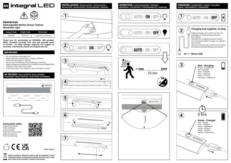
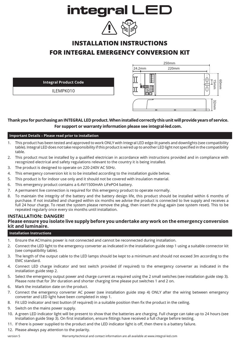
Integral LED ILEMPK010 User manual

Integral LED

Integral LED ILEMPK010 User manual

Integral LED ILSTRGBA162B User manual

Integral LED

Integral LED ILSTRGBA162B User manual

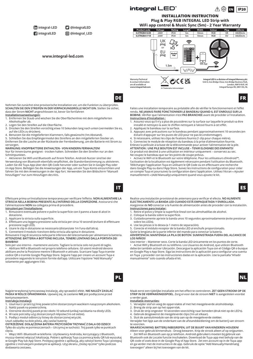
Integral LED ILSTRGBA163B User manual

Integral LED

Integral LED ILSTRGBA163B User manual

Integral LED ILGDA001 User manual

Integral LED

Integral LED ILGDA001 User manual

Integral LED ILSTRGBA173E User manual

Integral LED

Integral LED ILSTRGBA173E User manual

Integral LED ILSTRGBA165B User manual

Integral LED

Integral LED ILSTRGBA165B User manual

Integral LED ILRC020 User manual

Integral LED

Integral LED ILRC020 User manual

Integral LED ILBTX001 User manual

Integral LED

Integral LED ILBTX001 User manual

Integral LED SensorLux ILWL001 User manual

Integral LED

Integral LED SensorLux ILWL001 User manual

Integral LED ILSTRGBA166B User manual

Integral LED

Integral LED ILSTRGBA166B User manual

Integral LED SensorLux User manual

Integral LED

Integral LED SensorLux User manual

Integral LED ILBTC111 User manual

Integral LED

Integral LED ILBTC111 User manual

Integral LED SensorLux ILWL004 User manual

Integral LED

Integral LED SensorLux ILWL004 User manual

Integral LED ILDEA030 User manual

Integral LED

Integral LED ILDEA030 User manual

Popular Lighting Equipment manuals by other brands

Chauvet Intimidator wave irc user manual

Chauvet

Chauvet Intimidator wave irc user manual

Blizzard StormChaser user guide

Blizzard

Blizzard StormChaser user guide

Future light DJ-SCAN 200 user manual

Future light

Future light DJ-SCAN 200 user manual

Elation PROMETEUS MAXIMUS user manual

Elation

Elation PROMETEUS MAXIMUS user manual

Garden Lights 2519064 manual

Garden Lights

Garden Lights 2519064 manual

Nikkei RLIGHTX10 quick start guide

Nikkei

Nikkei RLIGHTX10 quick start guide

Spitzer LIGHTING STR-22-25W-CCT installation manual

Spitzer LIGHTING

Spitzer LIGHTING STR-22-25W-CCT installation manual

Safavieh TBL4050A quick start guide

Safavieh

Safavieh TBL4050A quick start guide

DS Produkte 3255-4 instructions

DS Produkte

DS Produkte 3255-4 instructions

JB Systems BABY FALCON Operation manual

JB Systems

JB Systems BABY FALCON Operation manual

ADJ ALLEGRO Z6 User instructions

ADJ

ADJ ALLEGRO Z6 User instructions

Cooper Metalux CGTS NUV installation instructions

Cooper

Cooper Metalux CGTS NUV installation instructions

Lightolier Lytecel Linear LL4MF8LR154 specification

Lightolier

Lightolier Lytecel Linear LL4MF8LR154 specification

PLG TINY PLEX user manual

PLG

PLG TINY PLEX user manual

Airsafe E0L-OB-LED Operation manual

Airsafe

Airsafe E0L-OB-LED Operation manual

XanLite PRSCAM250 manual

XanLite

XanLite PRSCAM250 manual

EuroLite AKKU Bar-4 HCL user manual

EuroLite

EuroLite AKKU Bar-4 HCL user manual

thomann Stairville DM 44 user manual

thomann

thomann Stairville DM 44 user manual

manuals.online logo
manuals.online logoBrands
  • About & Mission
  • Contact us
  • Privacy Policy
  • Terms and Conditions

Copyright 2025 Manuals.Online. All Rights Reserved.