95663 3 03/22
Translation of the Original Operation Manual
Übersetzung der Originalbetriebsanleitung
22
5 Shredder Operation
5.1 Operating the machine
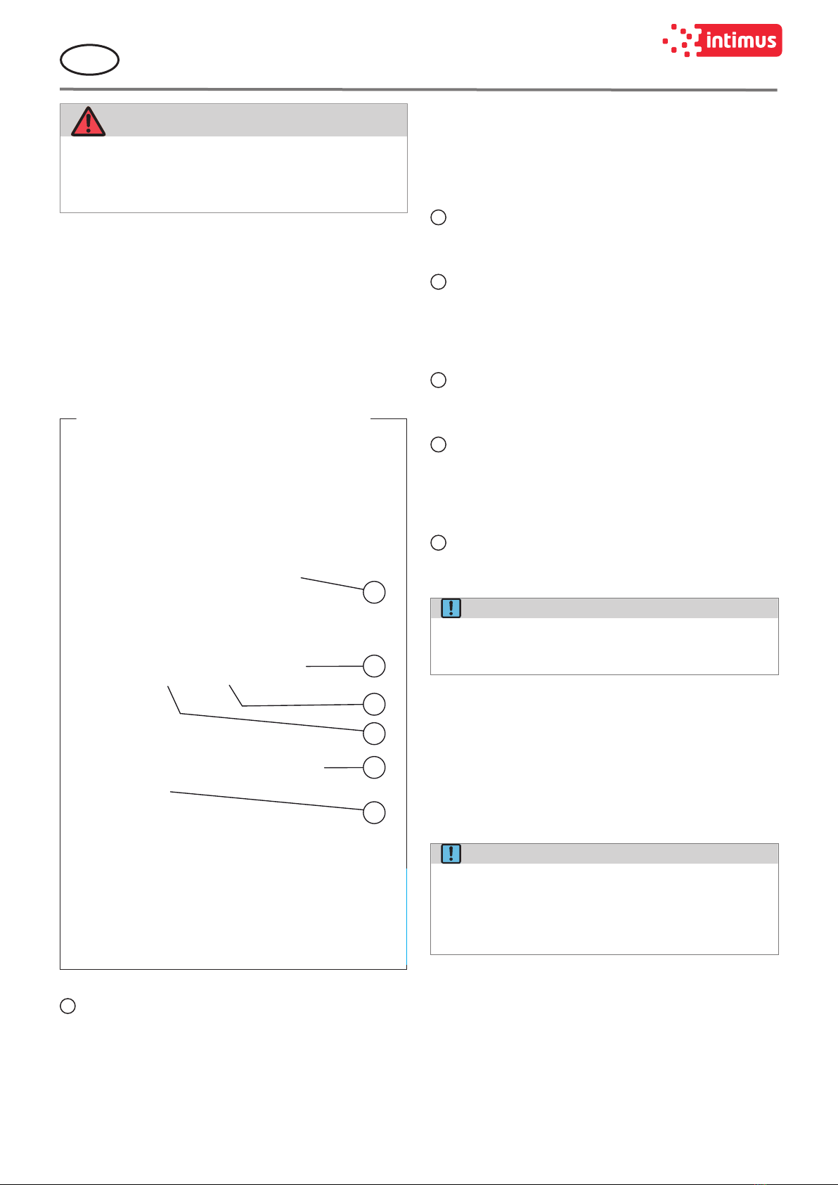
To switch on, proceed as follows:
1. Set the main switch (g.7/2) to position“1”.
2. Insert the enclosed key into the key selector switch
(g.7/1) and turn it to the right.
¾The display prompts you to close the safety circuit.
3. Press the “Reset” button.
¾The machine is now ready for operation.
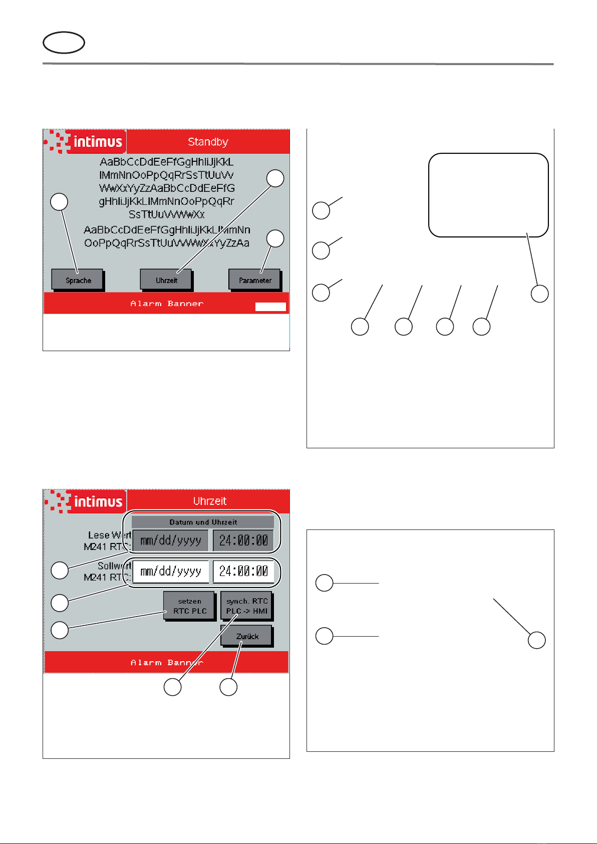
NOTE!
If, when the shredder is started, the baling ram
(g.14/1) of the baler is not in its basic position
(rearmost position), a compression stroke with fol-
lowing return stroke is carried out automatically
before the cutter and conveyor belt start.
Attention: The system only functions if:
• The emergency stop bar (g.6/1) is released (pull red
bar at table forward)
• The key switch (g. 7/1) has been unlocked (turn key
clockwise)
• The mains switch (g. 7/2) has been switched on (switch
position ”1”)
• The safety switch activator (g.4/1) has been inserted
into the safety switch at the baler
• The inlet ap (g.1/5), the discharge ap (g.1/1) and
the cover ap (g.1/3) are closed.
5.2 Loading the shredder
CAUTION!
Risk of injury from the cutting rollers, dama-
ge to the cutting mechanism!
)The operator may not stand higher than the
machine itself stands, when feeding paper
to the machine!
Standing on an raised platform (such as pallets
or boxes placed in front of the machine) reduces
the distance between operator and cutting sys-
tem to a level which does not meet the required
safety standard.
)Never feed the shredder with a quantity of
paper exceeding the maximum indicated in
the „Technical data“, p.28.
Should the machine become overloaded, follow
the instructions under „Automatic response in
case of „overloading““, p.22.
Feeding with smooth paper:
Feed material for the shredder can consist of stacks of
smooth paper (up to about 550 sheets, depending on the
type and size of paper); and also crumpled paper and card-
board. Place any material to be shredded on the moving
conveyor belt which feeds it to the cutting system.
It is advisable to place stacked paper diagonally on the belt.
In this way, the corner of the stack will be fed to the cutting
system rst, thus avoiding a sudden overload.
Feeding with complete binders:
Shredders equipped with a cutting system with 7.8x55 mm
or 10 x 70 mm cutting width, can also be fed with complete
binders (incl. metal parts). In this case the binder should be
opened and the contents spread out equally.
Important note: The removing of the metal parts before-
hand makes the recycling of the shredded material possible
and ensures a longer life of the cutting system.
5.3 Automatic response in case of
„overloading“
CAUTION!
Risk of injury!
Never pull paper from the cutting mechanism
by hand when the machine is performing an au-
tomatic feeding operation!
In case you accidentally overload the shredder, it will auto-
matically alleviate the problem as follows:
• The cutting system becomes jammed.
• The cutting system and the conveyor belt run briey in
reverse, thereby freeing the material to be shredded.
• The cutting system and the conveyor automatically
switch back to forward mode.
The machine repeats this process until the all the material
has been shredded satisfactorily.
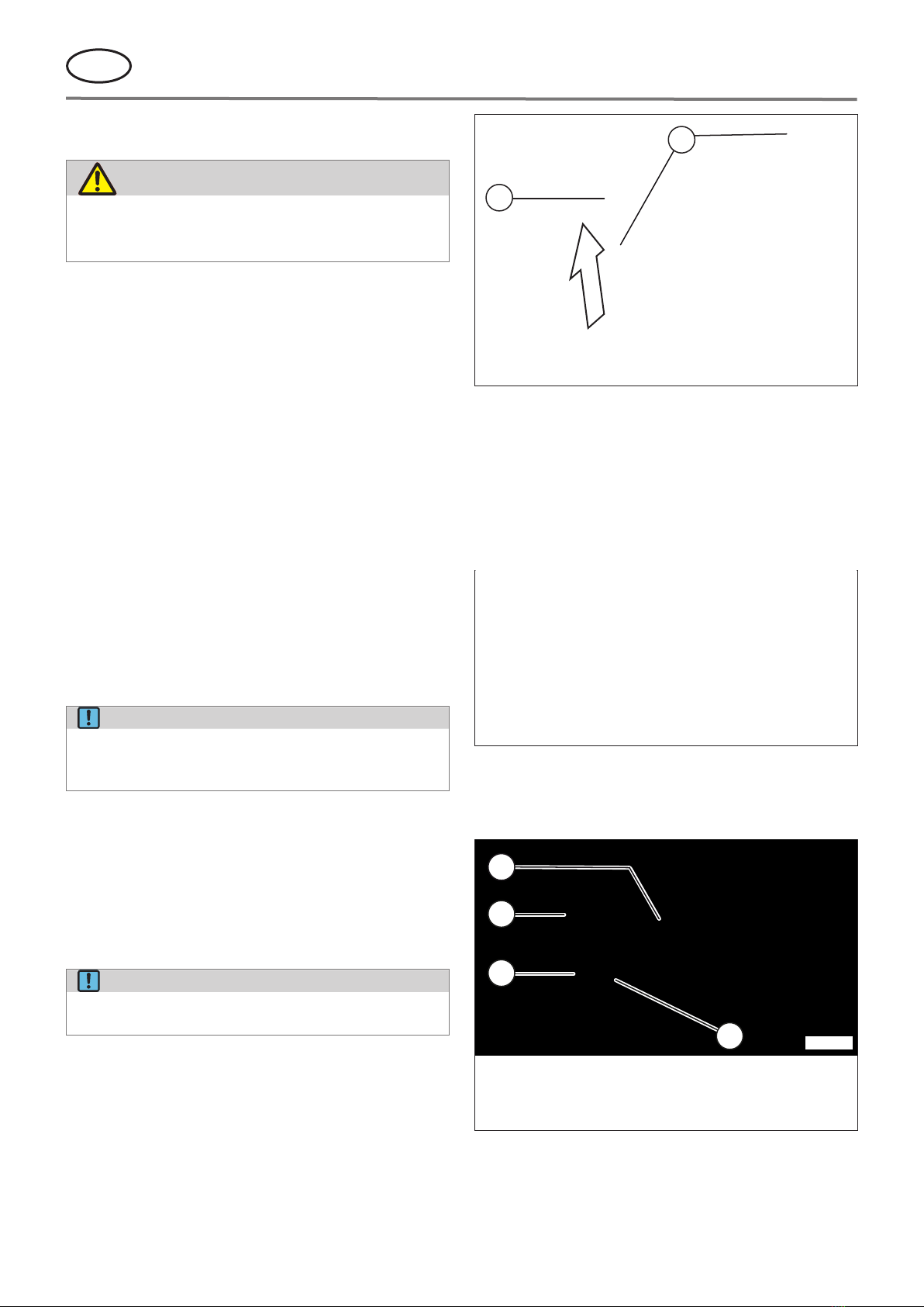
5.4 16.99 with baler: Jam outlet
If the space in the hopper (g.1/2) is completely lled with
cutting material due to a jam in the ller hole of the baler,
the machine switches o when the cover ap (g.1/3) is
raised.
A specic pop-up windows containing error messages ap-
pear on the display. These provide information about the
cause and remedies.
If this is the case, switch the machine o at the main switch
(g.7/2), lift up the cover ap and remove the material from
the machine by hand. Then you can switch the machine on
again and continue shredding.
NOTE!
The machine can only be started when the cover
ap (g.1/3) is closed.