1
SAFETY SUMMARY
The following recommendations are made for the
safeinstallationofthePersonalBackBottomMount-
ing Hardware:
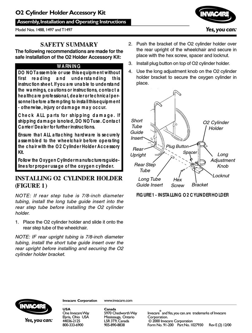
ITEM COMPONENT QTY.
1. Threaded Latch Pin 2
2. Nylon Locking Key 2
3. End Cap for Latch Pin 2
4. 3/16-inch Retaining Ring 2
5. Utility Spring 2
6. #10 Flat Washer 2
7. Ziplock Bag *1
8. Carton *1
* NOT SHOWN
This kit includes the following:
INSTALLING HARDWARE (FIGURE 1)
1. Move foam padding on inside of Personal Back shell
to access the mounting holes.
2. Insert the Threaded Latch Pin (Item1)from the back
of the Personal Back, threaded end first toward out-
side edge of Personal Back. Insert through first hole
ONLY.
3. Slide the #10 flat washer (Item 6) onto the threaded
end from the inside of the Personal Back.
4. Slide the Utility Spring (Item5)onto the Latch Pin and
slide threads of the Latch Pin through remaining hole.
5. Temporarily screw the Nylon Locking Key (Item
2) onto the Latch Pin to prevent Latch Pin from
falling out of the Personal Back. DO NOT USE
LOCTITE YET.
6. Locate the groove on the Latch Pin.
7. Push latch pin fully through Personal Back until
retaining groove is visible from inside Personal
Back.
8. This requires compressing the spring. Maintain
spring in compressed position to access groove.
9. Insert Retaining Ring (Item 4)into groove on Latch
Pin.
10. Release Latch Pin. It will be held in place by the
Retaining Ring.
Personal Back Bottom Mounting Hardware
Assembly, Installation and Operating Instructions
Kit No. MB 54
SAVE THESE INSTRUCTIONS
NOTE: Check all parts for shipping damage. In case of
damage, DO NOT use. Contact Carrier/Invacare for fur-
ther instruction.
GENERALWARNINGS
DO NOT install this equipment without first read-
ingandunderstandingthisinstructionsheet.Ifyou
are unable to understand the Warnings, Cautions
and Instructions, contact a healthcare profes-
sional, dealer or technical personnel if appli-
cable before attempting to install this equipment
- otherwise, injury or damage may occur.
INSTALLATIONWARNINGS
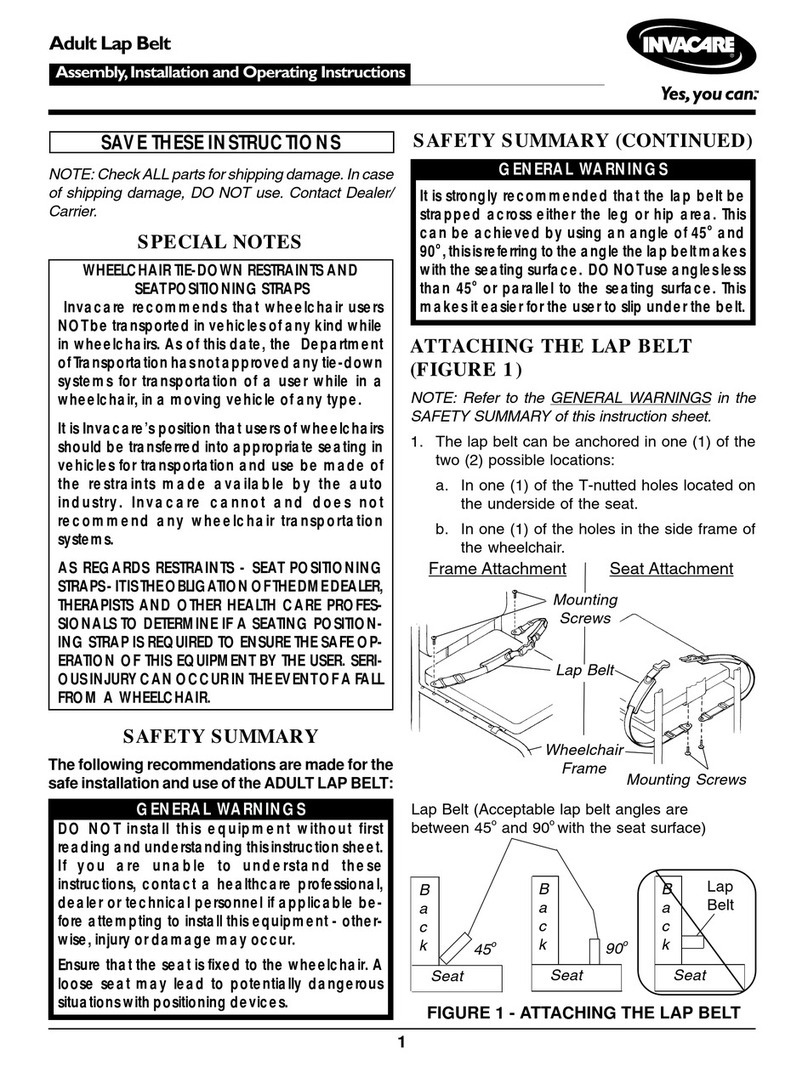
The position of the Personal Back in the different
mounting bracket slots is directly related to the
chair's stability. When the Personal Back is added
to a TILT and/or RECLINING chair, it may cause a
decrease in the chair's stability. It may be neces-
sary to reposition the FRONT CASTERS, REAR
WHEELS, BACK ANGLE, TILT-IN-SPACE, RECLINE PO-
SITIONand/orSEATDEPTHbeforeuse.UseEXTREME
caution when using a new seating position.
After ANY adjustments, repair or service and BE-
FOREuse,makesure thatall attachinghardware
is tightened securely.
INSTALLATIONCAUTION
When using LOCTITE 290, follow the manufac-
turers' recommendations.
USERWARNINGS
Skin condition should be checked frequently
after the installation of any new seat.
Yourtherapistandphysicianshouldbeconsulted
if you have any questions regarding individual
limitations and needs.
Working with your therapist, physician, and
rehabilitation technology supplier is the best
way to assure that a Personal Back choice
matches your individual needs.
As the needs of the individual become more
complex, the Personal Back evaluation be-
comes more important.
