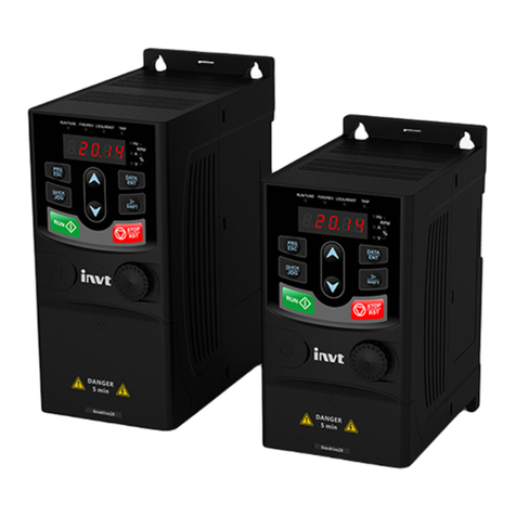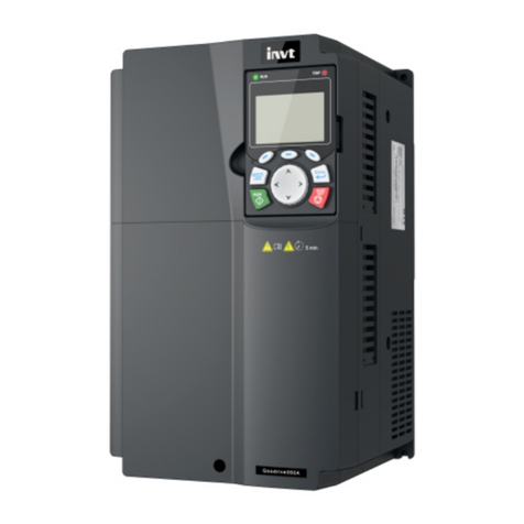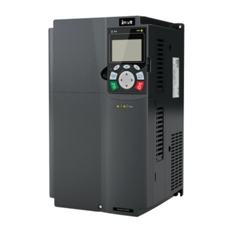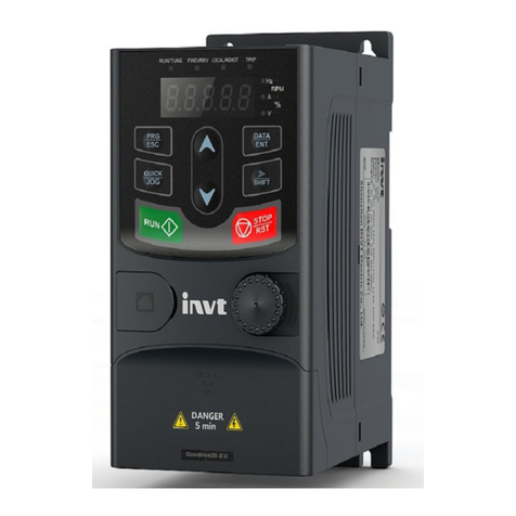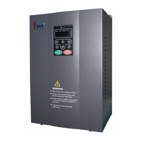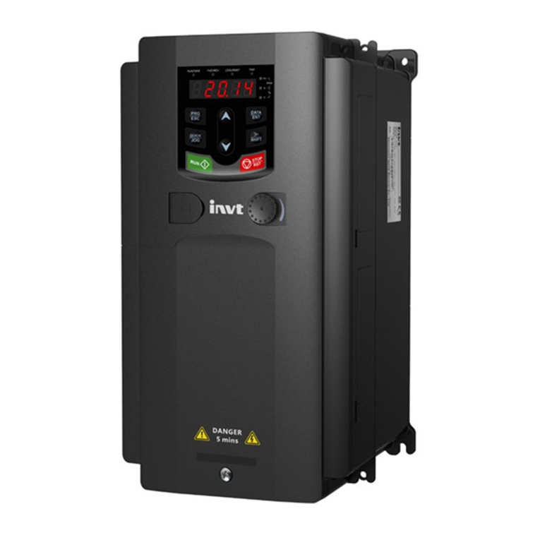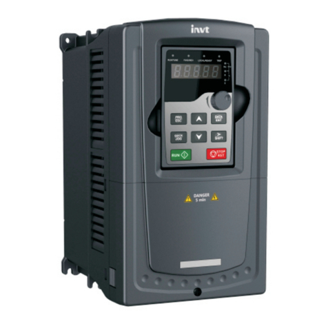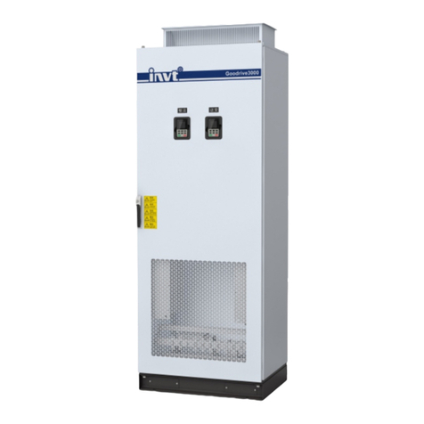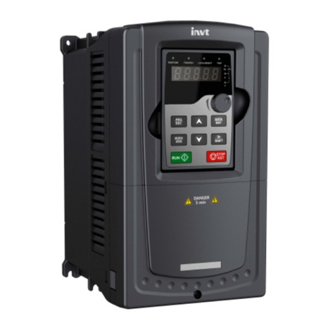
Goodrive300-01A series VFD for air compressor Contents
-iii-
P08 group Enhanced functions...........................................................................................61
P09 group PID control.........................................................................................................66
P11 group Protection parameters........................................................................................69
P13 group Synchronous motor control parameters.............................................................71
P14 group Serial communication ........................................................................................73
P17 group Status viewing ...................................................................................................74
P18 group Functions for air compressors ...........................................................................77
P19 group Air compressor status viewing ...........................................................................84
P20 group Function for water lubrication.............................................................................90
P21 group Power-frequency fan protection.........................................................................91
P25 group Fault policy ........................................................................................................93
5.2 Control logic of the air compressor.......................................................................................96
5.3 Fault policy function description ...........................................................................................98
6 Fault information and fault handling ........................................................................................102
6.1 VFD faults and solutions ....................................................................................................102
6.2 Fault contents and solutions of air compressor equipment ................................................106
Appendix A Product dimensions ................................................................................................. 111
A.1 Keypad diagram................................................................................................................. 111
A.2 External keypad installation dimensions............................................................................ 111
A.3 Wall installation dimensions of 380V–440V VFDs .............................................................112
A.4 Flange installation dimensions of 380V–440V VFDs .........................................................115
A.5 Wall installation dimensions of 520V–690V VFDs .............................................................117
A.6 Flange installation dimensions of 520V–690V VFDs .........................................................118
A.7 Floor installation dimensions of 520V–690V VFDs............................................................119
A.8 Product weight and package dimensions of 380V–440V VFDs.........................................120
A.9 Product weight and package dimensions of 520V–660V VFDs.........................................121
Appendix B External optional accessories.................................................................................122
B.1 Multi-function expansion card EC-IO304 ...........................................................................122
B.1.1 Brief introduction......................................................................................................122
B.1.2 Assembly instruction................................................................................................124
B.2 RS485 communication LCD keypad..................................................................................127
B.2.1 LCD keypad introduction..........................................................................................127
B.2.2 LCD keypad structure..............................................................................................130
B.2.3 RS485 communication cable...................................................................................130
B.2.4 Setting parameters on the LCD keypad...................................................................131
B.2.5 Fault records............................................................................................................151
B.2.6 VFD information.......................................................................................................153
B.2.7 System configuration ...............................................................................................154
B.3 HMI touch screen...............................................................................................................161
B.3.1 Specifications...........................................................................................................161
