The charger is equipped with a function of measuring the cells’ internal resistance,
which is only applied when conducting balanced charging. The cell voltage should
be measured and calculated within 2 to 3 minutes after the charging task has been
initiated. The battery internal resistance can slightly vary under different electric
quantities while the measured resistance value is usually relatively low as the
electric quantity is large.
The charging current should be adjusted instantly as the charger measures the
internal resistance of the battery; therefore, it is normal phenomenon for acute
change of current to occur during charging.
Internal resistance measurement function
10
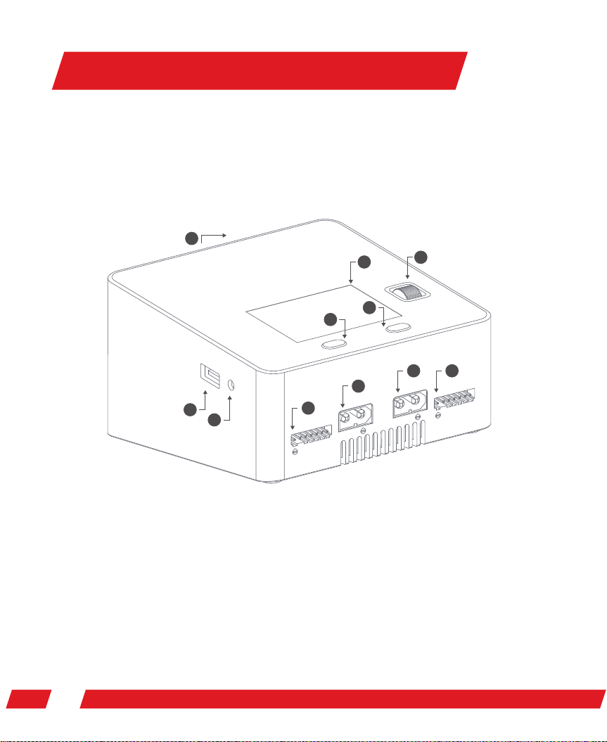
The working mode of the charger is series charging; you must therefore connect it to the
output line of the battery while charging. For a lithium battery, it is highly suggested that
the balanced interface should be connected to carry out balanced charging to accurately
monitor the voltage of each cell and balance the ones with bad consistency.
If battery voltage is lower than storage voltage, charger will charge battery to
storage voltage. If battery voltage is higher than storage voltage, charger will
discharge battery to storage voltage. In order to save storage time, battery might not
be accurately balanced, this is normal and there will not do any harm to battery.
Storage functions
Activation and restoration functions of excessive discharged battery
When the charging task begins, one tenth of the setting current should be applied
to activate and restore the battery if the cell voltage is tested to be lower than the
pre-charge voltage; on the other hand, it should be adjusted to a rated voltage for
charging when the cell voltage is higher than the pre-charge voltage. This design
can protect excessively discharged batteries, as well as conduct activation and
restoration.
Activation and restoration functions of excessive discharged battery
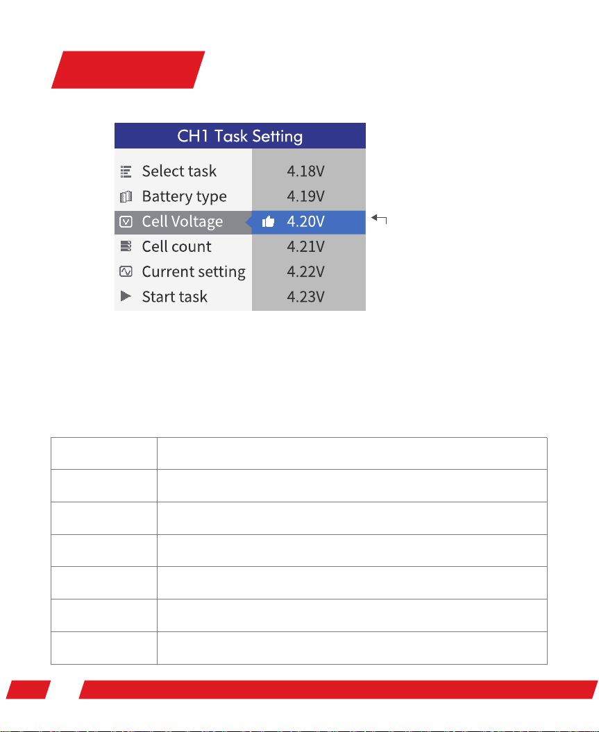
Task Setting