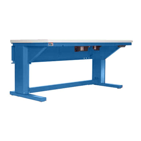
ITEM Work bench E User manual

User guide
Work bench E, 4 E and 4 E FIFO

2
Contents
1.5 CE declaration 5
9. Maintenance and servicing work 14
10. Disassembly and replacement of parts 14
11. Disposal 14
12. Annex 15
12.1 Installation declaration for the table columns 15
12.2 Specification plates 16
1. General safety information 3
1.1 Correct use 4
1.2 Improper use 4
1.3 Personnel qualifications 4
1.4 Warning symbols 4
2. Product description 6
3. Operating data 8
4. Setting up the height-adjustable work bench 8
4.1 Environmental considerations 8
4.2 Levelling the work bench 8
5. Electrical connections for height-adjustable tables 9
6. Start-up 10
6.1 Initialising the table columns when starting up the system for the first time (RESET) 10
7. Functions
7.1 On-time limiter
11
11
7.2 Safety range 11
7.3 Overload detection 11
7.4 Soft start/soft stop 11
7.5 Movement lock 11
7.6 Memory function 11
8. Error messages on the manual controls 13
6.2 Operation 10
7.7 Setting the upper and lower travel limits 12
7.6.1 Moving the table columns to stored heights 11
7.8 Switching between cm / inch 12

3
The details and information in the user guide are provided solely for the
purpose of describing the product and its assembly. The information does not
discharge the user from the obligation to carry out his own assessments and
checks. It is important to bear in mind that our products are subject to a natural
process of wear and ageing.
These notes contain important information that will enable you to use the
product safely and appropriately. When sold, rented out or otherwise passed on
to another party, this product must be handed over with the user guide.
When installing, operating and maintaining the electrical, height-adjustable
work bench, it is important to ensure that all moving elements are secured
so that they cannot be switched on and moved unintentionally. Rotating and
moving parts can cause serious injury! You must therefore read and follow the
safety instructions set out below.
All work on and with the electrical, height-adjustable work bench must be
performed with “safety first” in mind.
Switch off the power to the table columns before carrying out any work on the
electrical, height-adjustable work bench.
Ensure the table columns cannot be switched on unintentionally, e.g. by affixing
warning notices at the activation point or by removing the fuse from the power
supply.
Do not place your hand within the operating range of the electrical, height-
adjustable work bench’s moving parts when it is still switched on.
Fit guards and covers to the moving parts of the electrical, height-adjustable
work bench to ensure they are not touched unintentionally.
Observe the regulations pertaining to accident prevention and environmental
protection that apply in the country and place of work where the product is
being used.
Use only item products that are in perfect working order.
Failure to use original spare parts will invalidate the product warranty!
Check the product for obvious defects.
Use the product only within the performance range described in the technical
data.
Ensure that all the safety equipment associated with the product is present,
properly installed and in full working order.
Do not alter the position of safety equipment, circumvent it or render it ineffec-
tive.
The electrical, height-adjustable work bench described here corresponds to the
state of the art and takes into account the general principles of safety applica-
ble at the time this user guide was published. Nevertheless, failure to observe
the safety instructions and warning notices in this user guide may result in
personal injury and damage to property.
We will assume no liability for any resulting damage or injury. We reserve the
right to make technical changes that represent technical advances. Keep these
installation notes in a place where they can be easily accessed by all users.
Observe the directions contained in the main user guide for a system.
The general safety information applies to the entire lifecycle of the electrical,
height-adjustable work bench.
1. During transportation
Observe the handling instructions on the packaging. Until it is installed, the
product must be stored in its original packaging, protected from moisture and
damage. Ensure that moving parts are secured when in transit and cannot
cause any damage. Suspended loads can fall during transport if load-bearing
equipment is not fit for purpose or is incorrectly secured, thus leading to serious
injuries (including fatal injuries).
Keep clear of suspended loads.
Use lifting tackle with sufficient load-bearing capacity (see delivery paper-
work for product weight).
Carefully secure lifting tackle.
Attach lifting tackle to the product only at sufficiently stable points.
Always set down the height-adjustable work bench on a level surface.
Observe environmental regulations.
2. During installation
Always deactivate the power to the relevant system part and ensure it is not live
before installing the product and/or plugging it in or unplugging it. Ensure the
system cannot be switched back on. Lay cables and lines in such a way that
they cannot be damaged and do not represent a trip hazard. Avoid areas that
pose slip, trip and fall hazards.
3. During start-up
Allow the product to acclimatise for a few hours before starting it up.
Ensure that the partly completed machine is securely and safely integrated into
the completed machine. Only start up a product that has been installed in full.
4. During operation
Ensure that only persons who have been authorised by the operator have ac-
cess to the immediate operating area of the height-adjustable work bench. This
also applies when the system is not in operation. It must not be possible to actu-
ate moving parts unintentionally. During emergencies, malfunctions or other
irregularities, deactivate the height-adjustable work bench and ensure it cannot
be switched back on. Ensure that nobody can step below suspended loads and
prevent access below the working surface of the height-adjustable work bench.
The height-adjustable work bench is not suitable for lifting people.
5. During cleaning
Close all openings with suitable protective equipment to ensure that cleaning
agents cannot penetrate the system. Do not use aggressive cleaning sub-
stances. Do not use a high-pressure cleaner when cleaning the system.
6. During maintenance and servicing work
Carry out the prescribed maintenance work at the intervals stipulated in the
user guide. Ensure that no cables, connections or components are detached or
removed while the system is live. Ensure that the height-adjustable work bench
cannot be switched back on.
7. During disposal
Dispose of the product in accordance with the national and international regula-
tions that apply in your country.
1. General safety information
4
The electrical, height-adjustable work bench is a partly completed machine as
defined in the Machinery Directive (2006/42/EC). The electrical, height-adjus-
table work bench must only be used in accordance with the technical data and
safety requirements set out in this document. The electrical, height-adjustable
work bench is a technical item of work equipment and is not intended for
private use.
If major alterations are made to the electrical, height-adjustable work bench,
compliance with the Machinery Directive will need to be renewed and the
documentation supplemented accordingly.
The electrical, height-adjustable work bench is a moving device for the separate
raising and lowering of the working surface and accessories.
Internal company requirements and the regulations that apply in the country
where the product is being used must be observed. You must not make any
design modifications to the electrical, height-adjustable work bench yourself.
We will assume no liability for any resulting damage or injury.
You may only install, operate and maintain the electrical, height-adjustable work
bench if:
The electrical, height-adjustable work bench is used only in a fixed, station-
ary location,
You integrate the electrical, height-adjustable work bench into its surround-
ings in a proper and safe manner. The operator is responsible for ensuring
proper and safe installation,
You have carefully read and understood the installation guide,
You are appropriately qualified,
You are mentally and physically capable of doing so,
You are authorised to do so by your company,
You are using only original equipment from the manufacturer.
Unsafe or inappropriate use of the electrical, height-adjustable work bench runs
a risk of serious injury through crushing and cuts.
Improper use is defined as any use of the product for purposes other than those
authorised in the user guide and under the definition of correct use. We will
assume no liability for any resulting damage or injury.
Assembly, commissioning, operation, disassembly and maintenance work
(including servicing and care) require an adequate knowledge of electrical
and mechanical engineering and an understanding of the relevant technical
terminology. To ensure operational safety, these activities must therefore be
carried out only by a qualified person or by personnel under the instruction and
guidance of a qualified person
A qualified person is an individual who – by virtue of his or her specialist train-
ing, know-how, experience and knowledge of pertinent regulations – is able to
assess the work that is assigned to him or her, recognise potential hazards and
put in place appropriate safety measures. A qualified person must comply with
the applicable specialist regulations.
Attention, Warning
Information
1.1 Correct use
1.2 Improper use
1.4 Warning symbols
1.3 Personnel qualifications

5
1.5 CE declaration

6
a
b
s
790
80
160
680 - 1100
680-1100
160
600 / 750
1200 / 1500 / 1800
1100680 - 1100
1200 / 1500 / 1800
1280
600 / 750
1830
Table E
Table 4 E
Table 4 E FIFO
The item work bench 4 E FIFO – a logical and efficient combination of work bench and FIFO rack. Strong and steady with a customisable configuration.
Work bench 4 E FIFO
2. Product description
Work bench E
Two table columns at the rear of the table, table top positioned on stable steel supports. An electrical, height-adjustable work bench that is easy to operate and
incorporates a control system with a memory function. This means that the working height can be adjusted to suit whoever is using the table at any one time.
Work bench 4 E
An electrical, height-adjustable work bench incorporating a control system with a memory function. For applications where exceptional stability and load-carrying
capacity are essential. The table top is supported by four columns.
Four different working surfaces are available for all tables:
Plastic-coated, high pressure laminate (HPL), HPL/ESD-safe and beech multi-ply.
You can combine work benches with a number of useful accessories from our broad range of add-ons.
These include solutions for power and data supply, work bench lighting, pivot arms, a diverse range of ESD accessories and mounting systems for PCs and tools.
The electrical, height-adjustable basic frames of tables E and 4 E can be extended by adding an upright or an upright with overhang.
It is possible to extend the work bench 4 E FIFO by adding an overhang.
Electrical, height-adjustable basic frames:

7
20
≤ 640
≤ 1300
s
a
480
1100
a
a-120
Work Bench E Table Top material Optional attachments
Dimensions
a x b mm
plastic coated
s = 25 mm
high pressure
laminate
s = 30 mm
high pressure
laminate/ESD
s = 30 mm
beech multi-ply
s = 40 mm
Upright Overhang
(Upright required)
Cable Duct E
1200 x 600 • • • •
1200 x 750 • • • •
1500 x 600 • • • •
1500 x 750 • • • •
1800 x 600 • • • •
1800 x 750 • • • •
Work Bench 4 E Table Top material Optional attachments
Dimensions
a x b mm
plastic coated
s = 25 mm
high pressure
laminate
s = 30 mm
high pressure
laminate/ESD
s = 30 mm
beech multi-ply
s = 40 mm
Upright Overhang
(Upright required)
Cable Duct E
(Upright required)
1200 x 600 • • • • •
1200 x 750 • • • •
1500 x 600 • • • • •
1500 x 750 • • • •
1800 x 600 • • • • •
1800 x 750 • • • •
• • • •
• • • •
• • • •
• • • •
• • • •
• • • •
Work bench 4 E FIFO Table top material Optional attachments
Dimensions
a x b mm
Plastic coated
s = 25 mm
High pressure
laminate
s = 30 mm
High pressure
laminate/ESD
s = 30 mm
Beech multi-ply
s = 40 mm
Overhang Cable Duct E
(Upright required)
1200 x 600
1200 x 750
1500 x 600
1500 x 750
1800 x 600
1800 x 750
The Upright The Overhang
•
Required
○Optional

8
d
M
Table 4 ETable E
4. Setting up the height-adjustable work bench
This height-adjustable work bench is intended as a permanent fixture in an area
that is protected from the weather.
The area should be free from mould and fungus and show no traces of
rodents or other pests.
Do not install or use in close proximity to industrial plants that produce
chemical emissions.
Do not install or use near sources of sand or dust.
Do not install or use in an area that is regularly exposed to high-energy
surges such as those caused by presses or heavy machinery, for example.
Resistant to many of the substances usually encountered in the production
area, such as water, mineral oil, grease and detergents. In case of doubt
regarding resistance to certain chemicals such as test oil, alloyed oils,
aggressive cleaning substances, solvents or brake fluid, we advise that you
consult your specialist representative.
Avoid long periods of contact with highly acidic or alkaline substances.
Consult the manufacturer if using in very salty air.
4.1 Environmental considerations
Work bench designs must take into account
the maximum permissible torque load for the
table columns of Mmax. = 140 Nm.
4.2 Levelling the work bench
Table 4 E FIFO
To set up the assembled, height-adjustable work bench, you will need the
following tool:
Spirit level
Faults may occur as a result of incorrect set-up or start-up. The height-adjust-
able work bench may be damaged and the service life may be shortened.
When setting up the work bench on uneven ground, use the spirit level to
ensure it is square and axially parallel.
Do not load the table columns to the point that they start to deflect.
Initialise (reset) the table columns before they are mechanically fixed
together.
The height-adjustable work benches E, 4 E and 4 E FIFO are already
initialised and ready for use when supplied.
Level the workbench by twisting the adjustable feet underneath the table
columns in or out by hand and check using a spirit level.
3. Operating data
Single column 1000 N
Table E 2 columns 2000 N distributed
Table 4 E / 4 E FIFO 4 columns 4000 N distributed
Perm. bending moment in travel mode 140 Nm
Speed 25 mm/s
Temperature range -5°C to +40°C
Noise emissions < 70 dB (A)
Travel range, Table E 680 mm – 1060 mm
Travel range, Table 4E 680 mm – 1100 mm
Threaded bores mounting plates 4 x M8x8
2 x M10x8
Storage temperature -25 °C to +70 °C
Relative humidity 5 % to 85 %
Air pressure > 84 kPa, equiv. to altitude of < 1400 m above sea level
In altitudes > 1400 m, the load values are reduced by 15%.
Maximum loading of overhang 200 N
Selection and installation of the appropriate components ensures suitability
for use in areas where electrostatic charges pose significant hazards. We
recommend that you consult your item representative.

9
6 pole DIN socket
Manual controls
8 pole DIN socket
Table column 2 8 pole DIN socket
Table column 2
8 pole DIN socket
Table column 1 8 pole DIN socket
Table column 1
6 pole DIN socket
Manual controls
Table E: ST2
8 pole DIN socket
Table column 4
8 pole DIN socket
Table column 3
Table 4 E: ST4
Control units
The synchronous control systems are used to control height-adjustable table
systems for 2 or 4 table columns
2 table columns EU; 230 VAC
USA/CDN; 120-277 VAC
4 table columns EU; 230 VAC
USA/CDN; 120-277 VAC
The on-time is 10%, which means that the table columns can
be run for 2 minutes in continuous operation and will then
switch off for 18 minutes.
Check the seating of all plug connections.
Use a power cord to connect to the mains.
The control system and manual controls must be positioned and secured as
appropriate to local conditions. If necessary, alter their position.
The installation site should be dry, free of dust and away from direct sunlight.
The environmental temperature for operating the control system must not fall
below 5 °C or above 35 °C.
Consequently, you should not install the control system:
- above or in front of heat sources (e.g. radiators),
- in locations that are exposed to direct sunlight,
- in small, unventilated, damp rooms,
- on or near highly flammable materials or
- near high-frequency devices
(e.g. transmitters, radiation-emitting devices or similar equipment).
Ensure that connecting cables and electrical lines are not bent, pulled or
subjected to mechanical loads. In particular, cables must not be clamped in
the foot area of the table columns (safety area of approx. 10 mm around the
table column feet).
It is advisable to install surge protection to protect against the types of
electrical surges that can occur during thunderstorms. Consult an electrical
engineer.
Never open the control system’s housing or the power pack! Unauthorised
opening of the housing and inappropriate repairs can cause hazards for us-
ers and shall invalidate the warranty. Only the manufacturer’s personnel are
authorised to open or repair the electrical systems.
Do not allow any liquids to penetrate inside the control system or the power
pack as this could result in an electric shock or short circuit.
Use only a dry or slightly damp cloth to clean the control system and the
manual controls.
Stop using the device immediately if it begins to emit smoke or odour, makes
unusual noises or shows visible signs of damage. Disconnect the system
from the mains by removing the plug.
The control system may only be used with item table columns.
5. Electrical connections for height-adjustable tables
Observe the following points when installing and operating the control system:

10
.
RESET following a power failure
If there is a power cut while the table columns are moving, the system will need
to be RESET before the table can be used again as normal.
DOWN
RESET (initialise) the system:
Hold down the “DOWN” and “UP” buttons together. After a brief pause, the
travel modules travel downwards to the mechanical stop and switch off. Now
release the buttons. The RESET is confirmed by an audible signal that sounds
three times. The system is now ready.
UP
DisplayMM1 M2 M3
6.2 Operation
Manually adjusting the table column height
Use the “DOWN” button to move down and the “UP” button to move up.
The display shows the absolute working height of the construction
in cm only when the minimum height of the adjustable construction
has previously been set to 665 mm.
The table columns travel up and down at normal speed for as long as
the relevant button is held down. The table columns are automatically
stopped before they reach the mechanical stop position.
If the table columns are travelling downwards, the travel module stops automatically a few centimetres before they reach the stop position. Pressing the “DOWN”
button again causes the table columns to travel downwards at a reduced speed until they reach the stop position (safety feature to prevent e.g. body parts being
caught).
If the table columns are already within the safety range and are to be lowered further, but were previously being moved upwards, press the “DOWN” button twice.
6.1 Initialising the table columns when starting up the system for the first time (RESET)
When a table that has not previously been initialised is started up for
the first time, or when a corresponding error message is displayed, the
system needs to be RESET before the table can be used as normal.
The height-adjustable work benches E, 4 E and 4 E FIFO are already
initialised and ready for use when supplied.
During the initialisation process (RESET), the control system synchronises the
travel heights of the connected table columns.
Uncontrolled movement in the table columns during initialisation (RESET) can
damage the columns and shorten the service life.
During initialisation (RESET), do not restrict the movement of the table
columns by means of any mechanical connection.
The connected table columns need to be initialised (RESET):
When a faulty table column has been replaced,
When an error message has been issued (A 64: RESET – compulsory), e.g.
after a power cut that has occurred while the table columns were moving.
The reset journey (initialise) is carried out at reduced speed.
6. Start-up
The basic function of the control system is to raise or lower the table. Both
of these functions can be performed via the table’s manual controls (before
changing the manual controls, remove the power plug; it may be necessary to
reset the system).
When starting up the table:
When running the drive, please ensure that no objects (e.g. furniture)
or body parts become trapped.
To prevent crushing and cuts, nearby objects should be kept at a
minimum distance of 25 mm from the table columns.
Load values must not be exceeded.
Safety instructions must be followed.
Inappropriate use of the system can pose hazards to people and
equipment.
The product warranty is valid only when the product is used in accor-
dance with the stipulations in this user guide.
Loading under tension of the table columns is forbidden.
The height-adjustable work bench can be damaged if it comes into
contact with obstacles, and the service life may be shortened.
Keep the travel area beneath the table top and the safety area around
the table column feet clear.
The work bench 4 E FIFO is accessible from both sides. Due to its size,
the work bench occupies a large, confusing moving space. The acces-
sibility on both sides of the work bench 4 E FIFO must be guaranteed
safe from both sides, according to the tasks.
Hazard must be avoided for the personnel on both sides, during the
move of the work bench. Unforeseeable risks with new installations at
the work bench or the FIFO Storage space need a new assessment of
risk and a new declaration of conformity, if necessary.
Table tops or equipment must be rigidly connected to the drive system.
For this reason, it is forbidden to connect the adjustable feet or the base
plate of the table columns rigidly to the floor, this leads to a certain ad-
ditional guidance and so the table columns will be damaged.

11
7. Functions
7.1 On-time limiter
The electronic system monitors how long the table columns have been active. If the maximum permissible time is
exceeded, the electronics will not permit any further movement in the table columns. This protects the power pack, control
system and drives against overload.
7.2 Safety range
A certain section of the table columns (a few cm before the lower stop position) is referred to as the safety range. When
the table columns reach this point, they stop. When the “DOWN” button is pressed again, they continue moving down,
but at a reduced speed. If the table columns are to be lowered when they are already within the safety range, and were
previously being moved upwards, the “DOWN” button will need to be pressed twice.
7.3 Overload detection
The control system detects an excessive load (weight) on the construction and switches off. The table columns are oper-
ated at reduced speed briefly after they are started/before they are stopped.
7.4 Soft start/soft stop
The drives are operated at reduced speed briefly after they are started/before they are stopped.
7.5 Movement lock
When the movement lock is engaged, the table columns cannot be moved, thereby preventing uncontrolled move-
ment of the construction.
Press the “M” button for 10 seconds to engage or disengage the movement lock.
7.6 Memory function
Additional memory function for the storage of height settings and for moving the table to these heights.
1. Manually adjusting the table height.
2. Storing a height setting (memory)
The control system can store three standard positions.Press the “M” button three times to access memory mode.
Within 5 seconds, press one of the three buttons M1, M2 and M3 to store the height position currently set.
The control system issues an audible signal to confirm that the setting has been stored in the memory.
7.6.1 Moving the table columns to stored heights
Hold down one of the three buttons M1, M2 and M3 until the corresponding position is reached.

12
.
7.7 Setting the upper and lower travel limits
7.8 Switching between cm / inch
The travel distance can be electronically limited to prevent collision with any potential obstacles in the travel range. For reference purposes, the lower
mechanical limit switch must stay within range.
Press the “M” button eight times to enter setting mode. An audible signal indicates the setting mode is active.
Press the UP or DOWN button to move the table columns to the desired upper or lower travel limit.
When the columns are in the correct position, press the “M” button three times and then press the UP or DOWN button, depending on which limit is
selected.
An audible signal issued by the controller confirms that the correct setting has been adopted.
To reset the travel limit, re-enter setting mode by pressing the “M” button eight times. When the audible signal indicates that setting mode is active, move
the table columns through the entire adjustment range, right up to the absolute end positions, and re-save the positions.
To save a new position, press the “M” button three times and then press the UP or DOWN button. An audible signal issued by the controller confirms that
the selected setting has been adopted by the controller. Programmed travel limits cannot be overridden with the memory or arrow buttons.
If no buttons are pressed for 10 seconds when in setting mode, the process is automatically terminated. An audible signal is then sounded.
Caution: Collisions with obstacles in the travel range can cause serious damage and injuries.
It is the operator’s responsibility to ensure the travel range is clear of any obstacles.
Press the “M” and “UP” buttons together to change the display between centimetres and inches.
UP
M

13
Cause
.
Solution
Travel monitor
1. The table could be jammed or overloaded.
2. A motor is incorrectly connected to the control
system.
1. Remove the load and move the table a short distance
in the opposite direction.
2. Check the plug connection and RESET the system
(see 6.1).
If the error persists, contact your service partner.
Faulty motor signal Check the plug connections of the columns. It may be
necessary to replace the control system or columns.
Replace the parts or contact your service partner.
Motor not recognised
Check the plug connections.
If the error persists, the column or control system is
defective.
Replace the parts or contact your service partner.
On-time limiter/overheating protection The electronic system monitors how long the drives
have been running. If the maximum permissible time is
exceeded, the electronics will not permit the drives to be
run any longer.
This protects the power pack, control system and drives
against overload.
Overheating:
The control system has exceeded the permitted
temperature.
You must wait until the transformer has cooled down. How
long this will take depends on the ambient temperature.
Overcurrent in drive:
One or more drives are overloaded.
Check the permissible load for the table in the installation
guide.
Remove the cause of the overload. Check that the table
has been properly assembled and is free from strain.
If the error persists, contact your service partner.
Short circuit –
manual controls connection
Check the connections. The control system or the manual
controls may be faulty.
Replace the faulty part.
If the error persists, contact your service partner.
Short circuit –
motor connection
Check the connections. The control system or the guiding
column may be faulty.
Replace the parts.
If the error persists, contact your service partner.
Control system faulty Replace the control system or contact your service
partner.
Reset – compulsory Please RESET the system (see 6.1).
Movement lock engaged Press the “M” button for 10 seconds.
A CA
A C9
A D7
A 6F
A 70
A 71
A 72
A 73
E DE
E E9
If the manual controls display a fault code that is not listed in the table, contact the manufacturer.
A65
A64
E D4
E D7
E 6A
8. Error messages on the manual controls

14
9. Maintenance and servicing work
10. Disassembly and replacement of parts
11. Disposal
There are no maintenance requirements associated with the height-adjustable work bench.
See Section 9 for warning/error messages and solutions.
Touching live parts can lead to an electric shock, causing serious injuries or death.
Before carrying out maintenance work, switch off the power supply.
Put in place suitable measures to prevent the power supply from being switched back on unintentionally.
Use only original spare parts.
The materials used are environmentally friendly.
They can be recycled or re-used (if necessary after refurbishment and the replacement of parts).
The use of appropriate materials and easy dismantling ensure the product can be recycled.
Improper disposal of this height-adjustable work bench can pollute the environment.
Please dispose of your height-adjustable work bench in full accordance with the laws of your
country.

15
12. Annex
12.1 Declaration of incorporation for the table columns

Workbench type
4 E
AB. No.
Input
230V 50Hz 2,7A
Duty cycle
10%, 2min/18min
Maximum load
4000N
Serial number, Control Unit
Serial number, Table Column 1
Serial number, Table Column 2
Serial number, Table Column 3
Serial number, Table Column 4
Manufactured by:
Date
www.item24.com
0.4.119.26 12/2013 Made in Germany
Workbench Type
E
AB. No.
Input
230V 50Hz 2A
Duty cycle
10%, 2min/18min
Maximum load
2000N
Serial number, Control Unit
Serial number, Table Column 1
Serial number, Table Column 2
Manufactured by
Date
www.item24.com
0.4.119.25 12/2013 Made in Germany
Workbench type
4 E FIFO
AB. No.
Input
230V 50Hz 2,7A
Duty cycle
10%, 2min/18min
Maximum load
4000N
Serial number, Control Unit
Serial number, Table Column 1
Serial number, Table Column 2
Serial number, Table Column 3
Serial number, Table Column 4
Manufactured by:
Date
www.item24.com
0.4.121.90 12/2013 Made in Germany
item Industrietechnik GmbH
Friedenstrasse 107-109
42699 Solingen
Germany
Phone +49 212 6580 0
Fax +49 212 6580 310
info@item24.com
www.item24.com
© item Industrietechnik GmbH Made in Germany
12.2 Specification plates
0.4.119.28 04/2018
You find the Notes on Use and Installation
online, in the download section for this
product.
This manual suits for next models
2
Table of contents
Other ITEM Tools Storage manuals