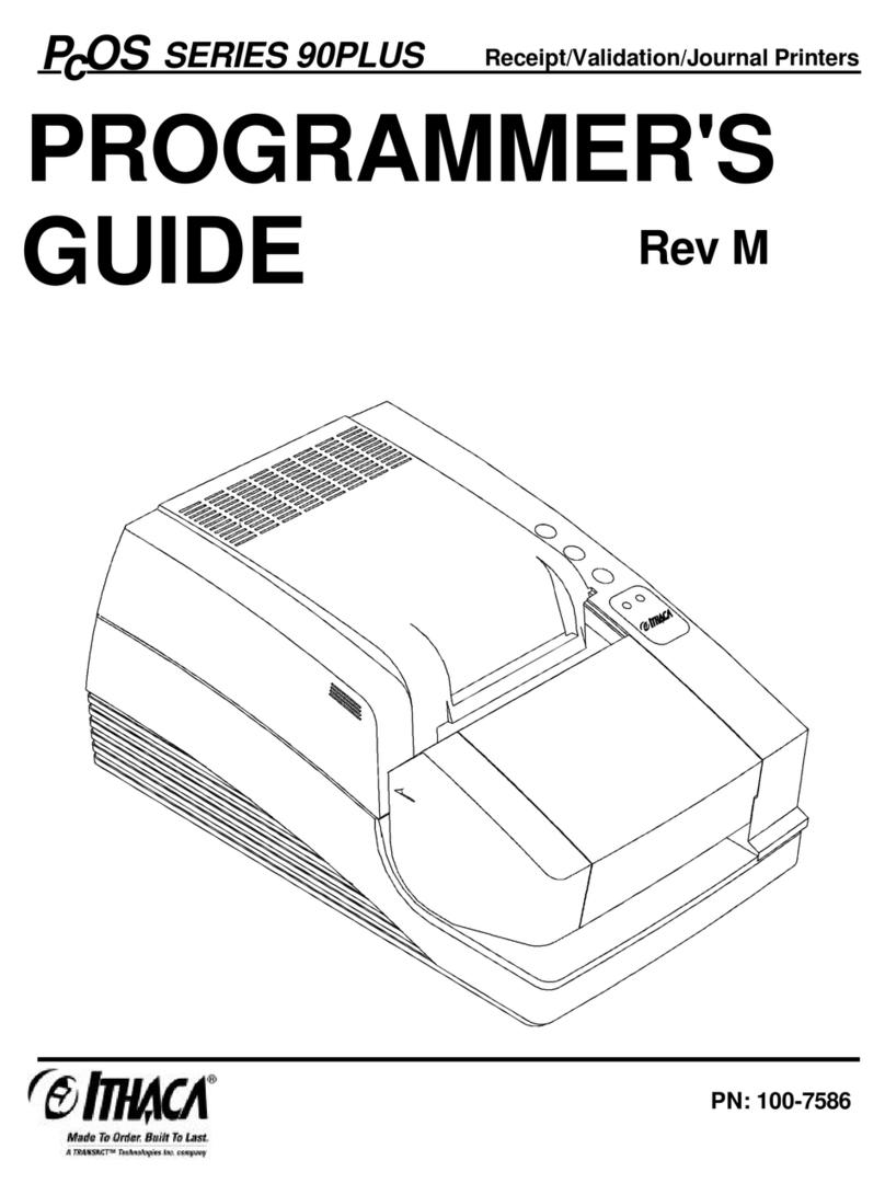
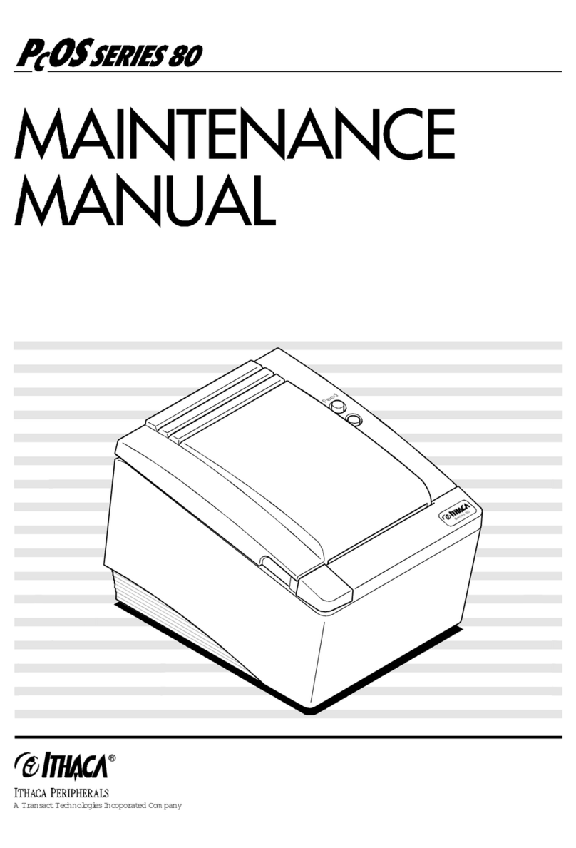
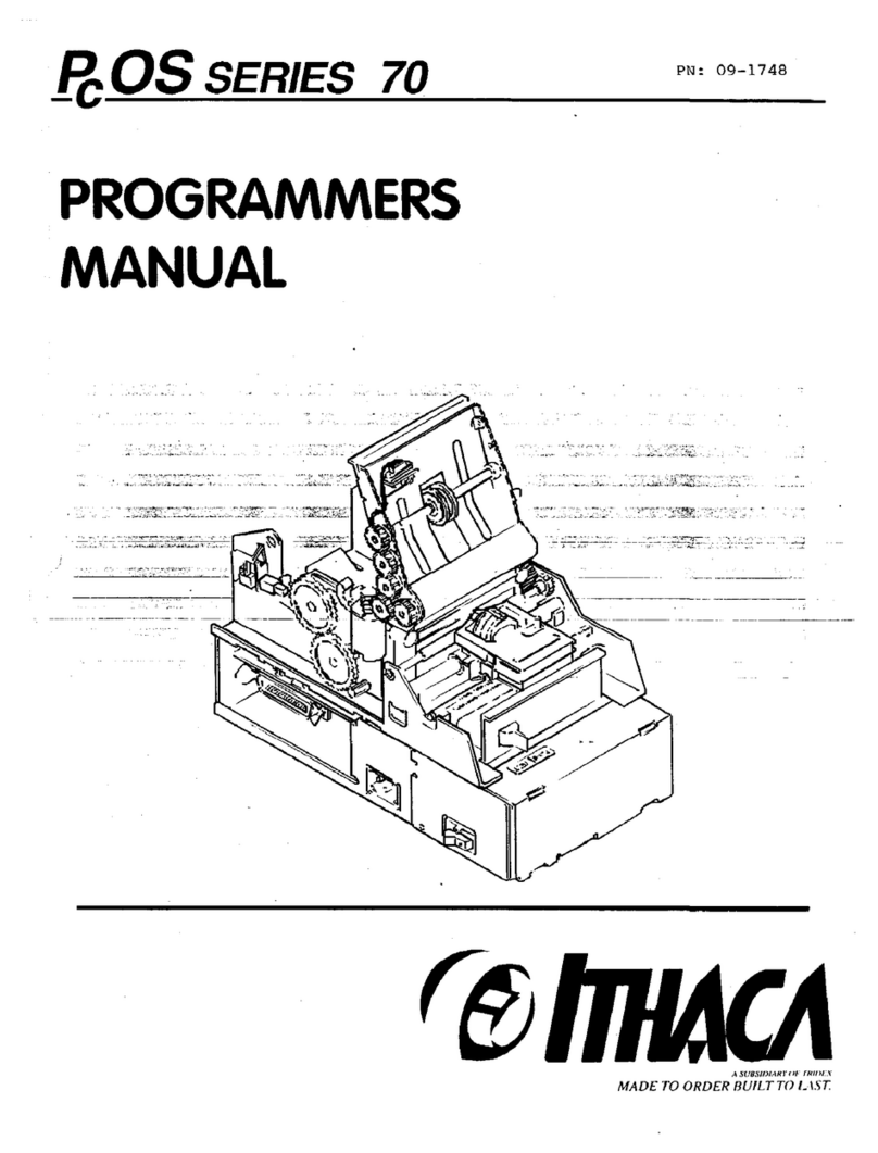
Ithaca 75 User manual

i
Disclaimer
Information in this publication is subject to change without notice and does not
represent a commitment on the part of Ithaca Peripherals Incorporated.
However, as product improvements become available, Ithaca Peripherals will
make every effort to provide updated information for the products described in
this publication.
Ithaca Peripherals cannot guarantee that changes in software and equipment
made by other manufacturers, and referred to in this publication, do not affect
the applicability of the information in this publication.
Copyright
Copyright © 1995
Ithaca Peripherals Incorporated
A Subsidiary of Tridex Corporation
Ithaca, New York U.S.A.
All Rights Reserved. No part of this publication may be reproduced, stored in a
retrieval system, or transmitted, in any form or by any means, mechanical,
photocopying, recording, or otherwise, without the prior written permission of
Ithaca Peripherals Incorporated.
First Edition, April 1995
Printed in U.S.A.
Trademarks
PcOS® is a registered trademark of Ithaca Peripherals Incorporated. Ithaca
Peripherals Incorporated is a subsidiary of Tridex Corporation.

ii
Federal Communications Commission
Radio Frequency Interference Statement
This equipment complies with the limits for a Class A computing device in
accordance with the specifications in Part 15 of FCC rules which are designed
to minimize radio frequency interference in the installation; however, there is no
guarantee that radio or television interference will not occur in any particular
installation. If this equipment does cause interference to radio or television
reception, which can be determined by turning the equipment off and on while
the radio or television is on, the user is encouraged to try to correct the
interference by one or more of the following measures:
♦Reorient the radio or television receiving antenna;
♦Relocate the printer with respect to the receiver;
♦Move the printer away from the receiver;
♦Plug the printer into a different outlet so that the printer and the receiver are
on different outlets.
If necessary, the user should consult the dealer or an experienced
radio/television technician for additional suggestions. The user may find the
following booklet prepared by the Federal Communications Commission
helpful: How to Identify and Resolve Radio/TV Interference Problems.
This booklet is available from the U.S. Government Printing Office,
Washington, DC 20402. Order stock number 004-000-00345-4.

Table of Contents iii
TABLE OF CONTENTS
PRODUCT INFORMATION 1
Communication Interfaces ..........................................................................2
Parallel Interface................................................................................2
Serial Interface...................................................................................2
Technical Specifications.............................................................................4
Performance and Reliability ...............................................................4
Printing..............................................................................................4
Physical Dimensions ..........................................................................4
Environmental Operating Limits.........................................................5
Power Requirements...........................................................................5
Consumable Products.........................................................................5
MAINTENANCE 7
Necessary Tools.........................................................................................7
Lubricating the Printer................................................................................8
Lubricating the Journal Take-up Gears and Pressure Roll Bearing ......8
Lubricating the Auto Cutter Assembly................................................9
Lubricating the Transport-Auto Cutter Assembly .............................10
Cleaning the Printer..................................................................................11
Making Adjustments.................................................................................11
Diagnosing the Print Quality ............................................................12
Adjusting the Platen Parallel to the Printhead....................................13
Adjusting the Platen Air Gap............................................................15
Replacing the Feed Roll Shaft ..........................................................17

Series 70 Maintenance Manualiv
DISASSEMBLY 19
Necessary Tools.......................................................................................19
Transport-Auto Cutter Assembly..............................................................20
Removing the Transport-Auto Cutter Assembly................................20
Disassembling the Transport-Auto Cutter Assembly.........................22
Auto Cutter Assembly (Without Transport) ..............................................26
Removing the Auto Cutter Assembly................................................26
Disassembling the Auto Cutter Assembly .........................................28
Base Assembly.........................................................................................30
AC Switch Assembly and Power Transformer...........................................32
Serial Interface Board...............................................................................34
Control Board ..........................................................................................36
Interconnect Board ...................................................................................38
Journal Bucket Assembly..........................................................................40
Removing the Journal Bucket Assembly ...........................................40
Disassembling the Journal Bucket Assembly.....................................42
Carriage Assembly...................................................................................44
Space Motor Assembly ....................................................................44
Carriage Shaft Bearing and Space Rack ...........................................46
Feed Roll Shaft.........................................................................................48
Linefeed Motor Assembly.........................................................................50
TROUBLESHOOTING 53
Determining the Problem ..........................................................................53
Fixing the Problem ...................................................................................54
Checking Connections and Resistance.......................................................72
Printhead .........................................................................................72
Space Motor Assembly ....................................................................73
Linefeed Motor ................................................................................74

Table of Contents v
APPENDIX A: SPARE PARTS 75
Standard Printer Parts ..............................................................................75
Optional Auto Cutter Parts.......................................................................77
APPENDIX B: THEORY OF OPERATION 79
Electrical Operation..................................................................................79
Circuit Operation.............................................................................79
Initialization.....................................................................................80
Communication Interface Control.....................................................80
Printhead Drive Circuit ....................................................................81
Carriage Drive.................................................................................82
Linefeed...........................................................................................83
Alarm Circuits.................................................................................84
Power Supply ..................................................................................84
Mechanical Operation...............................................................................85
Printhead Mechanism and Operation ................................................85
Space Mechanism and Operation......................................................86
Ribbon Feed Mechanism and Operation............................................86
Paper Feed Mechanism and Operation..............................................87
Paper-Low Detection Mechanism and Operation...............................87
APPENDIX C: SCHEMATICS 89
Control Board ..........................................................................................90
Serial Interface Board...............................................................................94
Interconnect Board ...................................................................................96
INDEX 97


Product Information 1
PRODUCT INFORMATION
Figure 1: Series 70 Printer
The Series 70 Printer models are 40-column, high-speed, impact printers and
are available in the following configurations.
Series 70
Models Receipt
Printing Journal
Printing Paper
Low
Switch
Transport-
Auto
Cutter
Option
Auto
Cutter 6.0 Inch
Receipt
Roll
Option
Model 75 √√ √√ √√ √√ √√
Model 76 √√ √√ √√ √√ √√

Series 70 Maintenance Manual2
COMMUNICATION INTERFACES
Parallel and serial communication interfaces are available.
PARALLEL INTERFACE
Figure 2: Connector for Parallel Interface
The parallel interface is standard on all models and is compatible with
Centronics.
SERIAL INTERFACE
Figure 3: Connector for Serial Interface
The RS-232C serial interface is optional on all models.

Product Information 3
Figure 4: RS-232C Interface Board
RS-232C Specifications:
♦2k Buffer
♦19.2k Baud Maximum
♦Read/Busy or XON/XOFF
♦Diagnostic Mode

Series 70 Maintenance Manual4
TECHNICAL SPECIFICATIONS
PERFORMANCE AND RELIABILITY
Performance
Print Speed Line Feed Time
196 Characters per Second 80 ms at Eight Lines per Inch
Reliability
Mean Time Between
Failure (MTBF) Mean Time To
Repair (MTTR) Print Head Life
25,000 Hours 15 Minutes 200 Million
Characters
PRINTING
Characters
Character Matrix Characters Per Line
7 x 7 Dot Utility Printing 40 at 17.1 Characters per Inch
24 at 10 Characters per Inch
28 at 12 Characters per Inch
Graphics
All Points Addressable (H x V) Bi-Directional Bit Image Graphics
60 x 72 Dots per Inch
120 x 144 Dots per Inch 8 Bit Double Density
PHYSICAL DIMENSIONS
Width Depth Height Weight
6.06 Inches 10.75 Inches 6.75 Inches 13 Pounds

Product Information 5
ENVIRONMENTAL OPERATING LIMITS
Temperature Relative Humidity
40-105° F
5-40° C 20-90%
POWER REQUIREMENTS
Voltage Frequency Operating Power
120, or 220/240 +/- 10% 50/60 Hz +/- 2% 37 Watts
CONSUMABLE PRODUCTS
Paper Number of Plies Dimensions
Receipt, Journal Paper (3.5 Inch
Diameter) One or Two Ply Width: 3.25 Inches
Diameter: 3.50 Inches
Receipt Paper (6.0 Inch
Diameter) One Ply Width: 3.25 inches
Diameter: 6.0 inches
Ithaca Peripherals
Part Number Number
of Plies Rolls Per
Carton Length Color
100-1667 (3.5 Inch
Diameter) One 50 240 Feet White
98-0558 (3.5 Inch
Diameter) Two 50 125 Feet White, Canary
100-2377 (6.0 Inch
Diameter) One 16 765 Feet White
Ribbon Cassette (12 per Box)
Ithaca Peripherals
Part Number Type Color
06-0560 Re-Inking Cassette Black
100-1823 Re-Inking Cassette Purple

Series 70 Maintenance Manual6

Maintenance 7
MAINTENANCE
NECESSARY TOOLS
Caution: Using the wrong tools may cause personal injury or damage the
printer. Be sure to use the proper tools when maintaining or
servicing the Series 70 Printer.
The following table provides the necessary tools needed to properly maintain
the Series 70 Printer.
Nut Drivers Screwdrivers Ignition
Wrenches Miscellaneous
7/32 Inch #0 Phillips 7/32 Inch Thickness Gauge: .012 Inch
1/4 Inch #1 Phillips 1/4 Inch AllenWrench: .050 Inch
9/32 Inch #2 Phillips Hobby Knife
5/16 Inch Regular, Small Small Needle-Nose Pliers
3/8 Inch Regular, Large Paper Clip
7 mm

8Series 70 Maintenance Manual
LUBRICATING THE PRINTER
No periodic lubrication is required under normal printer use. Some lubrication
may be required with heavy printer use.
Caution: DO NOT use petroleum-based lubricants as they will damage the
plastic parts. Use a silicone-based lubrication.
Caution: Lubricating any points other than described here, such as the Space
Rack, will cause early and expensive failures to the printer.
LUBRICATING THE JOURNAL TAKE-UP GEARS AND
PRESSURE ROLL BEARING
Figure 5: Lubricating the Journal Take-up Gears and Pressure Roll Bearing
A = Journal Take-up Gears B = Pressure Roll Bearing
Lubricate the following points only:
♦Journal Take-up Gears
When: as needed
♦Pressure Roller Bearing
When: as needed

Maintenance 9
LUBRICATING THE AUTO CUTTER ASSEMBLY
Figure 6: Lubricating the Auto Cutter Assembly
A = Guide Wheel B = Pins for Shear Plate
Lubricate the following points only:
♦Guide Wheel
When: every six months or 100,000 cycles
♦Pins for Shear Plate
When: every six months or 100,000 cycles

10 Series 70 Maintenance Manual
LUBRICATING THE TRANSPORT-AUTO CUTTER ASSEMBLY
Figure 7: Lubricating the Transport-Auto Cutter Assembly
A = Guide Wheel B = Pins for Shear Plate

Maintenance 11
For ease in lubricating the Transport-Auto Cutter Assembly, remove it from the
printer. See “Transport-Auto Cutter Assembly” in the “Disassembly” chapter.
Lubricate the following points only:
♦Guide Wheel
When: every six months or 100,000 cycles
♦Pins for Shear Plate
When: every six months or 100,000 cycles
CLEANING THE PRINTER
Remove paper dust periodically by using a vacuum cleaner or air compressor.
Caution: Do not use alcohol or petroleum-based chemicals to clean the printer
as these will damage the plastic parts. The Carriage Rack is
particularly sensitive and will be permanently damaged if exposed to
these chemicals. Take special care not to get the cleaner on any
electronic components.
MAKING ADJUSTMENTS
The adjustments described in this section are required only to correct Printhead
drag or print quality flaws.
If the print density on a print sample is consistent from left to right and top to
bottom, and the Printhead does not drag, no adjustment is necessary. If the
Printhead drags, the gap may be too narrow. Increase the gap in order to get the
proper air gap of .012 inch on both left and right sides.
After a period of use, the Feed Roll Shaft may wear down to a point where
adjusting the gap will not correct the print problem. In this case, the Feed Roll
Shaft needs to be replaced. The Feed Roll Shaft also needs to be replaced when
it is cracked or “weather checked.” Refer to “Replacing the Feed Roll Shaft”
later in this chapter.
Note: Any time the Feed Roll Shaft is replaced, the bearings on either end
must also be replaced.
Check the Platen Air Gap and readjust it if necessary. See “Adjusting
the Platen Parallel to the Printhead” and “Adjusting the Platen Air
Gap” later in this chapter.

12 Series 70 Maintenance Manual
DIAGNOSING THE PRINT QUALITY
Use the flowchart on the following page to determine which procedure to use to
correct the specified print problems.
Figure 8: Flowchart for Print Quality Diagnosis
Note: If a print problem is not covered in this flowchart, refer to the
troubleshooting chart on page 53.
This manual suits for next models
1
Table of contents
Other Ithaca Printer manuals

Ithaca
Ithaca POSjet 1000 Manual

Ithaca
Ithaca KitchenJet 1000 User manual

Ithaca
Ithaca Epic 950 Use and care manual

Ithaca
Ithaca PcOS series 90plus User manual

Ithaca
Ithaca POSjet 1000 User manual

Ithaca
Ithaca Series 70 Manual

Ithaca
Ithaca PcOS series 90plus Manual

Ithaca
Ithaca PcOS 80 Series User manual

Ithaca
Ithaca PcOS series 90plus Manual

Ithaca
Ithaca PcOS Series 80PLUS Manual