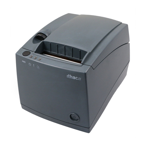
Ithaca POSjet 1000 Manual

jet™1000
OPERATOR’S
GUIDE
PN: 12-02396
Rev C
Jan-01

Revision C
Rev A Initial Release
Rev B Corrected part numbers for parts list. Added Tech Support Info. Expanded all sections to make an Installation and a Operational
section. Re-organized information. Updated Content. Updated Charts and Figures tables. Updated and expanded Index listings.
Rev C New Keypad drawing. New Cable Restraint drawing. Corrected serial interface pin assignments. Included new Operational
Troubleshooting keypad drawings. Added Environmental graph. General content updates and corrections.

Information in this publication is subject to change without notice. However, as product improvements become
available, TransAct Technologies Incorporated will make every effort to provide updated information for the
products described in this publication. TransAct Technologies Incorporated cannot guarantee that changes in
software and equipment made by other manufacturers, and referred to in this publication, do not affect the
applicability of information in this publication.
The POSjet™1000 Printer complies with the limits for a Class A computing device in accordance with the
specifications in Part 15 of FCC rules. These regulations are designed to minimize radio frequency interference
during installation; however, there is no guarantee that radio or television interference will not occur during any
particular installation. Interference can be determined by turning the equipment off and on while the radio or
television is on. If the printer causes interference to radio or television reception, try to correct the interference by
one or more of the following measures:
1. Reorient the radio or television receiving antenna
2. Relocate the printer with respect to the receiver
3. Plug the printer and receiver into different circuits
If necessary, the user should consult their dealer or an experienced radio/television technician for additional
suggestions. The user may find the following booklet prepared by the Federal Communications Commission helpful:
How to Identify and Resolve Radio/TV Interference Problems. This booklet is available from the US Government
Printing Office, Washington, DC 20402. Ask for stock number 004-000-00345-4.
The POSjet™ 1000 Printer does not exceed Class A limits for radio noise emissions from digital apparatus set out in
the Radio Interference Regulations of the Canadian Department of Communications.
FCC Class A
ULc
CE Mark
UL 1950
TUV
2000 TransAct Technologies Incorporated. All rights reserved.
Revision Level C
December, 2000
Printed in USA
PcOS and POSjet™ are registered trademarks of Transact Technologies Incorporated. Ithaca®is a registered trademark of TransAct \
Technologies. IBM is a registered trademark of the International Business Machines Corporation. Epson and ESC/POS are registered trademarks
of the Seiko Epson Corporation. Microsoft, Windows, Windows NT, and Plug and Play are trademarks of the Microsoft Corporation. Patents
Pending. Microline is a registered trademark of OKI Electric Industry Co., LTD.

Monday through Friday, 8 A.M. to 5 P.M. (excluding holidays).
To obtain Technical Support, call: TransAct's Ithaca Facility at (607) 257-8901, or (877) 7ithaca.
TransAct Technologies Incorporated has a full service organization to meet your printer service and repair
requirements. If your printer needs service, please contact your authorized printer service center. If any problems still
persist, you can directly contact the Ithaca Facility’s Technical Support Department at (607) 257-8901 or (877)
7ithaca for a return authorization. International customers should contact your distributor for services. TransAct
offers the following service programs to meet your needs.
Extended Warranty
Depot Repair
Maintenance Contract
Internet Support
Please have the following information at hand:
1. The Model Number and Serial Number.
2. A list of any other peripheral devices attached to the same port as the printer.
3. The application software, operating system, and network you are using.
4. A copy of your printer’s Configuration Settings.
5. What happened and what you were doing when the problem occurred.
6. How you tried to solve the problem.
TransAct’s POSjet™1000 Printers come with a standard 24-month warranty that commences upon shipment from
factory, and covers parts and labor. An optional warranty, covering both parts and labor for an additional 12 months,
may be purchased separately. Repairs are warranted for 90 days from the date of repair or for the balance of the
original warranty period, which ever is greater.
! "
If the technical support person determines that the printer should be serviced at our facility, and you want to return
the printer for repair, a Returned Materials Authorization (RMA) number must be issued before returning the printer.
Prepare the printer being returned for repair as follows:
1. Remove and discard ink cartridges.
2. Return all materials in the original packing. Packing items may be purchased from TransAct's Ithaca Facility.
3. Return only the accessories that a Support Technician asks you to include.
4. Write the RMA number clearly on the outside of the box.
Never ship a printer by any means with any ink cartridge(s) installed. Be sure to save the packing
materials in the event that you need to send the printer in for servicing. TransAct Technologies is not responsible for
damaged return items that are not packaged in original shipping material.

#
www.transact-tech.com
TransAct Technologies Incorporated maintains an internet web site with content devoted to supporting our products.
Within the Support Services Section you can find documentation for the POSjet™ 1000 Printer, including a current
copy of the Operator’s Guide and Programmer’s Guide. The technical support page contains support information
for our printers. The POSjet™ 1000 Printer support pages offer the latest information. They include the current
version of most manuals.
$ %
The Programmer’s Guide is available by down loading it from our web site and is intended for system engineers or
integrators. It does not contain additional information on the Microline Emulation. It contains the information to
integrate the POSjet™ 1000 Printer with a point-of-sale terminal and to program the terminal to communicate with
the printer in PcOS or ESC/POS mode.
Start-up Information-Diagnostics and Fault Conditions
Command Descriptions
Character Fonts
Printer Features
Parallel and RS-232 Interface Information
Communications and Buffers
Command Code Reference Tables
& '
POSjet™ 1000 Drivers and Utilities can be downloaded from our web site, or call our Technical Support
Department to request a Software Developer’s Toolkit (CD-ROM).
!
100-02440
'
Windows® 95/98/Me Print Driver and Documentation 98-9171
Windows® 2000/NT 4.0 Print Driver and Documentation 98-9172
OPOS Print Driver Manual 100-9730
OPOS Print Driver Disk 1 100-9731
OPOS Print Driver Disk 2 100-9732
& '
"# $ %&
POSjet Image Converter (PJColor) is a tool to help develop graphic images to use as logos and coupons on the
printer. It will read and convert images to a format suitable for printing on the POSjet™ 1000 printer. It will allow
you to preview the image and adjust the colors prior to printing. It will also allow the images to be stored in the
printer's User Store.
' %&
PJTerminal is a tool that has been developed to allow you to interactively send commands to and get responses from
the printer.

Contact TransAct’s Ithaca facility for information about the POSjet™ 1000 Printer and how it works with your
system. For information on International distribution, visit our web site at www.transact-tech.com. Contact the
TransAct’s Sales and Technical Support Departments at the following address and telephone
or fax numbers.
Receive technical support, order documentation, request additional information, or send in a printer for service.
Order supplies, receive more product information, or order product brochures.
Ithaca Facility
20 Bomax Drive
Ithaca, NY 14850 USA
Telephone (877) 7ithaca or (607) 257-8901
Main fax (607) 257-8922
Sales fax (607) 257-3868
Technical Support fax (607) 257-3911
Web site http://www.transact-tech.com

#$ %(
This Operator’s Guide is organized in two sections. The first section covers proper installation and setup procedures,
and the second includes information on using the printer.
Chapter 1 includes a five-step process that provides the required information
to setup the POSjet™ 1000 for the first time.
Chapter 2 lists several potential problems that may be experienced during
and after the installation process is completed. This information is listed by problem type
and gives the possible cause and remedy for each listing.
!"# $$$
Chapter 3 provides the specifications for the POSjet’s installation and proper usage.
Topics include interface requirements, operating conditions, power requirements, and
print characteristics.
!
% & ' (
Chapter 4 includes information on the POSjet’s keypad buttons and indicator lights and
explains how fault indicators work.
) ! * &
$
Chapter 5 explains the difference between one cartridge and two cartridge printing and
provides information on how each printing option influences the configuration settings of
the printer. Ink cartridge care and status are also covered, and several keypad displays
show how the indicator lights represent cartridge status.
+ ,
Chapter 6 gives a basic overview of what self-test is and how to use it to test the
functionality of your printer.
- ,
Chapter 7 gives an explanation of configuration mode and explains how the new
cartridge button is used to change and save configuration settings.
( %
Chapter 8 provides parallel and serial requirements, and also gives pin assignments. It
also covers cash drawer driver interface specifics like the interface card and shunt
positioning for the Star, Ithaca®, and Epson emulations.
. ! +
Chapter 9 lists troubleshooting procedures for the most frequently occuring problems
that a user will experience while operating the POSjet™ 1000.
/0 / ! .
Ordering supplies.
!"
#" $
# %
%
$
$
% &'" (
/0 1 , 23 /* 4
$
Most frequently asked questions.
Table 1 Where to find specific information

Change History................................................................................................................................................................................................................... i
Disclaimer .......................................................................................................................................................................................................................... i
Federal Communications Commission Radio Frequency Interference Statement............................................................................................................... i
Canadian Department of Communications Radio Interference Statement.......................................................................................................................... i
Regulatory Compliance...................................................................................................................................................................................................... i
TransAct Product Support ................................................................................................................................................................................................. ii
Service Information ........................................................................................................................................................................................................... ii
Warranty Information........................................................................................................................................................................................................ ii
Return Materials Authorization and Return Policies......................................................................................................................................................... ii
Shipping Printers............................................................................................................................................................................................................... ii
5 6 2 , 7
Our Internet Support and Sales Services........................................................................................................................................................................... iii
Programmer’s Guide.........................................................................................................................................................................................................iii
Drivers and Utilities Available......................................................................................................................................................................................... iii
Drivers Available..............................................................................................................................................................................................................iii
Utilities Available.............................................................................................................................................................................................................iii
/8 29
Technical Support..............................................................................................................................................................................................................iv
Sales ..................................................................................................................................................................................................................................iv
TransAct Technologies Incorporated.................................................................................................................................................................................iv
What is covered in this Operator’s Guide?.........................................................................................................................................................................v
9
Figures...............................................................................................................................................................................................................................ix
Tables ................................................................................................................................................................................................................................ix
&*
:
Connecting the AC Power Cord (with power supply).........................................................................................................................................................3
Connecting the DC Power Cord (no power supply)............................................................................................................................................................4
Using the Cable Restraints .................................................................................................................................................................................................4
Connecting the Communication Cable...............................................................................................................................................................................5
Connecting the Cash Drawer..............................................................................................................................................................................................6
;: -
Adjusting the Paper-Low Sensor ........................................................................................................................................................................................7
Paper Low Adjustment Requirements ................................................................................................................................................................................8
% ; * .
Installing Ink Cartridges .....................................................................................................................................................................................................9
Installing a New Paper Roll Using Insta-Load™..............................................................................................................................................................10
)
Correcting Common Startup Problems.............................................................................................................................................................................12
!"
$$$
Dimensions.......................................................................................................................................................................................................................13
Interface............................................................................................................................................................................................................................13
Printer...............................................................................................................................................................................................................................13
Paper Dimensions.............................................................................................................................................................................................................13
Reliability.........................................................................................................................................................................................................................13
Power Requirements.........................................................................................................................................................................................................14
External Powered DC .......................................................................................................................................................................................................14
Print Characteristics .........................................................................................................................................................................................................14
Environmental Conditions................................................................................................................................................................................................15
Relative Humidity.............................................................................................................................................................................................................15
Paper and Core Diameter..................................................................................................................................................................................................16
% & ' (
Operating the Keypad.......................................................................................................................................................................................................18
Keypad Controls...............................................................................................................................................................................................................19
Keypad Indicator Light Descriptions................................................................................................................................................................................19
) ! * &$
Overview of Color Ready Option .....................................................................................................................................................................................20
Color Ready Configuration...............................................................................................................................................................................................20
Single Ink Cartridge Operation.........................................................................................................................................................................................20
Single Cartridge Operation (Color-Ready Configuration)................................................................................................................................................20
Two Cartridge Operation..................................................................................................................................................................................................20
Feature Configuration.......................................................................................................................................................................................................20
Using Ink Cartridges.........................................................................................................................................................................................................20
Care of Ink Cartridges ......................................................................................................................................................................................................20

Determining Ink Cartridge Status.....................................................................................................................................................................................21
+ ,
Placing the Printer In Self-Test Mode...............................................................................................................................................................................22
Exiting Self-Test Mode.....................................................................................................................................................................................................22
Self-Test Hints and Suggestions.......................................................................................................................................................................................22
- ,
Changing Printer Configuration .......................................................................................................................................................................................23
Placing the Printer In Configuration Mode (Manual Configuration Mode)......................................................................................................................23
Using the New Cartridge Button in Configuration Mode.................................................................................................................................................23
( %
Parallel Interface...............................................................................................................................................................................................................24
Parallel Pin Assignments..................................................................................................................................................................................................24
Serial Interface..................................................................................................................................................................................................................24
Serial Pin Assignments.....................................................................................................................................................................................................24
Cash Drawer Interface Description and Specifics.............................................................................................................................................................25
Cash Drawer Pin Assignments..........................................................................................................................................................................................25
. ! +
Keypad Indicator Troubleshooting Chart..........................................................................................................................................................................26
Serious Problems Indicator Warnings...............................................................................................................................................................................26
Ordering Supplies.............................................................................................................................................................................................................29
Paper.................................................................................................................................................................................................................................29
Ink Cartridges...................................................................................................................................................................................................................29
Cables...............................................................................................................................................................................................................................29
! " # $%

Figure 1 Unpacking Instructions.........................................................................................................................................................................................2
Figure 2 Connecting the AC Power Cord (with power supply)...........................................................................................................................................3
Figure 3 Connecting the DC Power Cord (no power supply)..............................................................................................................................................4
Figure 4 Connecting Serial Cable.......................................................................................................................................................................................5
Figure 5 Connecting Parallel Cable....................................................................................................................................................................................5
Figure 6 Connecting Cash Drawer......................................................................................................................................................................................6
Figure 7 Paper Low Setup (adjusting the sensor)................................................................................................................................................................7
Figure 8 Installing Ink Cartridges.......................................................................................................................................................................................9
Figure 9 Installing New Paper Roll...................................................................................................................................................................................10
Figure 10 Environmental Conditions................................................................................................................................................................................15
Figure 11 Paper Roll and Paper Core Diameters ..............................................................................................................................................................16
Figure 12 Keypad Buttons and Indicator Lights...............................................................................................................................................................18
Figure 13 Cash Drawer Pin-outs.......................................................................................................................................................................................25
'
Table 1 Where to find specific information........................................................................................................................................................................v
Table 2 Paper Low Setup....................................................................................................................................................................................................8
Table 3 Troubleshooting: Nothing Happens at Startup.....................................................................................................................................................12
Table 4 Troubleshooting: Printer Communications Failure..............................................................................................................................................12
Table 5 Troubleshooting: Ink Cartridge Status Indicator Flashing ...................................................................................................................................12
Table 6 POSjet Power Requirements................................................................................................................................................................................14
Table 7 Power Input Requirements Optional 24-volt DC Supplied from Host.................................................................................................................14
Table 8 POSjet Print Characteristics ................................................................................................................................................................................14
Table 9 Using Buttons Quick Reference Table.................................................................................................................................................................18
Table 10 Keypad Indicators: Ink Cartridge Status............................................................................................................................................................21
Table 11 How to Change Configuration Settings.............................................................................................................................................................23
Table 12 Parallel Interface Pin-outs..................................................................................................................................................................................24
Table 13 Serial Interface Pin-outs.....................................................................................................................................................................................24
Table 14 Keypad Indicators: General Problems................................................................................................................................................................26
Table 15 Keypad Indicators: Serious Problems ................................................................................................................................................................26
Table 16 Troubleshooting: Keypad Lights Will Not Work...............................................................................................................................................27
Table 17 Troubleshooting: Printer Will Not Print (Error Light ON).................................................................................................................................27
Table 18 Troubleshooting: Printer Will Not Print (Error Light OFF) ...............................................................................................................................27
Table 19 Troubleshooting: Printer Prints With Missing Dots in Characters.....................................................................................................................28
Table 20 Troubleshooting: Printer Sounds Like It’s Printing But Nothing Prints.............................................................................................................28
Table 21 Troubleshooting: Printer Will Not Load or Feed Paper......................................................................................................................................28
Table 22 Paper Ordering Information...............................................................................................................................................................................29
Table 23 Ink Cartridge Ordering Information...................................................................................................................................................................29
Table 24 Cables Ordering Information .............................................................................................................................................................................29
Table 25 Most Frequently Asked Questions.....................................................................................................................................................................30

Section 1
Installation and Startup Information
!"##"
By following the instructions in this section, the POSjet™1000 will be ready to accept commands and successfully
interface with your system in just a few minutes. Follow the steps below when setting up your printer.
Step 1: Unpack the Printer ............................................................................................ pg. 2
Step 2: Connect Power and Communications................................................................ pg. 3
Step 3: Paper Low Setup................................................................................................ pg. 7
Step 4: Loading Ink Cartridges and Paper ..................................................................... pg. 9
Step 5: Confirm Configuration Settings......................................................................... pg. 11
Chapter 2: Installation and Setup Troubleshooting........................................................ pg. 12
Chapter 3: POSjet™1000 Specifications...................................................................... pg. 13

" !$%
Be sure to save the box and packing materials in case you need to send the printer in for service. Transact
Technologies is not responsible for damaged return items that are not packaged in original shipping material. Refer
to “Return Materials Authorization and Return Policies”, on page ii for information on what to do if you have to
return your printer for repair.
1. Open the box and remove the printer and all items. Check to make sure that all items are present.
POSjet™ 1000 Printer
Ink Cartridge(s)
Paper Roll (located under the rear paper cover)
PowerPocket™ Power Supply located in cabinetry base (optional)
AC Power Cord (optional)
2. Separate the printer from the packing material. Reverse steps when repacking for return shipment.
3. Check the printer for any signs of damage. If the printer or any parts are damaged, report it to your supplier and
shipper immediately.
Be sure to save the box and packing materials in case you need to send the printer in for service. (You will not need
to repack the supplies).
Figure 1 Unpacking Instructions

"&!'
) *) ) +
1. Orientate the printer upside-down and find the POSjet’s power supply’s power socket.
2. Locate the power cord and connect it to the power socket (power supply) located on the back of the printer and
to an external AC power outlet. The socket-outlet shall be installed near the equipment and shall be easily
accessible.
3. Route the power cord through the cable restraints. Refer to the drawing below to see how to route cord. Failure
to use the cable restraints may result in the printer becoming accidently unplugged during operation.
4. Turn on the printer by pressing the
button. The printer takes 1.5 seconds to begin operation.
Figure 2 Connecting the AC Power Cord (with power supply)

Interface Card
Cash Drawer
Harness
Power Cord
Cable Restraints Communication Cable
Cash Drawer
Restraint
) * ) +
1. Orientate the printer upside-down and find the DC power socket on the side of the interface card (PCB).
2. Locate the DC power cord and connect it to the interface card’s power socket, then route the cord through the
cable restraint. Failure to use the cable restraints may result in the printer becoming accidently unplugged during
operation.
3. Turn on the printer. Press the
button. The printer takes 1.5 seconds to begin operation.
Figure 3 Connecting the DC Power Cord (no power supply)
& '
Cable restraints have been developed to protect against accidental unplugging of the printer while it is in use. Be sure
to properly route the communications cable using the restraints provided on the back of the printer.
1. Orientate the printer upside-down and locate the cash drawer restraint. The cash drawer restraint is offset from
the middle of the cabinetry base.
2. Plug the cash drawer harness into the connector on the printer’s interface card.
3. Route the harness through the cash drawer cable restraint, then position it between the two remaining cable
restraints and connect it to your system.

'
Depending on the interface your system uses, either connect the serial or parallel communication cable to the
appropriate connector on the back of the printer. Cables are provided by your dealer or system installer. If cables are
unavailable, see “Contacting TransAct’s Ithaca Facility”, on page iv.
$ $
1. Use the
button to turn off the printer. Also turn off your host system or personal computer.
2. Connect the 9/25-pin serial interface cable to the connector located on the back of the printer.
Refer to “Serial Interface”, on page 24 for information on the serial cable requirements.
3. Tighten the two mounting screws on each side of the cable connector.
4. Route the communication cable through the cable restraint and connect the cable to your host system.
Refer to the drawing for “Using the Cable Restraints”, on page 4.
Figure 4 Connecting Serial Cable
$ $
1. Use the
button to turn off the printer and host system or personal computer.
2. Connect the 25/36-pin parallel interface cable to the connector located on the back of the printer.
Refer to “Parallel Interface”, on page 24 for more information on parallel connection requirements.
3. Tighten the two mounting screws on each side of the cable connector (25 pin only). Or, engage the
locking clips (36 pin only).
4. Route the communication cable through the cable restraint and connect to your host system. Refer to the
drawing for “Using the Cable Restraints”, on page 4.
Figure 5 Connecting Parallel Cable

)
Check the CAUTION label on the bottom of printer. This label indicates the cash drawer
configuration setting that shipped with the printer. There will be either an Ithaca, Star, or Epson
compatability sticker on your printer. Verify that the label’s configuration matches the cash drawer
in your application.
The POSjet™ 1000 Printer supports dual cash drawers with status.
The Cash Drawer can be configured for one of three settings. The interface card has a 14-pin header with a 10-pin
shunt installed on it. The shunt position defines the configuration of the cash drawer. Refer to the markups on the
board when determining where the shunt should be installed to work in the three different configurations. Refer to
“Cash Drawer Interface Description and Specifics”, on page 25 for information on how to install the cash drawer.
$ $ $
1. Use the
button to turn the printer off.
2. Orientate the printer so you are looking at the rear underside of the unit and locate the small cash drawer
connector to the left of the communication connector.
3. Connect the cash drawer cable to the connector located on the back of the printer, making sure that the cash
drawer cable snaps into place.
Figure 6 Connecting Cash Drawer
(

Factory Setting:
The factory setting leaves
room for adjusting the Paper
L
ow Sensor up or down by
three full turns with a screw
driver.
Upper Limit Setting:
When adjusted, the sensor
will move up and away from
the Cabinetry Base. Do not
adjust anymore than 3 turns
counter clockwise from the
mid-position setting.
Lower Limit Setting:
When adjusted, the sensor
moves down and toward the
Cabinetry Base. Do not
adjust anymore than 3 turns
clockwise, from the
mid-position setting.
")!*'"
All printers ship with a factory default, mid-position setting that can be adjusted up or down with 1 to 3 full turns of
the adjustment screw. The amount of paper remaining after paper low detection is dependent on this adjustment.
Generally, in most cases the paper low setup does not need to be changed from the factory setting.
, -.)
1. Open the rear paper cover and locate the paper low adjustment access hole.
2. Refer to Table 2 on the following page for specific adjustment settings.
3. Turn screw to control the amount of paper that is remaining after paper low has occurred.
CAUTION: When the sensor touches the plastic of the cabinetry base (lower limit only), the sensor should not be
adjusted any further. Over adjustment will cause stress in the sensor material and will decrease its longevity.
Figure 7 Paper Low Setup (adjusting the sensor)

.) ,
Use the following table to decide how much paper you want to remain after paper low sensing has occurred.
TransAct’s expected results are based on paper and paper roll with these specifications.
;: /" /0 < = >
& ? ;,
24' 1.420" (36mm)
22'1.375" (34.9mm)
16’ 1.250" (31.7mm)
2/!6 ?@A
12' 1.175" (29.8mm)
7'1.050" (26.6mm)
3.5'.950" (24.1mm)
;!5 ;,
1.25' .885" (22.4mm)
Table 2 Paper Low Setup
Refer to “Chapter 3: POSjet™ 1000 Specifications”, on page 13 for paper measurements.
Refer to “Paper and Core Diameter”, on page 16 for core dimensions.
Always check that the core is aligned with the right edge of the paper roll, as installed.

Replace with new
cartridge(s) Close Blue Latch
Open Blue Latch Remove Old
Cartridges
Mylar Tape
Round Tab
"+!*%
!"# $% & ' ( & ' ) % ) *+ * %
% % ( &+ % ,
/
The printer should be turned ON by using the
Button before you install ink cartridges. Confirm that the printer is
ON by checking that the power indicator light is activated. Refer to “Chapter 4: Using Keypad Controls”, on page 18
for information on the power indicator light.
Caution: Do not touch ink cartridge’s metallic connector surface with your fingers. Doing so will contaminate the
connector and produce bad print quality.
1. Open the front cover of printer (Opening front
cover automatically opens rear paper cover.)
(NOTE: If paper is present, ensure that receipt
is torn off prior to opening front cover.
2. Pull down blue cartridge latch/latches
3. Remove new ink cartridge from sealed pouch.
(Hold cartridge by round tab to avoid contamination.)
4. Remove mylar tape from face of new ink cartridge.
5. Place new ink cartridge(s) into carriage. Hold round tab
to ensure clean installation. Black cartridges go into left
carriage. Color cartridges go into right carriage. (Round
tab faces to front of printer.) Refer to the drawings
below to see how to install the ink cartridges into carriage.
6. Close blue latch/latches.
7. Press the NEW CARTRIDGE Button. Doing this initializes
the ink status on the newly inserted ink cartridges.
Note: If you are installing the printer, an ink cartridge or cartridges
can be found in the pouch that shipped with your printer.
Figure 8 Installing Ink Cartridges

2
0) & -.1
Before you attempt to load the paper roll, make sure that the printer is plugged in and that the printer is turned ON.
!IMPORTANT!: Paper cannot be loaded for the first time without first installing ink cartridge(s). If this is a
new installation, a small receipt roll is supplied with the printer.
1. Open printer’s rear paper cover. (First time installers will already have the cover open from installing ink
cartridges.)
2. Insert the paper roll so that the paper unwinds from the bottom and rests on the top of the front cover.
3. Make sure paper is to the top front edge of the front cover. This is done to give the printer enough room to
complete the automatic loading process and prepare for operation.
4. Close the rear paper cover. The printer will automatically load the paper through the feeding mechanism. If the
paper does not feed, repeat the steps.
Figure 9 Installing New Paper Roll
Other manuals for POSjet 1000
1
Table of contents
Other Ithaca Printer manuals

Ithaca
Ithaca Series 60 Manual

Ithaca
Ithaca Epic 950 Use and care manual

Ithaca
Ithaca 75 User manual

Ithaca
Ithaca PcOS Series 80PLUS Manual

Ithaca
Ithaca Series 70 Manual

Ithaca
Ithaca PcOS series 90plus Manual

Ithaca
Ithaca ITHERM 280 Quick guide

Ithaca
Ithaca PcOS series 90plus Manual

Ithaca
Ithaca BANK jet 1500 Reference guide

Ithaca
Ithaca KitchenJet 1000 User manual