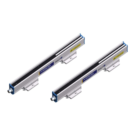
ITW Simco-Ion IQ Power User manual

IQ Power™ BPS 5201197 Rev. D
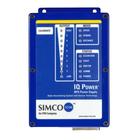
IQ Power™
Static Neutralizing System
with BPS Power Supply
INSTALLATION AND OPERATING INSTRUCTIONS

IQ Power™ BPS 5201197 Rev. D
TABLE OF CONTENTS
1. SAFETY WARNINGS............................................................................ 1
2. DESCRIPTION ................................................................................... 2
Features.................................................................................................................................3
4. SPECIFICATIONS................................................................................ 4
5. INSTALLATION .................................................................................. 6
Initial Considerations..........................................................................................................12
Mounting the Static Neutralizing Bar ................................................................................13
Mounting the Power Supply ...............................................................................................14
Mounting the Communication Module (optional) .............................................................14
Electrical Connections........................................................................................................14
6. OPERATION .....................................................................................22
Power Supply Indicators .....................................................................................................22
Power Supply Operators .....................................................................................................22
System Start-up: .................................................................................................................23
Power Supply Number (Address) .......................................................................................24
Power Supply Number Table ..............................................................................................24
Static Bar Operation ...........................................................................................................25
Communication Module Operation (optional) ...................................................................25
Control Station Operation (optional)..................................................................................26
7. MAINTENANCE AND TROUBLESHOOTING .................................................27
Cleaning the Static Bar.......................................................................................................27
Troubleshooting .................................................................................................................28
8. PARTS AND ACCESSORIES...................................................................30
9. WARRANTY.....................................................................................32

1
IQPower™BPS 5201197Rev.D
1. SAFETY WARNINGS
Simco-Ion recommends that these instructions be read completely before installation or
operation is attempted. Failure to do so could result in personal injury and/or damage to
the equipment.
NOTE – Statements identified with NOTE indicate precautions necessary to avoid
potential equipment failure.
CAUTION – Statements identified with CAUTION indicate potential safety
hazards.
NOTE – This equipment must be correctly installed and properly maintained.
Adhere to the following notes for safe installation and operation:
1. Read instruction manual before installing or operating equipment.
2. Only qualified service personnel are to perform installation and repairs.
3. All equipment must be properly grounded, including the machine frame to which the
equipment is mounted.
4. Disconnect input power to power supply before connecting or disconnecting static
neutralizing bars to the high voltage power supply.
5. Do not operate system in close proximity to flammable liquids.
6. Do not use standard Ethernet cables with IQ Power
TM
Systems.
CAUTION – This product is intended to be supplied by a Listed AC Adapter or
Power Unit marked “Class 2” or “LPS” and rated output 24V from 1.6A to
3.75A.
CAUTION – Electrical Shock Hazard
Disconnect input power to high voltage power supply before connecting or
disconnecting static neutralizing bar or performing any maintenance to the
system. Avoid touching static neutralizing bar when power supply is energized.
CAUTION – Fire Hazard
Do not install or operate static neutralizing bar in close proximity to any
flammable liquids or solvents.

2
IQ Power™ BPS 5201197 Rev. D
2. DESCRIPTION
Simco-Ion’s IQ Power™ Static Neutralizing System consists of a high voltage power
supply, static neutralizing bar, and optional web speed encoder, optional control station
and/or optional computer communication module. The IQ Power™ static bar is available
in three different types; tailored for high speed processes, operating at a distance from the
material or intermediate (hybrid) applications. The IQ Power™ communication module
provides the ability to remotely monitor real time system performance and log operating
data through a computer interface.
The high voltage power supply module provides microprocessor controlled high voltage
DC output to the static bar. The high voltage causes the ionizing pins on the static bar
to generate positive and negative ions. The electric field from the static charge on the
material being processed will attract opposite polarity ions from the static bar causing
the material to be neutralized. The excess ions will either recombine in air or dissipate
to ground.
The static neutralizing bar features current limiting at each individual ion emitting pin to
minimize the risk of hazardous electrical shock if the bar is touched while in operation.
This safety feature does not compromise the IQ Power™ system’s ability to neutralize
static charges. The emitter pins are made of a special alloy to extend the longevity and
sharpness of the points, providing optimal performance of the static bar.
The IQ Power™ static bar is tailored to the application. Speed bars are optimized to
operate on high speed webs at distances of 50 to 230 millimeters [2 to 9 inches]. Hybrid
bars operate at distances of 150 to 460 millimeters [6 to 18 inches] on webs where the
web path is somewhat variable. Distance bars are designed to operate from 300 to 760
millimeters [12 up to 30 inches] to the material. The variety of IQ Power™ static bars
offered allows the user to install the optimum bar for their static neutralizing needs.
The IQ Power™ static bar has a plug-in style high voltage connector for fast and easy
installation. The connector features a pin that “tells” the IQ Power™ power supply what
type IQ Power™ bar is installed and optimizes the power supply output for that type of
bar.
The communication module is designed as a port for an Anybus® CompactCom module.
This module provides interface with a wide variety of standard industrial computer
communication protocols allowing easy integration of the IQ Power™ static neutralizing
system with existing networks.
All IQ Power™ optional modules use 8-conductor modular cable and RJ-45 connectors
for connection to the IQ Power™ system.. They are supplied with 7 foot cable assemblies
but longer lengths are available by calling Simco-Ion customer service (800) 203-3419
(refer to Section 8, Parts and Accessories).
Anybus® CompactCom is a registered trademark of HMS Industrial Networks.
3
IQ Power™ BPS 5201197 Rev. D
Features
• ThreetypesofIQPower™staticneutralizingbarsareavailabletosuitthe
specific application.
• Staticbardisconnectplugpre-installedonstaticbarcableforquickandeasy
installation. Plug also identifies bar type to power supply automating power
supply set-up.
• Singlemomentarypush-buttoncalibrationsimplifiesset-up.
• Ionizationemitterpointscurrentlimitedtoenhanceoperatorsafety.
• Ionizationemitterpointsofspecialalloytoextendoperatinglifeofemitter
points.
• Continuous“T”slotatbackofstaticbarandmountingbracketsforeasyand
flexible installation.
• Bargraphdisplayonpowersupplyindicatesionizingperformanceofsystem.
• Indicatorsonpowersupplydisplaystatusofneutralizingsystem,power,service
required and detection of system faults.
• Relaycontactoutput“echoes”indicatorsonpowersupplyforremotesensingand
alarm.
• Optionalcomputerinterfaceallowsforremotemonitoringandloggingofthe
system’s performance.
• Optionalwebspeedencoderforgatheringwebspeeddata.
• OptionalcontrolstationthatprovidespowerandacommunicationhubforIQ
Power™ static neutralizing systems.

4
IQ Power™ BPS 5201197 Rev. D
4. SPECIFICATIONS
High Voltage Power Supply
Input Power 24 VDC, 1.5A from AC adapter
Output Voltage BPS Basic Power Supply +/-7 kV “Speed Bar”; +/-9 kV “Hybrid Bar”;
+/-12 kV “Distance Bar”
Dimensions 202L x 123W x 106H mm [7.95”L x 4.85”W x 4.17”H]
Weight 1.94 kg [4.28 lb]
Operating Temp 43°C [110°F] max
Enclosure Aluminum, blue polyester powder coated
High Voltage Connectors 2 proprietary IQ Power™ plug-in outlets
Replacement Fuse 250V, 5A, Type - 3AG, Time Delay
Static Neutralizing Bar
Nominal Bar Length 301 to 3961 mm Overall Length [11.8” to 156”]
210 to 3870 mm Effective Length [8.27” to 152”]
Profile Dimensions 26W x 49H mm [1.00”W x 1.93”H]
Weight 1.8 g/mm [0.10 lb/in)
Operating Temp 80°C [176°F] max
Humidity 70% RH max, no dewing permissible
Enclosure Glass-fiber-reinforced polyester
HV Conduit Flexible non-metallic, black
Emitter Material Proprietary alloy specially selected to extend life
Emitter Spacing Speed Bar – 30 mm [1.18”]; Hybrid Bar – 90 mm [3.54”]; Distance
Bar – 180 mm [7.09”]
Operating Distance Speed Bar – 50-230 mm [2” to 9”]; Hybrid Bar – 150-460 mm [6” to
18”]; Distance Bar – 300-760 mm [12” to 30”]
Installation Hardware Plastic mounting brackets, metal perforated strips and stainless steel
hardware (screws, washers, nuts).

5
IQ Power™ BPS 5201197 Rev. D
AC Adapter
Type “Universal” desktop
Input Power 100-240V 50/60Hz input (IEC 320 inlet)
Part Number 4108774 4108104
Output 24V , 3.75A maximum 24V , 1.6A maximum
Dimensions 132L x 60W x 34H mm
[5.19”L x 2.36”W x 1.34”H]
87L x 51W x 33H mm
[3.43”L x 2.00”W x 1.30”H]
Weight 0.45 kg [1.0 lb] 0.2 kg [0.5 lb]
Enclosure Thermoplastic, black Thermoplastic, black
Communication Module
Input Power 24V , 1.0A from AC adapter
Communication Module Anybus® CompactCom, see Replacement Parts / Additional Items
section for protocols available (units with Anybus®)
Dimensions 202L x 123W x 55H mm [7.95”L x 4.85”W x 2.15”H]
Weight 0.77 kg [1.70 lb]
Operating Temp 43°C [110°F] max
Enclosure Aluminum, blue polyester powder coated
Control Station
Input Power 100-240V, ~50/60Hz, 4A max (IEC 320 inlet)
Output Voltage 24 VDC (IQ Power connectors 5 thru 10) (AUX connectors 1 & 2)
Interface 7” Color TFT LCD (backlit) with resistive touch screen
Dimensions 197H x 295W x 114D mm [7.75”L x 11.63”W x 4.50”H]
Weight 4.6 kg [10.1 lb]
Operating Temp 39°C [102°F] max
Enclosure Steel, blue polyester powder coated

6
IQ Power™ BPS 5201197 Rev. D
5. INSTALLATION
Static Bar
High Voltage Cable
Perforated Strip
Mounting
Bracket
Mounting Hardware
Figure 1. IQ Power™ Static Bar Installation
SetScrews
HexKey Wrench
Mounting
Bracket
Static
Bar
Figure 2. IQ Power™ Static Bar Bracket

7
IQ Power™ BPS 5201197 Rev. D
17.8mm[0.7"]Speed Bar
25.4mm[1.0"]HybridBar
33.0mm[1.3"]DistanceBar
High Voltage
Connectors
BarType
SensePin
to IQ Power
Static Bar
CaptiveScrews
Figure 3. IQ Power™ High Voltage Connector
IQ Power Static Bar
IQ Power BPS
High Voltage Cable
High Voltage Connector
AC Adapter
Power In Connector
Ground Connection
Line Cord
24 VDC
Figure 4. IQ Power™ Connections (Bar and Power Supply)

8
IQ Power™ BPS 5201197 Rev. D
NOTE – DO NOT USE standard Ethernet cables with IQ Power systems. Avoid
permanent equipment damage by using only Simco-Ion modular cables. (Refer to
Section 8, Accessories and Parts).
TOP VIEW
SIDE VIEW
6
5
4
2
3
1
WIRING DIAGRAM
8
7
6
5
4
2
3
1
8
7
1
1
Figure 5a. IQ Power Crossover Modular Cable
6
5
4
2
3
1
WIRING DIAGRAM
8
7
6
5
4
2
3
1
8
7
TOP VIEW
SIDE VIEW
1
1
Figure 5b. IQ Power Straight through Modular Cable

9
IQ Power™ BPS 5201197 Rev. D
Figure 6. IQ Power™ Connections (Bar, Power Supply, and Communication Module)
IQ Power Static Bar
IQ Power BPS
Ground Lead
Line Cord
AC Adapter
PS COMM 2
Web Speed Encoder and Wheel
Kit P.N. 5051766
20' Cable (with kit)
Figure 7. IQ Power™ Connections (Bar, Power Supply and Web Speed Encoder)

10
IQ Power™ BPS 5201197 Rev. D
to PS COMM 1
Connection
IQ Power BPS
to PS COMM 1
Connection
IQ Power BPS
Comm / Data Cable Construction
1Crossover Wired
2Straight Through Wired
DO NOT USE standard Ethernet cables Figures 5a & 5b.
2
24 VDC
to Computer / PLC
24 VDC
Comm / Data (white)
Comm / Data (black)
IQ Power Static Bar
1
Power In Connecto
r
Line Cord
24 VDC
AC Adapter
Reference color black
Reference color white
IQ Power Static Bar
Web Speed Encoder and Wheel
Cable P.N. 5051696
IQ Power
Communication Module
to CM COMM 2
Connection
to PS COMM 2
Connection
Figure 8. IQ Power™ Connections (Power Supply to Power Supply)
to CS 5 thru 10
POWER & COMM
Comm / Data (black)
1
Ground
Lead
IQ Power BPS
without AC Adapter
(static bar not shown)
to PS COMM 1
Connection
to CS 1 thru 4
COMM ONLY
Comm / Data Cable Construction
1Crossover Wired
DO NOT USE standard Ethernet cables Figures 5a & 5b.
24 VDC
Comm / Data (black)
1
Reference color black
Ground
Lead
IQ Power BPS
with AC Adapter
(static bar not shown)
IQ Power
Control Station
to PS COMM 1
Connection
Figure 9. IQ Power™ Connections (Power Supply and Control Station)

11
IQ Power™ BPS 5201197 Rev. D
Pin Description Pin Description
1Remote on/off optocoupler (-) 10 No connection
14 Remote on/off optocoupler (+) 6No connection
19 No connection
2CleanBarRelay(common)* 11 PowerRelay(common)*
3CleanBarRelay(normclose)* 7PowerRelay(normalclosed)*
16 CleanBarRelay(normopen)* 20 PowerRelay(normallyopen)*
8FaultRelay(common)*
4FaultRelay(normallyclosed)* 12 Powerin(ground)**
17 FaultRelay(normallyopen)* 24 Powerin(ground)**
9BarOnRelay(common)* 13 Powerin(+24VDC)**
5BarOnRelay(normalclosed)* 25 Powerin(+24VDC)**
18 BarOnRelay(normallyopen)*
*30V1ARatingonContacts
**1.6ARating,Connectpins12&24inparalleland13&25inparallel
Figure 10. IQ Power™ Power Supply Alarm Output Connections

12
IQ Power™ BPS 5201197 Rev. D
Remote On/Off
Disabled
Normally Off
Opto High = Unit ON
Opto Low = Unit OFF
Normally On
Opto High = Unit OFF
Opto Low = Unit ON
Figure 11. Jumper Position at J3 for Remote Control Operation
Initial Considerations
Installation starts with mounting of the static neutralizing bar. Static bars are typically
installed just ahead of where problems due to static are occurring. The power supply is
installed in a convenient location within reach of the static bar high voltage cable and
visible to the machine operator. Communication modules (where used) may be installed at
any convenient location and connected to the system using the modular low voltage cable.

13
IQ Power™ BPS 5201197 Rev. D
Mounting the Static Neutralizing Bar
CAUTION – Fire Hazard
Do not install or operate static neutralizing bar in close proximity to any
flammable liquids or solvents.
A. Determine location for mounting the static bar. The static bar will typically be
located just ahead of where problems due to static are occurring. A static audit by a
Simco-Ion representative can determine the best location for the static bar.
B. Theappropriateoperatingdistance,“R”(seeStaticBarInstallationdiagram)forthe
IQ Power™ static bar is in part determined by the application:
Speed bars (emitter point spacing: 30 mm) are mounted closer to the web, 50 to
230 millimeters [2 to 9 inches] and may be installed in more congested areas of
the machine, however the web path should be fixed for the speed bar. Optimum
mounting distance for high speed webs is 100 mm [4 inches]. Speed bars can be
identified by an ion emitter to emitter spacing of 30 mm [1.18 inches].
Hybrid bars (emitter point spacing: 90 mm) are mounted at a distance to the web,
150 to 460 millimeters [6 to 18 inches] and are usually installed where the web path is
relatively free of obstructions. The benefit of hybrid bars is that they allow mounting
where the web path is variable. Hybrid bars can be identified by an ion emitter to
emitter spacing of 90 mm [3.54 inches].
Distance bars (emitter point spacing: 180 mm) are mounted at a greater distance to
the target surface, 300 to 760 millimeters [12 to 30 inches] and must be installed in
areas free of obstructions. Operating at a greater range of distances makes distance
bars best suited for areas such as material roll wind-up applications. Distance bars can
be identified by an ion emitter to emitter spacing of 180 mm [7.09 inches].
IQ Power™ bars should NOT be installed or operated at distances less than the
minimum distance specified for the particular bar.
The “free area” between the static bar and web should have approximately equal
height and width.
There should be NO grounded metal such as an idler roller immediately behind the
web on the far side from the static bar. The area behind the static bar should be as
free as possible from grounded metal.
SeeStaticBarInstallationdiagram.Theeffectivenessofanystaticbarisdetermined
in part by the distance to and speed of the target. If a static bar is not performing
adequately at a given distance, it may be necessary to reduce the operating distance
accordingly.
C. The IQ Power™ static bar includes blue plastic mounting brackets, perforated metal
strips and assorted hardware.
D. Slide the mounting brackets onto the “T” channel on the back of the static bar.

14
IQ Power™ BPS 5201197 Rev. D
E. The perforated strip may be installed on the mounting bracket at right angle to the
bar or parallel to the bar. The perforated strip may be bent or twisted to suit the
application and will hold its shape as installed.
F. Once the static bar is loosely installed, tighten all hardware.
G. Install (2) set screws into the holes in the side of the mounting bracket using the
provided hex key wrench. The set screws engage the “T” on the base of the bar
securing it in place.
SeeStaticBarBracketdiagram.
Mounting the Power Supply
A. Locate power supply at a convenient place within reach of the static bar high voltage
cable and visible to the machine operator. Power for the AC adapter and an electrical
ground connection must be available.
B. Securepowersupplytothemountingsurface(commonlyamachineframe)usingM5
or M4 [#10 or #8] hardware (not supplied).
C. Locate AC adapter at a convenient place within reach of the power supply.
D. Install AC Adapter by cleaning back of adapter and mounting surface with alcohol.
Allow alcohol to dry. Secure AC adapter to mounting surface with two self-adhesive
mounting pads.
NOTE - Do not apply line voltage to the AC adapter until installation is complete.
Also ensure that all input power switches are in the OFF (0) position.
Mounting the Communication Module (optional)
A. Locate communication module at a convenient place within reasonably close distance
to the computer. Use the modular cable (black) supplied with unit to connect the
CommunicationModuletotheIQPower™BPSis2.13meters[7feet]long,however
longer cables (not supplied) are available. Cables for the communication module
must be 8-conductor modular cables with RJ-45 connectors wired “crossover”
(reference color: black, Figure 5a).
B. Securecommunicationmoduletothemountingsurface(commonlyamachineframe)
using M5 or M4 [#10 or #8] hardware (not supplied).
C. Install AC Adapter by cleaning back of adapter and mounting surface with alcohol.
Allow alcohol to dry. Secure AC adapter to mounting surface with two self-adhesive
mounting pads.
Electrical Connections
A. Ground power supply by connecting ground lead between ground terminal on
flange of the power supply and a good electrical machine ground.

15
IQ Power™ BPS 5201197 Rev. D
Connect static bar(s) by plugging in high voltage connector on static bar to HV1 or
HV2 on power supply. Secure high voltage connector with the (2) captive screws on
the sides of the connector. Do not over-tighten.
SeeBarandPowerSupplyConnectionsdiagram.
B. Static bar adapters(ifexistingIonPowerBarsareused).
In cases where an existing Ion Power static bar is used, the
HV connector will have to be adapted for connection to the
IQPower™BPS.
5051699 HV Connector Kit (plug only) is a kit of parts
with instructions that allows replacement of the Ion Power
HV connector on the cable from the bar with a HV plug
suitablefortheIQPower™BPS.Itdoesrequireusercable
preparation to terminate.
5051698 HV Adapter Cable is a short (1’) cable that has a
plugsuitableforthe IQ Power™ BPS ononeendandan
in-line socket suitable for an Ion Power bar HV connector
on the other end. This adapter cable provides a “plug-in”
solution for adapting existing Ion Power static bars to the
IQPower™BPS.
CAUTION – Shock Hazard
Do not connect static neutralizing bar with power supply energized. Disconnect
input power or switch power off before connecting static bar.
NOTE – Failure to fully seat the high voltage connectors into the power supply
connectors may result in permanent damage to the bar, cable or power supply.
The exposed pin on the connector “tells” the power supply what type of IQ
Power™ static bar is being connected and automatically sets up the power supply for
that type of bar.
Secure the high voltage cable from the static bar. Route the flexible conduit clear
ofmoving machinepartsandotherwiring. Bendsintheconduitmustnot“kink”.
Secure conduit using nylon wire ties (not supplied).
C. Connect power supply alarm output (if used). The power supply “Alarm Output”
isastandardDB25pinconnectorlocatedontheendoftheIQPower™powersupply.
A recommend max distance of 3 meters [10 feet] or less is suggested.
The power supply alarm output provides a variety of relay contact outputs that echo
the status of the power supply indicator lights. The relay contacts are rated for a
maximum of 1 A at 30 VDC.
See Power Supply Alarm Output Connections diagram.
The alarm output connector also provides a means of remote power in. See section
“G. Connect user supplied power” for more details.
Figure 12. HV Adapters

16
IQ Power™ BPS 5201197 Rev. D
Remote on/off Control. The “Alarm Output” connector also provides for remote on/
off control of the power supply. Remote on/off control is configured with a jumper
on a pin header on the main power supply circuit board. The default configuration
is with the remote control disabled. The remote control can be configured “normally
off” or “normally on” by the jumper setting. See Jumper Position at J3 for Remote
Control Operation diagram. To access the jumper the cover will have to be removed
from the power supply. Disconnect all input power from the power supply. Remove
the six screws securing the cover and slowly and carefully remove the cover.
There is a ribbon cable connecting the face label on the cover to the main circuit
board. Use care not to disconnect this cable. If the cable becomes disconnected, lift
the latches on the sides of the ribbon cable connector, insert the ribbon cable fully
into the connector and press the latches back down.
Reposition the jumper to enable the remote control either “normally on” or “normally
off”, as desired as shown in the Jumper Position at J3 for Remote Control Operation
diagram. Replace the cover and secure with the six screws.
When operating a power supply with the remote control circuit, power may be
applied through the “Alarm Output” connector or the “Power In” connector on the
end panel. If the “Power In” connector on the end panel is used, the “Power” switch
must be set to the “On” (1) position.
Remote control is established by applying 24 volts DC to the “Alarm Output”
connector pins as specified in the Power Supply Alarm Output Connections diagram.
The user applied 24 VDC drives a low current optoisolator on the IQ Power™ power
supply main circuit board, turning the power supply on or off, depending on the
configuration of jumper J3.
D. Connect Communication Module (if used). Use the 2.13 meter [7 foot] (black)
modular cable supplied with unit. Longer cables (not supplied) are available. Cables
for the Communication Module must be 8-conductor modular cables with RJ-45
connectors wired “crossover” (reference color: black, Figure 5a).
The modular cable plugs into the “CM COMM 2” connector on the communication
module and either “PS COMM 1” connector on power supply.
See diagram for Power Supply and Communication Module Connections.
The modular cable should not be run parallel with the static bar high voltage cable.
Route the modular cable clear of moving machine parts and protect it from abrasion.
Secure using nylon wire ties (not supplied). Do not over tighten wire tie.
If there is an excess of modular cable, do not coil it in the vicinity of the static bar
high voltage cable. If possible, cut modular cable to length and re-terminate using an
RJ-45 connector installed with the same “polarization” as connector removed (note
orientation of rib / wire color code to modular connector).
Connect the Anybus® CompactCom module to the PLC, data polling device or
computer network using an appropriate network cable.

17
IQ Power™ BPS 5201197 Rev. D
Connect other Power Supplies (if used with communication module). IQ Power™
BPS power supplies can be connected together via a “data buss”. The data buss
allows one computer communication module to serve multiple power supplies and
feed the data from all power supplies into the network. A total of 10 power supplies
may be chained together on one data buss. Cables for the data buss must be IQ
Power 8-conductor modular cables with RJ-45 connectors wired “straight through”
(reference color: white, Figure 5b).
The modular cable plugs into either “PS COMM 1” connector on a power supply
and chains to the next power supply where it again plugs into either “PS COMM 1”
connector. See Power Supply to Power Supply Connections diagram.
If mulitple IQ Power BPS power supplies are connected together, each power
supply must be given a unique address. This is necessary to enable reliable digital
communication. The power supplies should each be given a unique address prior to
connection of the “data buss” (the chaining together of power supplies). See section
6.3 Power Supply Number (address) for details on re-addressing the power supplies.
E. Connect AC Adapter (make sure “POWER” switch on power supply is in the “OFF”
(0) position). Route low voltage wire clear of moving machine parts and protect it
from abrasion. Secure using nylon wire ties (not supplied). Do not over tighten.
Insert barrel connector into “POWER IN” connector on the power supply. Hand
tighten barrel connector nut to secure.
If a Communication Module is used it requires a separate AC adapter. Connect AC
adapter (make sure “POWER” switch on communication module is in the “OFF” (0)
position). Route low voltage wire clear of moving machine parts and protect it from
abrasion. Secure using nylon wire ties (not supplied). Do not over tighten. Insert
barrel connector into “POWER IN” connector on the communication module. Hand
tighten barrel connector nut to secure.
Connect line voltage to input side of AC adapter. The AC adapter is a universal input
type that accepts line voltage from 100 to 240 VAC 50/60Hz. The AC adapter line
voltage connector accepts a line cord with an IEC 320 connector (supplied). The
line cord also provides electrical ground to the AC adapter. Check electrical ground
integrity in the line voltage receptacle used for the AC adapter. This ground must not
be defeated.
F. Connect Control Station (if used). The Control Station can supply 24 VDC power
for up to six 10 Power static eliminator power supplies. Use the 2.13 meter [7 foot]
(black) modular cable supplied with unit. Longer cables (not supplied) are available.
Cables for the Control Station must be IQ Power 8- conductor modular cables with
RJ-4S connectors wired “crossover” (reference color: black, Figure 5a).
The modular cable plugs into one of the six connectors numbered 5 thru 10, labeled
“POWER & COMM” on the Control Station and into either “PS COMM 1”
connectorontheBPSpowersupply.

18
IQ Power™ BPS 5201197 Rev. D
WheretheControlStationdoesnotsupply24VDCpowertotheBPS,theBPSwill
require its own AC adapter. In this case, plug the modular cable into one of the four
connectors numbered 1 thru 4 and labeled “COMM ONLY” on the Control Station.
See diagram for Power Supply and Control Station Connections.
The modular cable should not be run parallel with the static bar high voltage cable.
Route the modular cable clear of moving machine parts and protect it from abrasion.
Secure using nylon wire ties (not supplied). Do not over tighten wire tie.
If there is an excess of modular cable, do not coil it in the vicinity of the static bar
high voltage cable. If possible, cut modular cable to length and re-term inate using an
RJ-4S connector installed with the same “polarization” as connector removed (note
rib / wire color code to modular connector).
Ifmultiple10PowerBPSpowersuppliesareconnectedtotheControlStation,each
power supply must be given a unique address. This is necessary to enable reliable
digital communication. The power supplies should each be given a unique address
prior to connection with the Control Station . See section 6.3 Power Supply Number
(address) for details on re-addressing the power supplies.
G. Connect user supplied power (if used). In cases where the user does not want to use
the AC adapter but wants to supply 24 VDC power to the IQ Power™ system, user
supplied 24 VDC power may be applied two ways.
The“PowerIn”connectorontheendpaneloftheIQPower™BPSmaybeusedto
supply power to the system. This connector requires the use of a Switchcraft 760K
barrel type power plug. The plug should be wired +24 VDC to center and common
(ground) to outer barrel. The common must be bonded to electrical ground. Wired
in this fashion, the “Power” switch on the end panel of the power supply is in circuit.
Where a communication module is used, power will also have to be supplied through
the “Power In” connector on the end panel of the communication module.
The“AlarmOutput”connectorontheendpaneloftheIQPower™BPSmaybeused
tosupplypowertothesystem.ThisconnectorrequirestheuseofastandardDB25
connector. The connector should be wired:
• +24VDCtopins13&25
• Common(ground)topins12&24
To ensure current carrying capacity, two pins are used for each connection. The
common must be bonded to ground. Wired in this fashion, the “Power” switch on
the end panel of the power supply is bypassed. See Power Supply Alarm Output
Connections illustration.
Power supplied in the above fashion must have adequate current available to power
all components on the system (power supplies: maximum 4A, communication
modules: maximum 1A). Input power should be appropriately fused for safety
purposes.
Table of contents
Other ITW Industrial Equipment manuals

ITW
ITW Simco Ion IQ Power Nozzle User manual

ITW
ITW SIMCO ION ThunderION 2.0 User manual

ITW
ITW Simco-Ion HS Series User manual

ITW
ITW Simco Ion Conveyostat User manual

ITW
ITW Simco ThunderION User manual

ITW
ITW Tapcon SA27 Maintenance and service guide

ITW
ITW Simco-Ion Performax IQ Easy User manual

ITW
ITW SIMCO ION Performax Easy Ex User manual

ITW
ITW Simco-Ion H User manual

ITW
ITW SIMCO ION SS-50 User manual