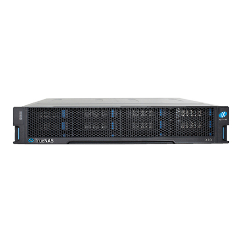
Drive trays are used to mount drives in the array. Drive trays are installed in drive bays in the chassis. Each drive bay in the
chassis has two indicator LEDs to the right of the tray. The status LED is blue when the drive is active, and the fault LED is
red if a fault has occurred.
Press the silver button on the drive tray to open the latch. Carefully slide the tray into a drive bay until the right side of the
latch touches the metal front edge of the chassis, then gently swing the latch closed until it clicks into place.
Refer to the installation instructions included with expansion shelves for details on connecting them.
Note: Network cables vary by configuration and are not included. Please contact iX Support (page 6) with any questions.
Connect network cables to the Ethernet ports and Out-of-Band (OOB) management port before attempting to power on and
configure the M-Series for the the first time.
Do not plug the power cords into a power outlet yet. Connect a power cord to the back of one power supply. Place the cord
into the plastic clamp and press the tab into the latch to lock it in place. Repeat the process for the second power supply
and cord.
After both power cords have been connected to the M-Series, they can be plugged into power outlets. The system is con-
figured to automatically power on when connected to a power outlet. This design ensures that the M-Series comes back on
when power is restored after a power failure.
The included bezel is not required for operation.
5
