iXsystems TrueNAS M Series User manual

TrueNAS®M-Series Unified Storage Array
Basic Setup Guide
Version 1.4

Copyright © 2019 iXsystems, Inc. All rights reserved. All trademarks are the property of their respective owners.
The TrueNAS®M-Series Unified Storage Array is a 4U, 24-bay, hybrid data storage array.
TrueNAS®units are carefully packed and shipped with trusted carriers to arrive in perfect condition. If there is
any shipping damage or any parts are missing, please take photos and contact iXsystems support immediately at
[email protected]or 855-GREP4-iX (855-473-7449) or 408-943-4100.
Please locate and record the hardware serial numbers on the back of each chassis for quick reference.
Components: M-Series Unified Storage Array (#1), rackmount rails (#2), bezel (#3), up to 24 drive trays or blank fillers
(#4), two IEC C13 to NEMA 5-15P power cords, two IEC C14 to C13 cords, velcro cable ties (#5), DB9 to 3.5mm serial
cable (#6), hardware (#7).

Front panel indicators: power (#1), locate ID (#2), fault (#3), network activity (#4).
The fault indicator is on during the initial power-on self-test (POST) and off during normal operation. It turns on
if the TrueNAS®software issues an alert. See the Alert section in the Additional Options chapter of the TrueNAS®
User Guide (https://www.ixsystems.com/documentation/truenas).
The M-Series includes one or two TrueNAS controllers in an over-and-under configuration.
Redundant power supplies (#1), serial port (#2), 1Gb Ethernet Out of Band management port (must be connected
to a network for IPMI remote management) and USB 2.0 ports (#3), USB 3.0 ports (#4), 10GB Ethernet ports (#5),
VGA monitor port (#6), ID indicator (#7), HD Mini SAS3 connectors (#8), networking ports (#9), asterisk slot for Fi-
bre Channel or additional networking (#10), TrueNAS controller management port (#11), TrueNAS controller serial
number (#12).

Redundant power supplies (#1), serial port (#2), 1Gb Ethernet Out of Band management port (must be connected
to a network for IPMI remote management) and USB 3.0 ports (#3), USB 2.0 ports (#4), 10GB Ethernet ports (#5),
VGA monitor port (#6), ID indicator (#7), HD Mini SAS3 connectors (#8), networking ports (#9), asterisk slot for Fi-
bre Channel or additional networking (#10), TrueNAS controller management port (#11), TrueNAS controller serial
number (#12), NVMe activity indicators (#13).

Extend the inner rack rail until it locks in place (1). Slide out the cabinet rail until it stops (2).
Remove the cabinet rail by sliding the white release tab away from the inner rack rail (3), then pull the cabinet rail
free (4).
The cabinet rails are mounted on both sides of the system cabinet. Align the cabinet rail keyholes with the three
posts (ES24) or four posts (M-Series) on the side of the chassis and slide the rail until the post is secured in the
keyhole slot of the rail.
Align the rail hole with the screw hole and secure the rail with one M4x4L screw. Repeat this process to mount
and secure the second cabinet rail on the other side.

A TrueNAS®M-Series or ES24 requires 4U of vertical rack space. The rack rails are installed in the bottom 2U of
the total 4U height.
The inner rack rail must be unlocked and retracted before installing the rail in the rack. Rotate the release lever on
the back of the inner rail clockwise as shown on the arrow label (1). Push the inner rail toward the back of the rail
assembly until it stops (2).
Place the rail in the rack with the front end toward the front of the rack, aligning the pins with the mounting holes
in the front of the rack. Push the pins into the holes until the latch clicks.
At the rear end of the rail, align the pins with the rack holes, making sure the rail is level. Swing the gray latch han-
dle outward (1) and pull it to extend the rail rearwards until the rail pins are fully seated in the rack holes (2). Re-
lease the latch to allow it to lock into place. Repeat the process for the second rack rail.

Caution: Two people are required to safely lift the chassis for rack installation or removal. Do not install
drives until after the chassis has been installed in the rack, and remove all drives before removing the chassis
from the rack.
Extend both inner rack rails outward from the rack until they lock in place. Align the cabinet rails with the inner
rack rails and slide them into the rack rails until they are fully seated.
When both cabinet rails are secured in the rack rails, gently push the chassis until it stops halfway in. Slide the
blue release tabs on both cabinet rails toward the front of the system (1) while pushing the unit into the rack.
Push the chassis into the rack until it is flush with the front of the rack (2).
Anchor the unit in the rack on both sides with long M5 screws. On the M-Series, the screw hole is behind a small
door on each ear.

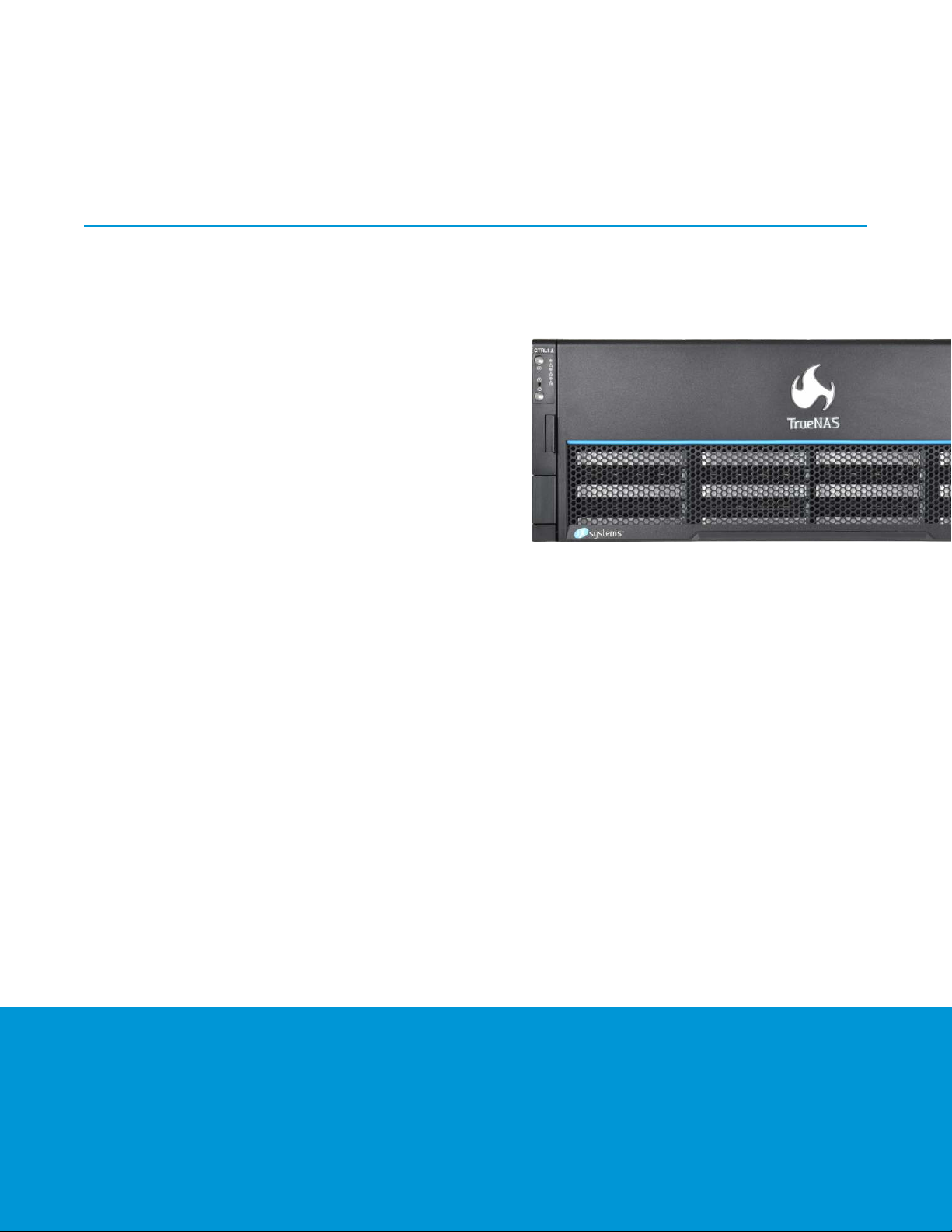
Drives are mounted in drive trays, which are then installed in drive bays in the ES24 or M-Series chassis.
Each drive bay in the chassis has two indicator lights to the right of the tray. The upper light is blue when the drive
is active. The lower light is solid red if a fault has occurred. Both lights blink to identify drives that are hot spares.
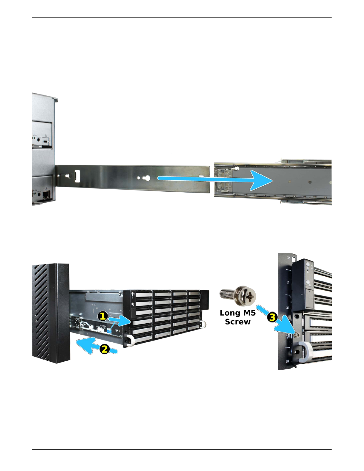
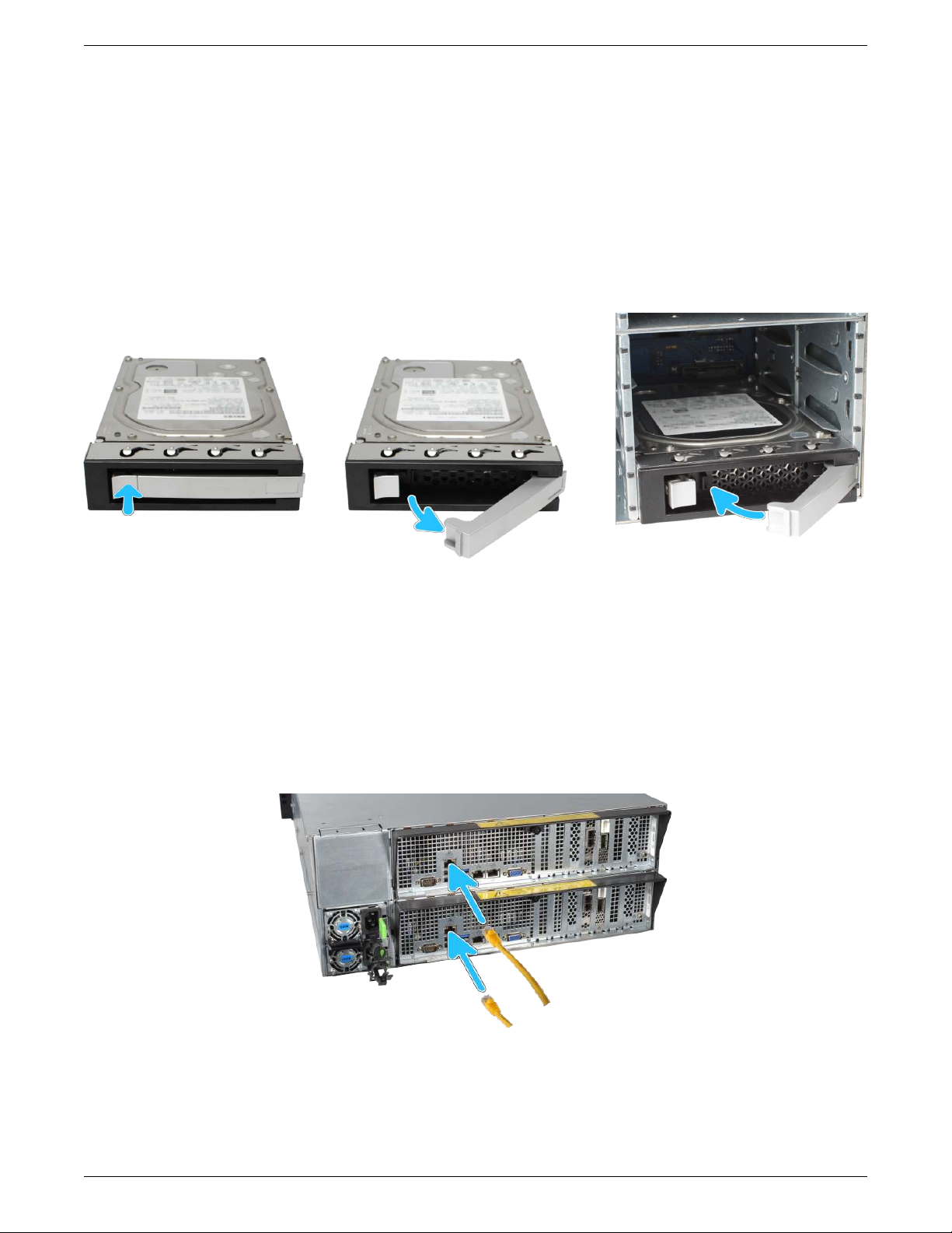
Press the silver button on the drive tray to open the latch. Carefully slide the tray into a drive bay until the right
side of the latch touches the metal front edge of the chassis, then gently swing the latch closed until it clicks into
place.
All drive bays must be filled to maintain proper airflow for cooling. If fewer than 24 drives are connected, filler
blanks must be placed in the empty bays.
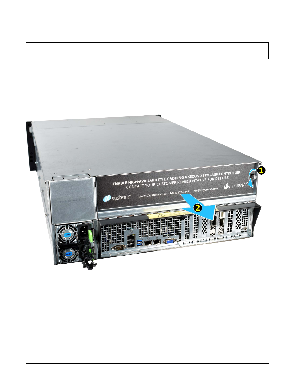
Refer to the installation instructions included with expansion shelves for details on connections.
Connect network cables before powering on the M-Series. Cable specifications and requirements vary by configu-
ration, so they are not included with the system.
Connect network cables from the local switch or management network to the Out-of-Band (OOB) IPMI manage-
ment port on each TrueNAS controller.
Network ports are preconfigured to customer specifications before shipment. Contact iX Support (page 13) for de-
tails on connecting them to the local network.

Do not plug the power cords into a power outlet yet. Connect a power cord to the back of one power supply.
Place the cord into the plastic clamp and press the tab into the latch to lock it in place. Repeat the process for the
second power supply and cord.
After both power cords have been connected to the M-Series, they can be plugged into power outlets. The system
is configured to automatically power on when connected to a power outlet. This design ensures that the M-Series
comes back on when power is restored after a power failure.
The included bezel is not required for operation. To attach the bezel, slide the right side of the bezel into the at-
tachment points on the right ear. Push the left side of the bezel into the left ear latch until it locks into place.
To remove the bezel, push the left ear release tab away from the bezel to release. Swing the bezel out to remove.

Warning: To avoid data loss in an NVDIMM SLOG, TrueNAS controllers must be properly shut down and
powered off before they are removed from the chassis.
Touch the chassis metal top or sides before beginning work. Observe proper antistatic procedures when working
with TrueNAS controllers or other electronic components.
M-Series systems with only one TrueNAS controller have an internal shipping brace that must be removed before
adding a second TrueNAS controller.
Remove the cover plate thumbscrew (1) and controller slot cover (2).

Unscrew the retention screw (1) and remove the brace (2) from the M-Series chassis. Replace the retention screw
(1).
Confirm there are no obstructions in the TrueNAS controller slot, then continue with the TrueNAS controller instal-
lation in the next section.

Use both hands to lift and carry the TrueNAS controller from the bottom only.
Insert the TrueNAS controller into the chassis. Press only on the bottom, sides, or handle of the TrueNAS con-
troller, sliding it into the chassis until it stops (1). Lift the black release handle to lock the TrueNAS controller into
place (2). Tighten the thumbscrew to lock the handle.

Unlock the TrueNAS controller handle by turning the thumbscrew counterclockwise until it releases the handle
(1). Do not pull or press on any portion of the TrueNAS controller except the black release handle. Pull the
black release handle down (2) to release the TrueNAS controller.
Use both hands to grasp the TrueNAS controller only by the sides, bottom, or handle. Slide the TrueNAS con-
troller out (3).

The console displays the IP address of the TrueNAS®M-Series graphical web interface, 192.168.100.231 in this ex-
ample:
Thewebuserinterfaceisat:http://192.168.100.231Enter the IP address into a browser on a computer on the same network to access the web user interface.
The TrueNAS®User Guide has complete software configuration and usage instructions. It is available by clicking
Guide in the TrueNAS®web interface or going directly to https://www.ixsystems.com/documentation/truenas/.
For assistance, please contact iX Support:
Contact Method Contact Options
Web https://support.ixsystems.com
Email [email protected]Telephone Monday - Friday, 6:00AM to 6:00PM Pacific Standard Time:
• US-only toll-free: 855-473-7449 option 2
• Local and international: 408-943-4100 option 2
Telephone After Hours (24x7 Gold Level Support only):
• US-only toll-free: 855-499-5131
• International: 408-878-3140 (international calling rates will
apply)
Other manuals for TrueNAS M Series
2
Table of contents
Other iXsystems Storage manuals

iXsystems
iXsystems TrueNAS R Series Manual

iXsystems
iXsystems TrueNAS M Series Manual

iXsystems
iXsystems TrueNAS F Series User manual

iXsystems
iXsystems FreeNAS Mini Manual

iXsystems
iXsystems FreeNAS Mini User manual

iXsystems
iXsystems TrueNAS Mini Series Manual

iXsystems
iXsystems TrueNAS R50 Manual

iXsystems
iXsystems TrueNAS ES24 Manual

iXsystems
iXsystems TrueNAS F Series User manual

iXsystems
iXsystems TrueNAS X Series Manual