manuals.online logo
Brands
  1. Home
  2. •
  3. Brands
  4. •
  5. jablotron
  6. •
  7. Security Sensor
  8. •
  9. jablotron JA-160PC User manual

jablotron JA-160PC User manual

JABLOTRON ALARMS a.s.
Pod Skalkou 4567/33 46601 Jablonec n. Nisou
Czech Republic www.jablotron.com
||
|
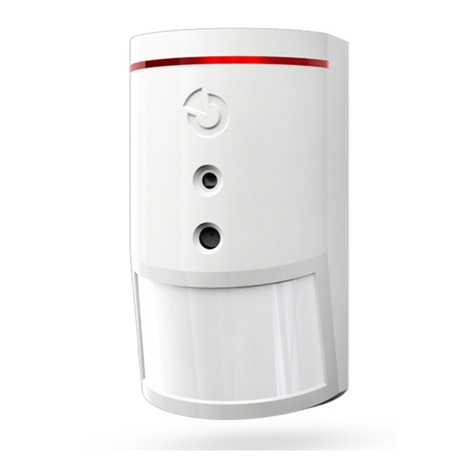
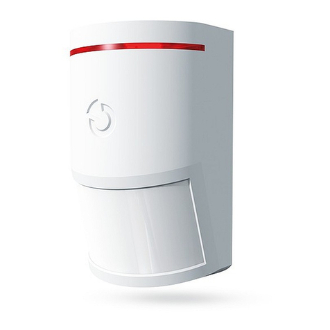
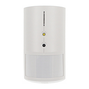
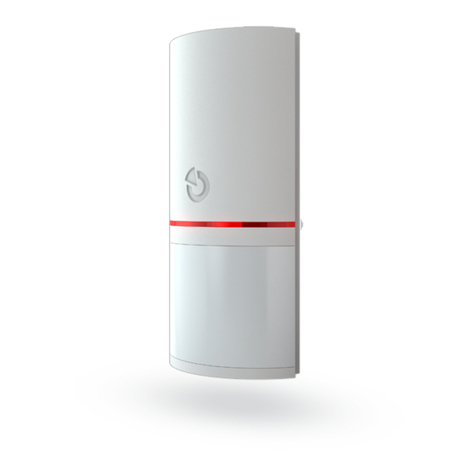
JA-160PC (90) PIR motion BUS detector with a 90° verification camera
JA-160PC (90) PIR motion BUS detector with a 90° verification camera 1 / 3 MMQ53102
This device is a wireless component of the JABLOTRON JA-100
system. It serves for the detection of human movement in building
interiors and visual alarm confirmation. The camera takes colour photos
with a resolution of up to 640x480 pixels. Photos are taken following
detected movement, which ensures that the cause of the alarm
is always recorded. The camera is equipped with a visible flash for
taking photos in the dark. The images are saved in the internal memory
of the detector and then they are forwarded to the control panel
via radio signal and from the control panel they can be sent
to MyJABLOTRON, ARC and users. The detector can also take a photo
by request. The detector should be installed by a trained technician with
a valid certificate issued by an authorised distributor.
Installation
The detector can be installed on
the wall or in the corner of a room. There
should be no objects which quickly
change temperature (e.g. heating
appliances) or which move (e.g. curtains
hanging above a radiator, robotic vacuum
cleaners) or pets in the detector’s field
of sight. It is not recommended installing
the detector opposite windows
or in places with intense air circulation
(close to ventilators, heat sources,
air conditioning outlets, unsealed doors,
etc.). There should be no obstacles
in front of the detector which might
obstruct its view of the protected area.
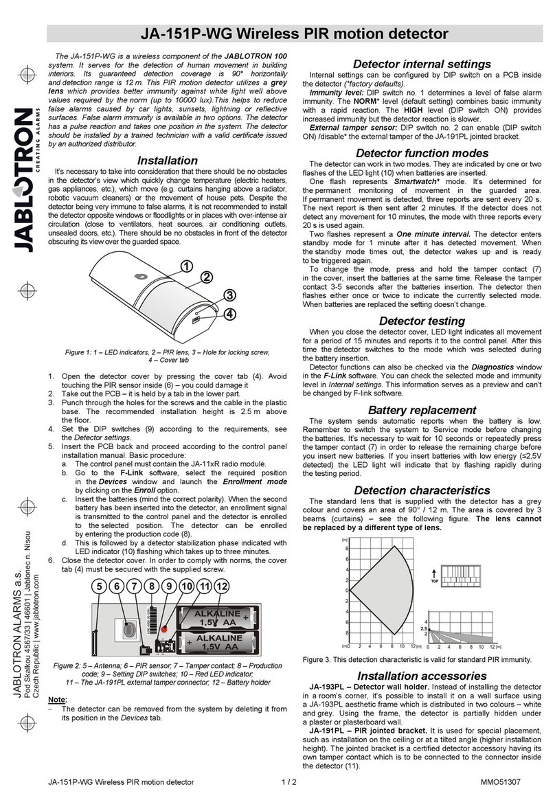
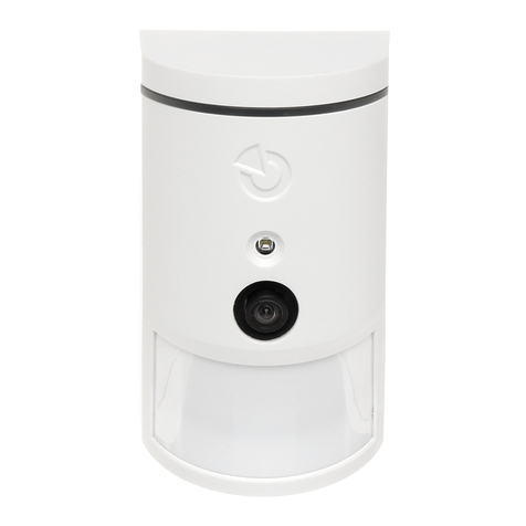
Figure: 1 – flash for illumination; 2 – camera lens;
3 – PIR detector lens; 4 – cover tab;
Avoid installation too close to a ceiling.
Using flash may cause over-exposure
of the scene due to reflections.
1. Open the detector cover (by pushing the cover tab (4)).
Avoid touching the PIR sensor inside (15) – you could damage it.
2. Take out the PCB – it is held by a tab (9).
3. The recommended installation height is 2.5 m above the floor.
4. Attach the plastic base to the wall using screws (vertically,
with the cover tab facing downwards).
5. Re-insert the PCB and plug the connecting cable (6) into
the connector on the PCB.
Figure: 5 – Camera module; 6 – connection cable; 7 – batteries; 8 – red LED
indicator; 9 – PCB tab; 10 – yellow LED; 11 – yellow LED indicator of Micro
SD card; 12 – Micro SD memory card; 13 – mini USB connector;
14 – tamper contact; 15 – PIR sensor; 16 – production code.
6. Proceed according to the control panel installation manual.
Basic procedure:
a. The control panel must contain already enrolled JA-11xR radio
module.
b. Go to the F-Link software, select the required position
in the Devices tab and launch the enrolment mode by clicking
on the Enroll option.
c. Insert the batteries (mind the correct polarity). When the second
battery has been inserted into the detector, an enrollment signal
is transmitted to the control panel and the detector is enrolled
to the selected position. This is followed by up to three minutes
detector stabilization phase indicated by the illuminated red LED
indicator. If discharged batteries have been inserted the red LED
indicator flashes for 3 minutes.
d. If the detector is enrolled as the first PIR camera or the control
panel is not connected to an external mass storage, F-Link
shows a dialogue window with the question: “Enable image
transfer to external storage?” We recommend enabling this
option with the agreement of the customer and confirming this
acceptance by recording it in the system service log with his
signature.
Note: If the transmission is not enabled, images will be saved in the
internal memory of the detector and the control panel only. Then
it is impossible to send them to users’ cell phones and e-mails.
7. Close the detector cover and test its functionality. When
the detector has been closed, it starts the 15 minute test mode
during which it indicates and reports every movement. After that,
the red LED will not indicate movement and the detector works
in the standard mode.
Notes:
-When the control panel is in service mode, the detector indicates
every movement with the red LED indicator.
-If you want to enroll the detector in the control panel after the battery
has already been inserted, remove the battery first and then press
and release the tamper contact (14) to discharge the rest of the
energy and then enroll the detector.
-The detector can be enrolled by entering the production code (16)
in the F-Link software (or a bar code reader). Enter all digits located
below the bar code (1400-00-0000-0001).
-If you want to remove the detector from the system, erase it from its
position in the control panel.
-In order to comply with the EN 50131-2-4 norm, the cover tab (4)
must be secured with the supplied screw.
Detector internal settings
Settings can be set by F-Link software in the Devices tab. Use the
Internal settings option on the detector’s position to open a dialog
window where you can configure the settings (*default settings):
PIR immunity level: Defines false alarm immunity. The *Standard level
combines basic immunity with a rapid reaction. The Increased level provides
higher immunity but the detector reaction is slower.
LQ photo quality: Standard* quality uses optimized compression in order
to achieve the fastest possible transfer to the ARC or to the end user
in MyJABLOTRON. The goal is achieving alarm verification in the fastest
time possible. If the quality is switched to Extended, the system will use
lower image compression which will at least double the time necessary
to transfer the image (depends on the conditions of the captured scene).
Change the quality only if the LQ image does not have the quality required
by the customer – it may depend on the captured space. It is not
recommended when there are more verification detectors in the premises
which may take images at the same time.
Taking photos during alarms: No flash, *With flash
Flash intensity: Low, *Medium, High – if the captured scene is over-
exposed (e.g.in a small room), the intensity of the flash can be decreased.
It can be increased for larger spaces.
Lithium battery operation: If the detector is tasked with frequent
operation (e.g. frequently requested photos by MyJABLOTRON) and
is configured to high flash intensity, we recommend the use of AA 1.5 V
lithium batteries. If you operate the detector from lithium batteries,
this parameter must be enabled (it adjusts detection of low batteries).
PG output reaction: You can select PG outputs, whose activation will
trigger taking a picture (*No, camera does not react to PG). For further info
see Installation recommendations, cautions.
Taking a photo by PG activation: No flash, *With flash
Taking photos during entrance delay: *No flash, With flash
Send pre-alarm photos: This option is not available when the Extended
LQ photo quality is selected due to more than double size of the photo and
therefore longer transmission time. When this parameter is enabled the
detector will send photos even when the detector is configured with repeated
or confirmed reaction and the alarm has not been confirmed. During every
entrance delay, up to two photos can be taken when the detector is triggered
even when the system has been unset properly.
This option will noticeably increase the volume of data transferred
to MyJABLOTRON or external mass storage. If the system is unset (alarm is
triggered), the images taken during the entrance delay will be sent
automatically regardless this option
Test: takes a test photo (LQ) with a flash and F-Link displays it. When the
Detail button is pressed, the F-Link software shows the picture in a 640x480
px resolution. Photos are sent to the external mass storage (provided that
transferring is enabled).
To set the JA-160PC (90) detector to comply
with security grade 2 or other requirements use
F-Link SW, Parameters tab and the option
“System profiles”.
Camera and basic reactions
The process of how the camera takes pictures depends
on the settings in the F-Link software – the Devices tab. Choose a type
of Reaction on the detector’s position.
JA-160PC (90) PIR motion BUS detector with a 90° verification camera
JA-160PC (90) PIR motion BUS detector with a 90° verification camera 2 / 3 MMQ53102
Instant: During an alarm triggered by the detector, the camera can be
activated up to 3 times (then it will be auto-bypassed). Each activation,
depending on the detected movement, takes 2 photos maximum. Photos
are sent to the control panel (6 photos maximum).
Delayed: The first activation (entrance delay) takes up to 2 photos
according to the detected movement and saves them into the internal
memory (Send pre-alarm image disabled). When alarm is triggered, photos
are sent from the internal memory to the control panel. Then the behaviour
is the same as with an instant reaction (8 photos maximum).
Warning: When the Device autobypass / 3rd alarm is enabled
(located in Settings/Parameters), then taking photos is blocked after
the 3rd alarm. During each alarm the detector can be triggered
up to three times. This way, the number of taken and transferred photos
can be tripled (18/24 photos). Applies to Instant/Delayed reactions.
Installation recommendations, cautions
Several JA-160PC (90)s can be installed in the system. However,
triggering several detectors at the same time will extend the transmission
time of photos to the control panel and to the external storage.
Complete transmission can take a few minutes.
Installation in the corner of a room requires more attention during
testing due to possible reflection of flash in the photographed scene
(especially in the dark).
In order to take a photo using a PG output, use the F-Link software
and set the Impulse parameter in the PG outputs/Function menu
to a time of at least 1 min. The PIR is limited to taking 1 requested
photo by PG status per minute.
The number of pre-alarm photos taken by a PG output is limited
to 40 photos/day/control panel. The photo counter is reset at 00:00 hrs.
Alarm photos and photos requested in MyJABLOTRON have no limitation.
When you start transferring the pictures to MyJABLOTRON
or external mass storage, it’s necessary to take into account the cost
of data transfer to be paid to your GSM provider.
Detection characteristics
PIR detector has a 90°/12 m coverage – see picture below.
The detection characteristics of the PIR part has no influence
on the camera part of the detector.
Warning:
- The lens cannot be changed for other types.
- The camera has a viewing angle of 90°, the camera flash has
a range of 3 m.
Saving and browsing the pictures
Every photo is taken twice: the first in low resolution (LQ = 320x240
pixels), the second with high resolution (HQ = 640x480 pixels).
All of the exposures are saved into the independent folders Foto_LQ
and Foto_HQ on the Micro SD card. When the card’s capacity is full, the
oldest photos will be replaced by new ones. Photos saved on the micro SD
card can be browsed in a photo browser on a PC.
Note: Some antivirus software may write their own data on the Micro SD
card. The detector will automatically format the SD card marked this way.
SD card formatting erases all data which has been saved. For more
information about formatting see Formatting the Micro SD card.
Photos are sent to the control panel in LQ. You can browse through these
images in F-Link and J-Link software event memory by clicking
on an event called New image. Photos are displayed in LQ, if you click
on Detail you can get second-exposure pictures (HQ). Images can be
searched and browsed by a file manager or picture browser. In order
to display the photos this way it is necessary to start F-Link (J-link)
software, be logged into the control panel as a service technician
or Administrator and then load the control panel memory.
Disc: Flexi_log /Foto. Here are all the photos which have been sent to the
control panel (LQ) and photos which have been requested in Detail (HQ).
Picture transmission from the control
panel
It’s necessary to choose one of these options in order to send photos
to the user:
Transfer photos to MyJABLOTRON
When the SIM card supplied by a device manufacturer (distributor)
is used and the customer uses MyJABLOTRON services, then the
customer has direct access to the photos from this service. Parameter
settings of the transfer of pictures are done during the panel
registration. All the photos are delivered and visible in MyJABLOTRON.
Every single photo can be requested in HQ resolution. There you can
also choose telephone numbers (for SMS) or e-mail addresses which
will receive a message when a new picture is taken. MyJABLOTRON
can request a new picture without PG output activation (see Installation
recommendations, cautions).
MyJABLOTRON respects permissions of individual users concerning
photo verification accordingly to sections to which the users have
access (for example, a user from section 1 cannot browse through
photos from section 2)
Transferring pictures to external mass storage
If MyJABLOTRON is not available, photos can be transferred to external
mass storage http://img.jablotron.com. Communication parameters are
preset in the factory and are activated when the first PIR detector with
a camera is enrolled to the system and after agreeing with transfers.
When communication works properly the user must create an account
at http://img.jablotron.com by entering the login and password, and then
filling in the registration code of the control panel which will make
photos immediately available for browsing. The registration code
is on the control panel PCB or you can read it via F-Link software,
Communication tab, Registration code field.
Reports of new photos stored in this mass storage can be sent
to an e-mail.
Note: If there are more detectors in the premises, all photos will be
visible to all people with access to the created premises regardless
of the sections assigned to them.
Photos stored at http://img.jablotron.com are available only in LQ
quality. Photos in HQ quality cannot be requested.
In both cases sending reports straight from the control panel will
normally work. When the picture is saved at MyJABLOTRON
or http://img.jablotron.com, the control panel will send an SMS report
to all users depending on the settings in F-Link,User reports tab,
Alarm photo settings. Sent SMSes include an http link to display the
photo. The photos can also be browsed on mobile phones with
a connection to the internet.
Warning:
- This detector allows you to take photos by PG output reaction
or from MyJABLOTRON even when the system is unset.
The producer strictly warns the user that the detector has to
be used within the limits given by particular laws or norms,
especially laws about the protection of personal privacy.
- The use of the detector is also subject to regulations
on the protection of personal data and the manufacturer
recommends that users be aware of the obligations applicable
to the operation of CCTV.
- According to these regulations users have an obligation to ensure
the approval of persons in range of the detector during
the acquisition of video recordings or the obligation to indicate
the image capture area by information tables.
Formatting the Micro SD card
The detector is supplied with a formatted Micro SD card (12). The yellow
indication LED (11) is turned off in normal detector mode. Slow LED flashing
indicates that the card was removed while data was being written on it,
or it has been changed for another SD card. The detector will work
normally with a new SD card only if the detector performs a card formatting.
Formatting is started by pressing the tamper contact (14). The formatting
procedure is indicated by quick flashing of the yellow LED indicator (11).
During this process all photos on the SD card will be erased, however,
a back-up of the photos is in the event memory log, alternatively
in external storage.
Changing the batteries
The detector monitors its own batteries and when they are depleted,
it will inform you about this with a brief flash of the LED indicator when
the detector is triggered. This information is also delivered to the control
panel. We recommend changing the batteries within two weeks from the
moment the low battery indication starts. After replacing the batteries,
the detector sensor needs up to 3 minutes to stabilize (the red LED
indicator is lit up). The batteries should be replaced by a service
technician with the control panel in Service mode. Always replace both
Top viewSide view
JABLOTRON ALARMS a.s.
Pod Skalkou 4567/33 46601 Jablonec n. Nisou
Czech Republic www.jablotron.com
||
|
JA-160PC (90) PIR motion BUS detector with a 90° verification camera
JA-160PC (90) PIR motion BUS detector with a 90° verification camera 3 / 3 MMQ53102
batteries for new ones. Do not throw the batteries in the trash.
Deliver them to a civic amenity site instead.
FW upgrade
1. Remove at least one battery from the detector.
2. Run the F-Link software. Connect the USB cable with the mini USB
connector (13) inside the detector and then put back the battery
(or batteries) back.
3. Boot mode is indicated by the lit up red LED indicator and by short
flashing of the yellow LED.
4. Then continue the same way as if you were to upgrade the control
panel: Control panel ĺupgrade Firmware ĺFKRRVH WKH):SDFNILOH
ĺ LQ WKH ZLQGRZ ZKHUH \RX ZLOO EH RIIHUHG D GHYLFH WR XSJUDGH VHOHFW
the USB option and type of the device.
Technical specifications
Power 2x alkaline battery type LR6 (AA) 1.5 V
(alternatively 2x AA lithium battery, 1.5 V)
Typical lifetime about 2 years (1 activation and 1 series of photos a day)
Please note: Batteries are not included
Low battery voltage
- Alkaline batteries 2,52 V
- Lithium batteries 2,62 V
Recommended installation height 2.5 m above the floor
PIR Detection angle / detection coverage: 90°/12 m
Horizontal camera capture angle 90°
Range of the flash max. 3 meters
Resolution of the camera LQ 320x240; HQ 640x480 pixels
Photo size LQ/HQ (typically) 2-20 kB / 2-64 kB (6 kB / 35 kB)
Typical (LQ) photo transmission time to the control panel (ideally)
up to 20 sec. (10 sec.)
Typical (HQ) photo transmission time to the control panel (ideally)
up to 130 sec. (60 sec.)
Typical photo transfer time to the server 15 s/GPRS; 2 s /LAN
Dimensions, weight 110 x 60 x 55 mm, 102 g
Classification Security grade 2/Environmental class II
-according to EN 50131-1, EN 50131-2-2, EN 50131-5-3
- operational temperature range -10 to +40 °C
- operational environment indoor general
- certification body Trezor Test s.r.o. (no. 3025)
Also complies with ETSI EN 300 220, EN 50130-4,
EN 55022, EN 60950-1
Can be operated according to ERC REC 70-03
JABLOTRON ALARMS a.s. hereby declares that the JA-160PC
(90) is in a compliance with the relevant Union harmonisation
legislation: Directives No: 2014/53/EU, 2014/35/EU, 2014/30/EU,
2011/65/EU. The original of the conformity assessment can
be found at www.jablotron.com - Section Downloads.
Note: Although this product does not contain any harmful
materials we suggest you return the product to the dealer
or directly to the producer after use.

Other jablotron Security Sensor manuals

jablotron JA-111TH User manual

jablotron

jablotron JA-111TH User manual

jablotron JK-16 PROFI User manual

jablotron

jablotron JK-16 PROFI User manual

jablotron JA-120PC User manual

jablotron

jablotron JA-120PC User manual

jablotron JA-151P-WW User manual

jablotron

jablotron JA-151P-WW User manual

jablotron JA-187P User manual

jablotron

jablotron JA-187P User manual

jablotron JA-158P User manual

jablotron

jablotron JA-158P User manual

jablotron JA-80S User manual

jablotron

jablotron JA-80S User manual

jablotron JA-85B User manual

jablotron

jablotron JA-85B User manual

jablotron JA-160PC User manual

jablotron

jablotron JA-160PC User manual

jablotron JA-60V User manual

jablotron

jablotron JA-60V User manual

jablotron Ei208W User manual

jablotron

jablotron Ei208W User manual

jablotron JA-160PC User manual

jablotron

jablotron JA-160PC User manual

jablotron JA-88P User manual

jablotron

jablotron JA-88P User manual

jablotron JA-150P User manual

jablotron

jablotron JA-150P User manual

jablotron LARGO JS-20 User manual

jablotron

jablotron LARGO JS-20 User manual

jablotron JA-60P User manual

jablotron

jablotron JA-60P User manual

jablotron JA-181M User manual

jablotron

jablotron JA-181M User manual

jablotron JA-84P User manual

jablotron

jablotron JA-84P User manual

jablotron JA-60V User manual

jablotron

jablotron JA-60V User manual

jablotron JA-158P User manual

jablotron

jablotron JA-158P User manual

jablotron JA-120PC User manual

jablotron

jablotron JA-120PC User manual

jablotron JA-160PC User manual

jablotron

jablotron JA-160PC User manual

jablotron JA-150P PET User manual

jablotron

jablotron JA-150P PET User manual

jablotron JA-87P User manual

jablotron

jablotron JA-87P User manual

Popular Security Sensor manuals by other brands

Inficon T-Guard2 Translation of the original operating instructions

Inficon

Inficon T-Guard2 Translation of the original operating instructions

Siemens RAR Series quick start guide

Siemens

Siemens RAR Series quick start guide

Optex RLS-50100V Important product information

Optex

Optex RLS-50100V Important product information

BST KLC 10 technical information

BST

BST KLC 10 technical information

Siemens DF-30 Installation, Application, And Technical Instructions

Siemens

Siemens DF-30 Installation, Application, And Technical Instructions

Schwaiger Secure 4 You HGA400 533 instructions

Schwaiger

Schwaiger Secure 4 You HGA400 533 instructions

Apollo 58000-300APO installation guide

Apollo

Apollo 58000-300APO installation guide

Bosch DS935LSN installation instructions

Bosch

Bosch DS935LSN installation instructions

Honeywell C7061A Product data

Honeywell

Honeywell C7061A Product data

Elko iNELS RF Control RFMD-100 quick start guide

Elko

Elko iNELS RF Control RFMD-100 quick start guide

Electronics Line EL-1484 manual

Electronics Line

Electronics Line EL-1484 manual

Ronin Lift user manual

Ronin

Ronin Lift user manual

BUCKINGHAM MFG SuperSqueeze 488PR Instructions & warnings

BUCKINGHAM MFG

BUCKINGHAM MFG SuperSqueeze 488PR Instructions & warnings

C.P. Electronics MWS6-PRM-LV installation guide

C.P. Electronics

C.P. Electronics MWS6-PRM-LV installation guide

DELTA PLUS METIS manual

DELTA PLUS

DELTA PLUS METIS manual

Abus FU8360 manual

Abus

Abus FU8360 manual

Blackline Safety G7 BRIDGE Technical  user's manual

Blackline Safety

Blackline Safety G7 BRIDGE Technical user's manual

Tinker & Rasor AP/W instructions

Tinker & Rasor

Tinker & Rasor AP/W instructions

manuals.online logo
manuals.online logoBrands
  • About & Mission
  • Contact us
  • Privacy Policy
  • Terms and Conditions

Copyright 2025 Manuals.Online. All Rights Reserved.