manuals.online logo
Brands
  1. Home
  2. •
  3. Brands
  4. •
  5. jablotron
  6. •
  7. Security Sensor
  8. •
  9. jablotron JA-80PB User manual

jablotron JA-80PB User manual

The JA-80PB wireless motion/glass-break detector MHP52504
1
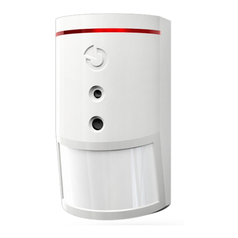
The JA-80PB wireless PIR motion/glass-break detector
The JA-80PB is a component of Jablotron’s Oasis 80 alarm system. It consists
of two independent detectors which occupy two separate enrollment
addresses in the control panel. The motion detector uses a PIR sensor. The
glass-break detector uses the analysis of air pressure variations combined with
the characteristic sound of glass breaking. The product is designed for internal
use in buildings. The battery-powered detector communicates via OASIS radio
protocol.
Lithium 3.6 V
PIR movement detector
Lithium
3.6V
Glass-break detector
Installation
Installation shall only be undertaken by technicians holding a certificate issued
by an authorized distributor. The detector can be installed on a flat wall or in
the corner of a room. Within the detection range of the PIR sensor avoid the
presence of objects rapidly changing in temperature, such as electrical
heaters, gas appliances etc. Moving objects with a temperature close to that of
humans such as curtains moving above a radiator, and pets should also be
avoided. Detectors should not face windows or spotlights or be near fast-
moving air e.g. near ventilation fans or open windows or doors. Because of its
sensitivity to air pressure changes and sounds it should not be located close to
air conditioning or ventilation outlets. There should be no sources of vibration
or audible sounds in the protected area. There should also be no obstacles
blocking the detector’s “view” of the protected area. Keep the detector away
from metal objects which could interfere with radio communication.
Warning: The most frequent cause of false alarms is bad detector-positioning
Do not arm this detector if there are any people or pets moving within the
protected area.
1. Open the detector cover by pressing the tab and disconnect the cable to
the module located in the front cover.
2. Remove the internal PIR module held by an internal tab.
3. Punch screw holes through the rear plastic cover. At least one screw
should penetrate the tamper-sensitive section.
4. Screw the rear cover to the wall, about 2 metres above the floor
(vertically, with the tab down).
5. Return the PIR module to its original place.
6. Leave the battery disconnected and the cover open and then follow
the control panel or receiver manual. The basics of enrollment are:
a. Enter enrollment mode on the control panel by keying in “1” in
Service mode.
b. Install a battery in the PIR detector to activate its enrollment.
c. Install a battery in the glass-break detector and then connect its
cable to the PIR module. This will activate its enrollment to the
next vacant address in the control panel. This means that the
glass-break detector enrolls after the PIR does.
d. Exit enrollment mode by pressing “#”
To observe EN 50131-2-2 the tab must be secured by the supplied screw.
To enroll a detector after having already connected batteries, first disconnect
the batteries, and press and release the tamper sensor to discharge any
remaining charge to ready the device for enrollment. After installing batteries
into the detector, allow two minutes for stabilisation. During this period the LED
is continuously lit.
PIR module DIP switches
NORM / HIGH: selection of immunity to false alarms. The NORM position
combines very good immunity with fast sensor reactions. The HIGH position
gives increased immunity with a slower reaction time and is only used for
problematic installations.
INS / DEL. DEL provides entrance & exit delays for detectors installed in a
building entrance. INS allows the detector to instantly trigger alarm activation
if the control panel is armed. This DIP switch (INS/DEL) only has an effect if
the detector has a natural reaction assigned to its address in the Oasis
control panel. It also has no effect when used with a UC-8x or AC-8x receiver.
Glass-break module DIP switches
DEL / INS selects the reaction of the control panel if glass-breaking is
detected. DEL provides entrance & exit delays and is recommended for
detectors installed near a building’s entrance door. INS allows the detector to
instantly trigger alarm activation if the control panel is armed. This DIP switch
(INS/DEL) only has an effect if the detector has a natural reaction assigned to
its address in the Oasis control panel. It also has no effect when used with a
UC-8x or AC-8x receiver.
PIR / GBS: This selects whether PIR or glass-break triggering is shown by the
LED. Changing this setting only has an effect during the first 15 minutes after
closing the cover (test mode).
Note: Although both detectors are located in one housing, they do act
independently. Each one has its own address. Each one also has its own
selectable reaction via DIP switches in the detector or in SERVICE mode on
the control panel.
Testing the detector
15 minutes after closing the detector cover, the LED shows PIR or glass-beak
detector triggering according to what was previously selected by the PIR/GBS DIP
switch during test mode. The strength and quality of detector signals can be
measured by the control panel in Service mode.
With the DIP switch in position PIR, short LED flashes indicate the processing of
movement triggering the detector. Long flashes show that movement detection is
being signalled to the control panel.
With the DIP switch in position GBS, the LED flashes very briefly when air
pressure changes occur, e.g. a soft knock on a window. A long flash indicates
triggering by breaking glass and the transmission of a signal to the control panel.
Testing and adjusting the glass-break sensor:
• Using a suitable tool or a hand protected by gloves, one by one, knock all
the windows that should be under the detector’s protection. A visible
deformation of the glass should occur but without any damage.
• The deformation of glass causes a change in the air pressure of the room
which makes the LED on the detector flash quickly. The DIP switch must
be in the GBS position.
• Sensitivity to air pressure changes can be adjusted by a potentiometer on
the glass-break sensor PCB located inside the front cover of the detector.
Turning clockwise increases sensitivity. Avoid selecting too high a
sensitivity as this can cause a short battery lifetime.
• The complete function of the glass-break detector can be tested with a
GBT-212 glass-break simulator. After knocking the glass, this simulator
will automatically generate the characteristic sound of breaking glass to
create the conditions for detector triggering.
• If there are any devices in the detector’s protected area generating sound
such as air conditioning, heating, fax machines, refrigerators, etc., check
that they are not triggering alarms by emitting sounds like breaking glass.
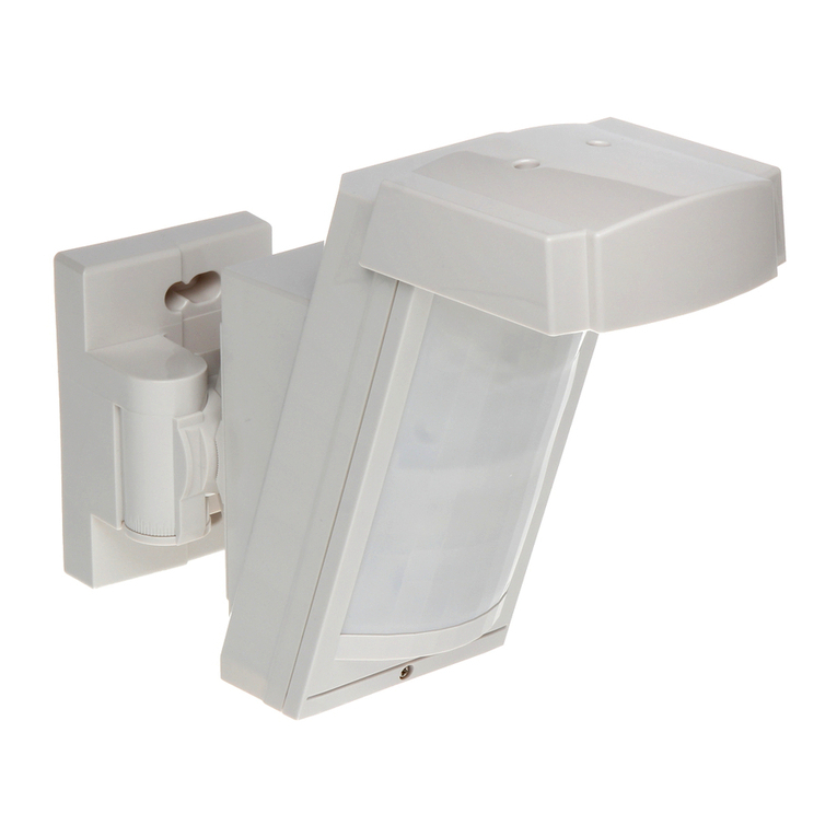
The JA-80PB wireless motion/glass-break detector MHP525042
Detection characteristics of the PIR sensor
The default lens supplied covers an angle of 120° and a distance of 12
metres. The area is covered by three beams as shown in the following
picture.
Top view
Side view
The characteristics can be changed by using optional lenses:
JS-7904 Suitable for long corridors. The middle beam covers 20
meters.
JS-7906 Only employs an upper beam with a 120° angle and a 12
metre range. Ignoring the floor eliminates the effect of the
movement of small pets.
JS-7901 Has a vertical beam forming a wall-like detection barrier
which triggers the detector if someone walks through it.
Note: After changing the lens, test that the desired area is protected.
Incorrect installation of the lens can disable detection.
5 minute/1 minute PIR sensor sleep time
To save battery energy, the PIR sensor part of the detector switches to
battery-save mode 15 minutes after the cover is closed. During battery-
save mode the PIR sensor still always watches out for movement. The first
movement detected is then signalled to the control panel instantly, and for
the next 5 minutes the PIR sensor ignores any further movement.
After these 5 minutes, the PIR sensor then returns to watching out for
movement until re-triggered. The sleep time can be shortened to 1 minute
by pressing the tamper switch during battery installation. Not pressing the
tamper switch gives a sleep time of 5 minutes. This sleep time has no
effect on the glass-break sensor which is always ready to trigger a
glass-break alarm.
Auxiliary alarm input
There is an input terminal in the
detector which, among other
things, can be used to detect open
doors or windows. Open circuiting
the input has the same effect as
movement in front of the detector
The maximum allowable cable
length to connect a normally-
closed sensor to the terminal is 3
metres. Short circuit these
terminals if the input is not used.
Detection characteristics of the glass-break sensor
The directional response of the glass-break sensor has near spherical
characteristic and it is possible to detect breaking glass up to 9 metres
away as can be seen in the below diagram. The size of glass should be at
least 60 by 60 cm. For smaller sizes the detection range can be shorter.
Only breaking glass forming part of the walls within the protected area can
be detected. All kinds of glass can be protected including windows covered
with unbreakable folio.
Warning: This type of detector is not suited to sensing holes being cut
through glass by glass cutters. For this reason, valuables near
windows should be covered by PIR sensors.
Glass-break detector relative directional sensitivity
Battery replacement
This detector has two batteries inside whose condition is regularly
checked. If any of the batteries has expired, then the user or installer is
informed. The detector continues to work and each movement in front
of the detector is shown by a brief LED flash. The batteries should be
replaced within two weeks by a qualified technician in SERVICE mode.
After battery replacement the detector needs two minutes to stabilise
during which the LED is permanently lit. After battery replacement test
the functioning of both sensors. Expired batteries should not be thrown
into the garbage, but disposed of according to local regulations.
Removing the detector from the system
If a detector is removed, the control panel announces the removal. The
detector has to be deleted from its two addresses in the control panel
before intentional removal.
Technical parameters
Voltage of PIR sensor: Lithium battery type LS(T)14500 (3.6V AA / 2.4Ah)
Voltage of GBS sensor: Lithium battery type LS(T)14250 (3.6V ½ AA / 1.2Ah)
Typical battery lifetime approx. 3 years (PIR sensor sleep time 5 min.)
Communication band: 868 MHz, Oasis protocol
Communication range: approx. 300m (open area)
Recommended installation height: 2 - 2.5 m above floor level
PIR sensor detection angle/detection range: 120° / 12 m (with basic lens)
Glass-break detection range 9m (glass min. 60 x 60cm)
Operational environment according to EN 50131-1 II. Indoor general
Operational temperature range -10 to +40 °C
EN 50131-1, EN 50131-2-2, EN 50131-5-3 classification: grade 2
Dimensions, weight 110 x 60 x 55 mm, 120 g
Complies with ETSI EN 300220, EN 50130-4, EN 55022, EN 60950-1
Can be operated according to ERC REC 70-03
FCC ID VL6JA80PB
JABLOTRON ALARMS a.s. hereby declares that the JA-80PB is in
compliance with the essential requirements and other relevant provisions of
Directive 99/5/EC and complies with part 15 of the FCC rules. Operation is
subject to the following two conditions: 1. This device may not cause harmful
interference, and 2. This device must accept any interference received, including
interference that may cause undesired operation.
CAUTION: Changes or modifications no expressly approved by Jablotron could void
the user´s authority to operate the equipment. The original of the conformity
assessment can be found at www.jablotron.com, Technical Support section
Note: Although this product does not contain any harmful materials we
suggest you return the product to the dealer or directly to the producer
after use.

Other jablotron Security Sensor manuals

jablotron JA-15P User manual

jablotron

jablotron JA-15P User manual

jablotron JA-169P User manual

jablotron

jablotron JA-169P User manual

jablotron JA-120PW User manual

jablotron

jablotron JA-120PW User manual

jablotron JA-84P User manual

jablotron

jablotron JA-84P User manual

jablotron JA-80PB User manual

jablotron

jablotron JA-80PB User manual

jablotron JA-180PB User manual

jablotron

jablotron JA-180PB User manual

jablotron JA-188P User manual

jablotron

jablotron JA-188P User manual

jablotron JA-88P User manual

jablotron

jablotron JA-88P User manual

jablotron JA-150P PET User manual

jablotron

jablotron JA-150P PET User manual

jablotron JA-150P User manual

jablotron

jablotron JA-150P User manual

jablotron JA-157P User manual

jablotron

jablotron JA-157P User manual

jablotron JA-180S User manual

jablotron

jablotron JA-180S User manual

jablotron JA-120PC User manual

jablotron

jablotron JA-120PC User manual

jablotron JA-187P User manual

jablotron

jablotron JA-187P User manual

jablotron JA-151P-WG User manual

jablotron

jablotron JA-151P-WG User manual

jablotron JA-111TH User manual

jablotron

jablotron JA-111TH User manual

jablotron JA-120PC User manual

jablotron

jablotron JA-120PC User manual

jablotron LARGO JS-20 User manual

jablotron

jablotron LARGO JS-20 User manual

jablotron JA-158P User manual

jablotron

jablotron JA-158P User manual

jablotron JA-80S User manual

jablotron

jablotron JA-80S User manual

jablotron JB-EXT-TH-R User manual

jablotron

jablotron JB-EXT-TH-R User manual

jablotron JA-115P User manual

jablotron

jablotron JA-115P User manual

jablotron Ei208W User manual

jablotron

jablotron Ei208W User manual

jablotron JA-158P User manual

jablotron

jablotron JA-158P User manual

Popular Security Sensor manuals by other brands

Berthold LB 4700 operating manual

Berthold

Berthold LB 4700 operating manual

Satel AVD-100 manual

Satel

Satel AVD-100 manual

PCB Piezotronics ICP W138A06/-0015 Installation and operating manual

PCB Piezotronics

PCB Piezotronics ICP W138A06/-0015 Installation and operating manual

2M Technology 2MTHWT-HMD user manual

2M Technology

2M Technology 2MTHWT-HMD user manual

schmersal SMS 3 Mounting and wiring instructions

schmersal

schmersal SMS 3 Mounting and wiring instructions

EMS FCX-100-001 installation guide

EMS

EMS FCX-100-001 installation guide

Ezviz T10 quick start guide

Ezviz

Ezviz T10 quick start guide

Fike 60-1039 Installation and maintenance instructions

Fike

Fike 60-1039 Installation and maintenance instructions

PMT Talos SFD-1000 user guide

PMT

PMT Talos SFD-1000 user guide

GTV CR-1 manual

GTV

GTV CR-1 manual

Caroma CARE ARMREST installation instructions

Caroma

Caroma CARE ARMREST installation instructions

Prosense PPS-RCO Series Quick installation guide

Prosense

Prosense PPS-RCO Series Quick installation guide

C.P. Electronics EBMHS series Product guide

C.P. Electronics

C.P. Electronics EBMHS series Product guide

DELTA PLUS NI175 Tehnical manual

DELTA PLUS

DELTA PLUS NI175 Tehnical manual

Paradox Digigard DG85 installation guide

Paradox

Paradox Digigard DG85 installation guide

C.P. Electronics EBDSPIR-AD installation guide

C.P. Electronics

C.P. Electronics EBDSPIR-AD installation guide

Tinker & Rasor M/2 Product instructions

Tinker & Rasor

Tinker & Rasor M/2 Product instructions

Astral Pool BASIC 37058 installation manual

Astral Pool

Astral Pool BASIC 37058 installation manual

manuals.online logo
manuals.online logoBrands
  • About & Mission
  • Contact us
  • Privacy Policy
  • Terms and Conditions

Copyright 2025 Manuals.Online. All Rights Reserved.