Jack A7 User manual

第1页共 10 页
A7 Operation Manual
1 Installation Instructions
1.1 Product specifications
Product Type A7 Supply Voltage AC 220 ±20%V
Power frequency 50Hz/60Hz Maximum output power 550W
1.2 Port diagram
Plug each connection plug of the machine head into the corresponding socket behind the controller as Figure 1-2-1.18P functional port as
Figure 1-2-2.Well connected, please check whether the plug is firmly inserted.
1.2.1 Name of each port
1.2.2 18P function port corresponding table
12 3 456 7 8 9
Thickness
Detection
Signal
Thickness
Detection
GND
Thickness
Detection
Power supply +5V
// / Low Oil level
detection GND
Switchgroup
GND
Switchgroup
Power supply
+5V
10 11 12 13 14 15 16 17 18
/////LowOil
Detection
signal
Switchgroup-
Fill half a needle
Switchgroup-
backstitch
Switchgroup-
Fill the
needle
· Please read this manual carefully, also with related manual for the machinery before use the controller.
· For installing and operating the controller properly and safely, qualified engineers are required.
· Please stay away from arc welding equipment, in order to avoid electromagnetic interference and malfunction of the
controller.
· Keep room temperature bellow 45°c and above 0°c
· Do not use in humidity below 30% or above 95% or dew and mist places.
· Please turn off the power and unplug the power cord, before install the control box and other components,
· To prevent interference or electric leakage accidents, please make the ground work; the power cord ground wire must
be securely connected to earth by an effective way.
· All parts for the repair provided by the Company or approved before use.
· Please turn off the power and unplug the power cord before any maintenance action. There is dangerous high voltage
control box, you must turn the power off after one minute before opening the control box.
· The symbol in this manual means Safety Precautions, please pay attention to it and strictly follow it, to avoid any
unnecessar
y
dama
g
e.
Safet
y
Instruction
18P function port corresponding The pedals mouth 18P function port
corresponding
Exhaust
encoder port
Stepper
encoder
port
Stepper
power
port

第2页共 10 页
1.2.3 12P function port corresponding table
1.3 Wiring and Grounding
We must prepare the system grounding project, a qualified electrical engineer is requested for the construction. Product is
energized and ready for use; you must ensure that the power outlet the AC input is securely grounded. The grounding wire is
yellow and green lines, it must be connected to the grid and reliable security protection on the ground to ensure safe use, and
prevent abnormal situation.
2 Operation Panel Instructions
2.1 Operation Panel Display Instruction
According to the system working state, the LCD module of operation panel will display the current sewing mode,
parameters, start / end back tacking, and presser foot, needle position, soft start sewing etc. Function mark of the operation
panel is as follows:
123456
Wire cutting
Electromagnet
power supply
+33V
//Loose line
Electromagnet
power supply
+33V
Lifting foot
Electromagnet
power supply
+33V
Clamp line
Electromagnet
power supply
+33V
7 8 9 10 11 12
Wire cutting
electromagnet
signal
//Loose line
Electromagnet
signal
Lifting foot
Electromagnet
signal
Clamp line
Electromagnet
signal
:If it is difficult for inserting plug into socket, please check whether they are matching with each other, or the
inserting direction is correct!
:All power lines, signal lines, ground lines, wiring not to be pressed into other objects or excessive distortion, to
ensure safe use!

第3页共 10 页
Key FunctionsS/L mark Key Name Description
Key Name Description
Stitch length
adjustment key
1. Short press the “+” key, and the stitch length increases by 0.1mm each time. Long press the “+”
key, and the stitch length continues to increase.
2. Short press the “-” key, and the stitch length decreases by 0.1mm each time. Long press the “-”
key, and the stitch length continues to decrease.
Front
reinforcing
sewing key
Front reinforcing sewing selection key. Short press it once to switch between Front Reinforcing
Sewing , Front Double-reinforcing Sewing , and Off. The corresponding LCD screen icon
lights up. Select the corresponding key to set the stitch count in segments A and B. The range of
stitch count 1~F corresponds to 1~15 stitches.
Rear
reinforcing
sewing key
Rear reinforcing sewing selection key. Short press it once to switch between Rear Reinforcing
Sewing , Rear Double-reinforcing Sewing , and Off. The corresponding LCD screen icon
lights up. Select the corresponding key to set the stitch count in segments C and D. The range of
stitch count 1~F corresponds to 1~15 stitches.
The needle
Stop
button/Presser
foot
If clicked, switch the stop position of the sewing machine (upper stop position/lower stop position).
If long pressed, toggle the presser foot function on or off.
The trajectory
of key
If click, switch the current sewing track (1-4 cycle switch), track description:
Track 1: standard track to reduce fabric sliding;
Trajectory 2: improve the winding line to prevent wrinkles;
Trajectory 3: Reduce broken needles and weaken the thread;
Track 4: Thick sewing, good feeding.
Power-on voice
message and
voice on/off key
Without error warning:
1. Short press key: The power-on voice is disabled. Short press again to enable the power-on
voice.
2. Long press key: The voice function is disabled. Then, long press again to enable the voice
function.
With error warning: Short press key to broadcast the error code solution directly.
Free sewing
and trimming
key
1. Short press key to select free sewing mode.
2. Long press key, the thread trimming icon on the LCD screen lights up, and the thread
trimming function is enabled. Long press key again to disable the thread trimming function.
Lock sewed
If clicked, set the use of front lock, front lock, rear lock or cancel the front lock.(The function of
locking the needle is to sew tightly)
Pattern sewing
key Short press to switch between Pattern Sewing Mode and Pattern Sewing Editing.
W bar tacking
/Multi-section
constant-stitch
1, Short press key, the icon of LCD is lit, W seam marking function turns on.
2, Long press key, the icon of LCD is lit, the multi-section constant-stitch sewing
function turns on.

第4页共 10 页
2.3 Operation panel auxiliary functions
2.3.1 User parameter adjustment
Normal boot, press key to enter user parameter mode. Press the Left/Right key to move the cursor and the corresponding value digit flashes,
then press the Plus/Minus key to modify the value of the digit. Press key, the parameter number flashes, and save the parameter.
Press again to exit.
2.3.2 Needle stop position setting
In the power-on state, press +key to enter the monitor mode (display 024 parameter interface). At this time, turn the hand wheel to the
upper needle position as required. The displayed value will change with the hand wheel position. Press +key to “set zero” to
parameter value measured after 024 in the interface, confirm the upper needle position is OK, and calculate the lower needle position
automatically at the same time.
2.3.3 Parameter save setting
In the monitoring interface state (press +key to enter), long press to save the current parameters. In the power-on state, long
press key to restore the saved parameters.
2.3.4 Version number query
In the power-on state, press +key to enter the version display interface, and switch the display of program versions by pressing the
Plus/Minus key, h**-**-** represents the panel program version; A**-**- ** represents the master control program version; V5-**** represents the
voice version; V2-**** represents the recovery code.
Presser foot
key
1, Short press key, the icon of LCD is lit, the c sewing after the end of automatic trimming
presser foot function turns on.
2,Long press Key, the icon of LCD is lit, the cycle sewing midway parking presser foot
function turns on.
Thickness
monitoring key
If clicked, set to use or cancel the thickness monitoring function.
If long press, it will enter the thin-thickness detection parameter mode.
Presser foot
key
1, Short press key, the icon of LCD is lit, the c sewing after the end of automatic
trimming presser foot function turns on.
2,Long press Key, the icon of LCD is lit, the cycle sewing midway parking presser
foot function turns on.
Parameter
increment key
1. In the Home interface, press key to increase the speed by 50 rpm each time.
2. In the Parameter Setting, parameter value increment key.
Parameter
decrement key
1. In the Home interface, press key to decrease the speed by 50rpm each time.
2. In the Parameter Setting, parameter value increment key.
The left
selection key
Parameters selection toward to left key. ( In constant-stitch sewing mode, long press this key,
One-shot-sewing can be turned on or turned off. )
The right
selection key
Prameters selection toward to right key.
Parameter
setting key
In the boot state, long press key to enter the parameter modes. After modify the parameters,
press key to storage. Then long press key to exit this mode.
Factory reset Long press button for 5 seconds to restore the factory Settings.

第5页共 10 页
2.3.5 Piece/stitch count setting
In the power-on state, press +key to enter piece/stitch count interface. Use the Left/Right key to switch between the piece/stitch count.
2.3.6 Step motor “Zero” calibration
When the machine is on, adjust the needle distance to 5mm, press the key to enter the user parameter mode, adjust the parameter to P123,
measure with ordinary A4 paper, adjust the parameter to make the continuous needle distance reach the same length;
Note:When entering the interface of parameter P123, the speed will automatically drop to 200rpm. After leaving this interface, the speed
will return to normal.)
2.3.7 Stitch length adjustment setting
When the machine is on, set the needle distance to 5 mm.Button to enter user parameter model, the parameters to P112 (track 1 suture needle
distance compensation), P114 (track 2 stitches distance compensation), P116 (track 3 stitches distance compensation), P118 (track 4 stitches
distance compensation), in ordinary A4 paper paper test, measure distance between two pinhole on the paper,adjust the parameter to stitch 4.9
5.1 mm.Then enter P113 (track 1 reverse stitching distance compensation), P115 (track 2 reverse stitching distance compensation), P117 (track 3
reverse stitching distance compensation), P119 (track 4 reverse stitching distance compensation), use ordinary A4 paper, stitch a section forward,
press and hold the manual reverse stitching switch, adjust the parameters, make the reverse stitching overlap more than 11 stitches.
Note: When entering the P112-P119 interface, the speed will automatically change to 200 RPM for easy debugging. After leaving the interface,
the speed will return to normal.
3 Thin thickness detection parameter model description
3.1 Thin thickness detection function description
For the requirements of over-stalk in the sewing process, when the thickness detection is turned on, when the cloth suddenly thickens, it will slow
down according to the setting, and the needle distance will change to fully over-stalk.
3.2 Thin material thickness setting:
1)Long press the Thin Thickness Test key to enter the Thin Thickness Test Setting Interface, stop the needle to the stop position (the needle plate
with teeth exposed), and place the thinner part of the cloth;
2)Click +/- to select item H01, and long press P to display "H01 ----" on the panel;
3)Wait until the panel displays "OK" and the voice announces "successful identification of fabric thickness". After about 0.8s, "H01-DD-SS" is
displayed (DD stands for real-time height and SS stands for set height). At this time, thin material thickness identification is completed, and the AD
value identified is stored in P25.
pay attention to:If the height of thin material identification is larger than the set value of thick material thickness, it shows that ER is about 0.8S,
indicating that the setting fails;
3.3 Thick material thickness setting:
1) Long press the Thin Thickness Test key to enter the Thin Thickness Test Setting Interface, stop the needle to the stop position (exposed needle
plate with teeth), and place the thicker part of the cloth;
2) Click +/- to select item H02, long press P to display "H02 ----" on the panel;
3)Wait until the panel displays "OK" and the voice announces "successful identification of fabric thickness". After about 0.8s, "H02-DD-SS" will be
displayed (DD stands for real-time height and SS stands for set height). At this time, the thickness identification of thick material is completed, and
the AD value identified is stored in P17.
pay attention to:If the height of thick material identification is smaller than the set value of thin material thickness, it shows that ER is about 0.8S,
indicating that the setting fails.
3.4 Corresponding parameter table of thickness detection and adjustment:
Parameter Item Corresponding parameters significance explain
H03 P18 A terrier number of threads Factory:5
H04 P19 A terrier speed Factory:2000
H05 P20 Compensation value of over-stalk needle
distance
Factory:5;Displays the needle spacing icon
H06 P21 Thickness detection sensitivity Automatic/manual setting when identifying cloth
thickness
H07 P22 A terrier trajectory Factory:Track 4;Display the corresponding track icon

第6页共 10 页
4 System parameters setting list
4.1 Parameter mode
1、In the standby state ,press key to enter the parameter modes.
2、Press corresponding key and key to adjust the corresponding parameter.
3、When the parameter values have increased and decreased, parameter interfaceflash.Shortpress key to save the modified
parameters .Long press key to exit parameter interface, return to standby model.
NO. Range Default Description
P01 200~5000 3800 Free seam velocity
P02 1~100 56 Start sewing slight lift force adjusting
P03 0/1 1 Needle stop position selection (1:up; 0: down)
P04 200~3000 1800 Start back tacking speed
P05 200~3000 1800 End back tacking speed
P06 200~3000 1800 Continuous back sewing speed (W sewing)
P07 200~4000 3700 Multiple seam velocity
P08 0/1 0 Stitching presser foot micro-lift presser foot switch
P09 0/1 0 Soft start switch (0:off; 1: on)
P10 1~9 2 Slow-start stitch count
P11 100~800 400 Slow-start sewing speed
P12 -8~8 2 1/2 multi-function key(2-1/2 4-1/4 8-1/8 -2-(-1/2) -4(-1/4) -8-(-1/8))
P13 200~4000 3200 Maximum speed of reverse stitching
P14 100~800 200 Stitch compensation speed
P15 0~3 1 Button stitching mode (0- close 1- continuous stitching according to the time 2- half stitching 3- one
stitching)
P16 0~9999 0 Thickness detection 0 point value
P17 0~9999 0 Thick material height
P18 0~50 5 A terrier number of threads
P19 200~4000 2000 A terrier speed
P20 0~50 5 Compensation value of over-stalk needle distance
P21 0~50 0 Thickness detection sensitivity
P22 1~4 4 A terrier trajectory
P23 0~4095 1100 Analog quantity of pedal wire cutting position 1(turn off automatic lifting foot pedal wire cutting
position)
P24 0~4095 550 Analog quantity of pedal wire cutting position 2(start automatic lifting foot pedal wire cutting position)
P27 10~100 36 Efforts to cut line
P28 0~359 130 The starting Angle of the clamping line when the front reinforcement joint and the W joint are opened
P29 0~359 320 The clamping end Angle of front reinforcement joint and W joint when opened
P30 0~359 130 The starting Angle of the clip when the front tight seam is opened
P31 0~359 340 The clamping end Angle when the front tight seam is opened
P32 0~100 80 Raise duty cycle gently with presser foot
P33 0~80 55 Clamp wire output
P34 0/1 1 Oil level detection switch
P35 0~3000 800 The speed of the first stitch
P36 0~3000 1500 The speed of the second stitch
P37 0~3000 0 The speed of the third stitch
P38 0~4000 1000 Front reinforcement/W seam first stitch speed limit

第7页共 10 页
P39 0~4000 0 Front reinforcement/W seam second stitch speed limit
P40 0~4095 900 The position of the rear half step (presser foot lifted) of the pedal
P41 0~4095 1600 Pedal analog return to the median
P42 0~4095 300 Start position of low speed running in front of pedal (relative median)
P43 0~4095 600 End position of low speed running in front of pedal (relative median)
P44 0~4095 4000 Maximum pedal analog amount
P47 200~360 359 Back-pull function after cutting wire
P48 0/1 0 Lift presser foot switch in advance when cutting wire
P49 100~500 250 Shear velocity
P50 100~500 200 Lifting foot solenoid total output time
P51 0-9999 0 Thin height
P52 10~500 50 Running delay time of presser pin motor
P53 0/1 1 Presser foot switch
P54 0~255 5 Automated test run times
P55 0~255 3 Automatic test stop time
P56 0/1 1 Switch on the power to find needle position automatically
P57 1~60 10 Protection time of solenoid in lifting foot
P58 0~359 275 Stopping needle to adjust the Angle (relative to Z signal)
P59 0~359 160 Lower stop needle to adjust the Angle (relative to upper stop needle)
P60 200~5000 4000 Automatically test running speed
P61 0~1000 500 Electric Angle value
P62 0-3 0 Operation mode (0- normal sewing 1- easy sewing 2-THETA0 test 3- automatic test)
P63 0/1 0 Start tight slot switch
P64 0/1 65 Stop the tight slot switch
P66 0/1 1 safety switch
P67 0~3000 0 Look for the Angle of the principal axis
P68 200~5000 3800 Free seam maximum speed limit
P69 0~359 150 Spindle delta Angle
P71 50~350 104 Soft release time of solenoid in lifting foot
P72 0/1 1 Anti-breaking needle function switch
P74 100~2500 1000 Initial tight seam velocity
P75 0~12 2 Number of initial tight stitches
P76 100~2500 1800 Stop tight seam speed
P77 0~12 2 Stop the number of tight stitches
P78 10~359 130 Clamp starting Angle
P79 0~359 320 Clamp end Angle
P84 200~3000 2000 Pattern sewing speed
P85 0/1 0 Multi - slit pattern switch
P86 0~50 8 Start close stitching distance
P87 0/1 1 The direction of the initial tight seam
P88 0~50 5 Stop close stitching
P89 0/1 1 End the direction of the tight seam
P90 0/1 0 Lock pin distance switch (0-- off 1-- on)

第8页共 10 页
P91 0~70 50 Maximum stitch
P97 0~2 0 Voice broadcast mode selection (0-power on language and press on voice 1- power on language
only - press on voice only)
P98 0~7 7 Voice volume
P99 0~2 1 Voice selection (0- Voice off 1- Country 1- Country 2- Country 2)
P100 0~9999 0 Free - seam and multi - seam ABCD segment ten - position compensation
P101 0~9909 0 W seam ABD section ten section compensation
P102 -99~99 2 Reduce/add the number of stitches in the first section of W seam
P103 -99~99 2 Reduce/add the number of stitches at the end of W seam
P104 0~9999 0 Stitch count current value
P105 0~9999 0 Number of pieces counts the current value
P106 1~50 1 A unit for counting the number of stitches
P107 0~9999 9999 Stitch count set point
P108 0~6 0 Stitch count mode
P109 1~50 1 A unit of count
P110 0~9999 9999 Number of pieces count set value
P111 0~6 0 Number of pieces counting mode
4.2 Monitor mode
No. Description No. Description
M01 Feedback value of spindle speed M25 The ratio between motor and machine
M02 On the AD value M26 The total used time(hours) of motor
M03 Thestepzero M27 Software version L
M04 busbar voltage M28 Software version H
M05 The spindle zero M29 Analog input 1
M06 Step encoder value0~4000 M30 Analog input 2
M15 Spindle encoder value0~2880 M40 Analog input 3
M16 Dump switch IO port value M41 Analog input 4
M17 Reverse seam switch IO port value M42 Parameter version
M18 Fill half needle switch IO port value M43 The history records of error codes
M19 IO port value of stitching switch M44 Panel BOOT version number
M20 Servo motor overcurrent fault detection port
value M45 Motherboard BOOT version number
M21 Stepper motor overcurrent fault detection port
value M46
Main board APP version number 1 XXYY:XX represents
year and YY represents month
M22 Oil level detects port value M47
Main board APP version 2 XXYY:XX stands for date and YY
stands for time
M23 Initial electric Angle value of spindle motor M48
Version 1 of APP on the panel XXYY:XX represents year
and YY represents month
M24 Mechanical Angle value M49
Panel APP version 2 XXYY:XX represents the date and YY
represents the time

第9页共 10 页
4.3 The warning message
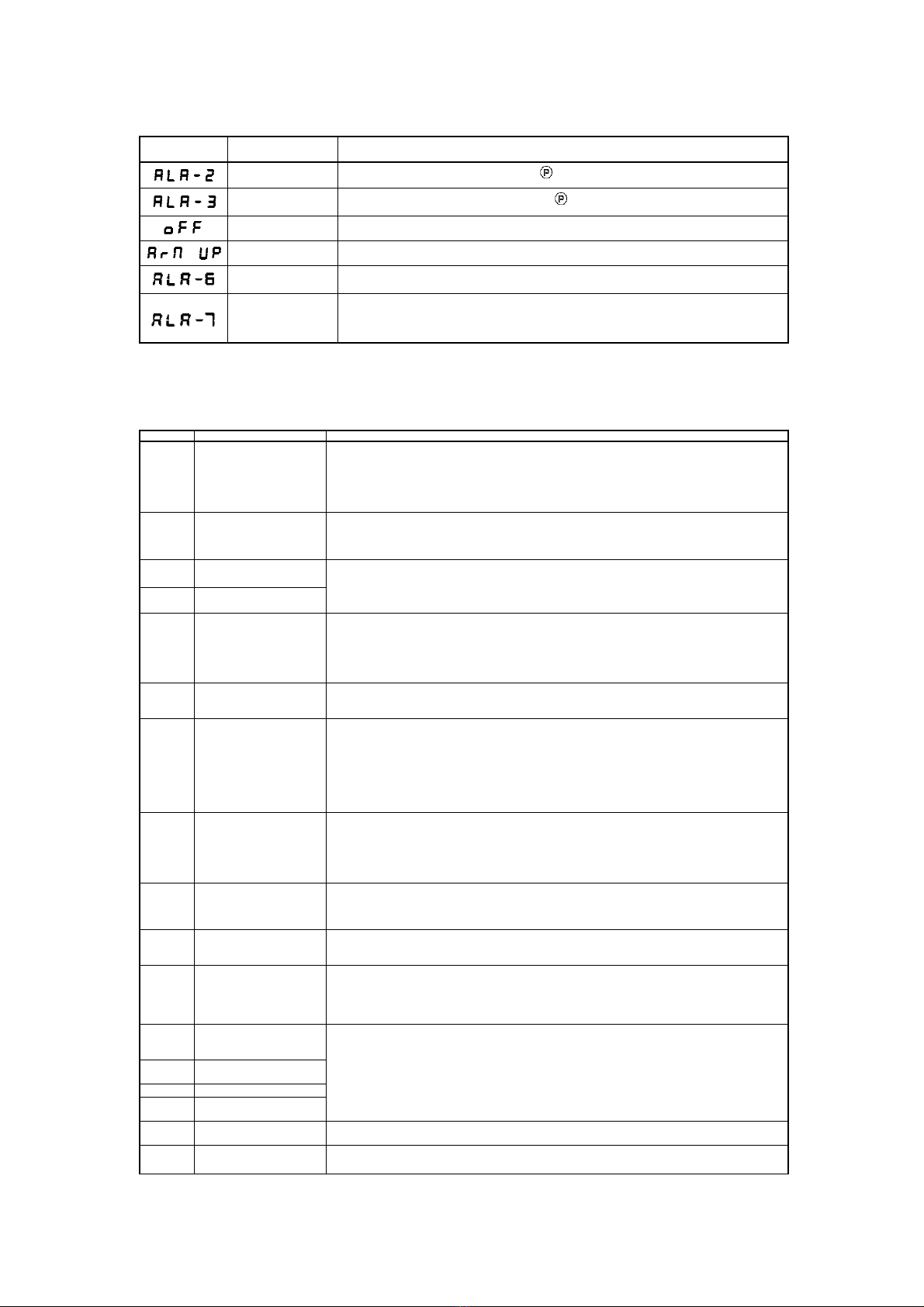
Alarm code Description Corrective
Stitch counter alarm The stitch counter reaches the limit. Press key to cancel the alarm and reset the counter.
Trimming counter
alarm The trimming counter reaches the limit. Press key to cancel the alarm and reset the counter.
Power off alarm Please wait for 30 seconds, then turn on the power switch
Safety switch alarm Adjust the machine to the correct position.
The speed controller
is abnormal
Disconnect the power supply and check whether the line contact of the speed controller is
detached
Stepper motor out of
position Adjust the parameter item P123 to check the installation position of the stepping motor
4.4 Error mode
If the error code appears, please check the following items first:1.Make sure the machine has been connected correctly; 2. Confirm that the
control box match with the machine head. 3. Confirm factory reset is accurate
Error Code Description Solution
Err-01 Arm shaft motor
hardware overcurrent
1. Turn off the system power, and turn it on again after 30 seconds.
2. Please enter P61 to check the initial angle of the arm shaft motor.
3. Check whether the arm shaft motor encoder and electronic control are damaged or in other poor
conditions. If so, replace them in time.
4. If the system still does not work properly after troubleshooting and restart.
Please contact your local service provider or call 4008876858.
Err-03 System undervoltage
Disconnect the power supply of the controller and check whether the input power supply voltage is
lower than 176V. If so, please restart the controller after the voltage returns to normal. If the voltage
returns to normal, it still does not work properly after the controller starts up.
Please contact your local service provider or call 4008876858.
Err-04 Overvoltage during
shutdown
Disconnect the controller power and check whether the input power voltage is higher than 264V. If
so, please restart the controller after the voltage returns to normal. If the voltage returns to normal, it
still does not work properly after the controller starts up.
Please contact your local service provider or call 4008876858.
Err-05 Overvoltage during
operation
Err-06 Electromagnet circuit
failure
1. Turn off the system power, check whether the electromagnet connection is correct and whether
there is any loose or damaged part. If so, replace it in time.
2. Unplug the 14-pin plug on the electric control to confirm whether the electric control is normal. If
the electric control is normal, please check whether the electromagnetic circuits are damaged.
3. If the system still does not work after troubleshooting and restart.
Please contact your local service provider or call 4008876858.
Err-07 Current detection circuit
failure
Turn off the system power, and turn on the power again after 30 seconds to see whether it can work
properly. Try a few times again. If the fault occurs frequently, please contact your local service
provider or call 4008876858.
Err-08 Arm shaft motor stalled
1. Please check whether there is any foreign object wrapped around the machine head, whether
there is any thread residue stuck in the rotating shuttle, and whether the eccentric wheel of the
machine is stuck.
2. Disconnect the power supply of the controller and check whether the input plug of the arm shaft
motor power supply is detached, loose, or damaged.
3. Please enter P61 to check the initial angle of the arm shaft motor.
4. If the system still does not work properly after troubleshooting and restart.
Please contact your local service provider or call 4008876858.
Err-10 Panel communication
failure
1. Please check whether the connection between the operation panel and the electric control is
drops off, loose, or broken.
2. Please check whether the connection cable of the pedal speed controller is drops off, loose, or
damaged.
3. If the system still does not work properly after troubleshooting and restart.
Please contact your local service provider or call 4008876858.
Err-11 Head stop signal failure
1. Check whether the connection between the arm shaft motor encoder and the controller is loose.
2. Replace the arm shaft motor encoder.
3. If the system still does not work properly after troubleshooting and restart.
Please contact your local service provider or call 4008876858.
Err-12 Arm shaft motor initial
angle detection failure
1. Please enter P61 to check the initial angle of the arm shaft motor.
2. Please try 2-3 times again after power off. If it still fails.
Please contact your local service provider or call 4008876858.
Err-13 Arm shaft motor zero
position fault
1. Turn off the power of the system, check whether the arm shaft motor encoder connector is loose,
or drops off. Restore it to normal and restart the system.
2. Replace the arm shaft motor encoder.
3. If the system still does not work properly after troubleshooting and restart.
Please contact your local service provider or call 4008876858.
Err-14
Master control eeprom
components read/write
failure
Turn off the system power, and then turn on the power again after 30 seconds. If the controller still
does not work properly, please contact your local service provider or call 4008876858
Err-15 Arm shaft motor
overspeed protection
Err-16 Arm shaft motor reverse
Err-17 Master control restart
failure
Err-18 Arm shaft motor overload Check whether the arm shaft motor is stalled. If not, please contact your local service provider or call
4008876858.
Err-20 Alarm for oil shortage
every 8 hours
Check whether the oil level of the machine is sufficient. If the problem is still not resolved after filling
up the oil volume, please contact your local service provider or dial 4008876858.

第10页共 10 页
Err-21 Arm shaft motor stalled
1. Please check whether there is any foreign object wrapped around the machine head, whether
there is any thread residue stuck in the rotating shuttle, and whether the eccentric wheel of the
machine is stuck.
2. Disconnect the power supply of the controller and check whether the input plug of the arm shaft
motor power supply is detached, loose, or damaged.
3. Please enter P61 to check the initial angle of the arm shaft motor.
4. If the system still does not work properly after troubleshooting and restart.
Please contact your local service provider or call 4008876858.
Err-30 Password lock shutdown
alarm
The machine has reached the set time. If further use is required, please contact your local service
provider or call 4008876858.
Err-31 Backstitch step motor
zero position fault
1. Check whether the backstitch step motor, swing seat, and teeth are stuck. After the normal state
is restored, restart the system.
2. Check whether the backstitch step encoder is damaged or in other poor conditions. If so, replace it
in time.
3. If the system still does not work properly after troubleshooting and restart.
Please contact your local service provider or call 4008876858
Err-32 Backstitch step motor
hardware overcurrent
1. Turn off the system power, and then turn on the power again after 30 seconds
2. Check whether the backstitch step motor, swing seat, and teeth are stuck. After returning to the
normal state, restart the system.
3. If the system still does not work properly after troubleshooting and restart.
Please contact your local service provider or call 4008876858
Err-33 Stepper motor current A
detects loop faults
Turn off the system power, and then turn on the power again after 30 seconds. If the controller still
does not work properly, please contact your local service provider or call 4008876858.
Err-34 Stepper motor current B
detects loop faults
Turn off the system power, and then turn on the power again after 30 seconds. If the controller still
does not work properly, please contact your local service provider or call 4008876858.4.
Err-35 Stepper motor Hall signal
failure
1. Check whether the stepping encoder and electric control are damaged or not. If so, replace them
in time
2. Turn off the system power, and then turn on the power again after 30 seconds.
3. If the system still does not work properly after troubleshooting and restart.
Please contact your local service provider or call 4008876858
This manual suits for next models
1
Table of contents
Other Jack Sewing Machine manuals