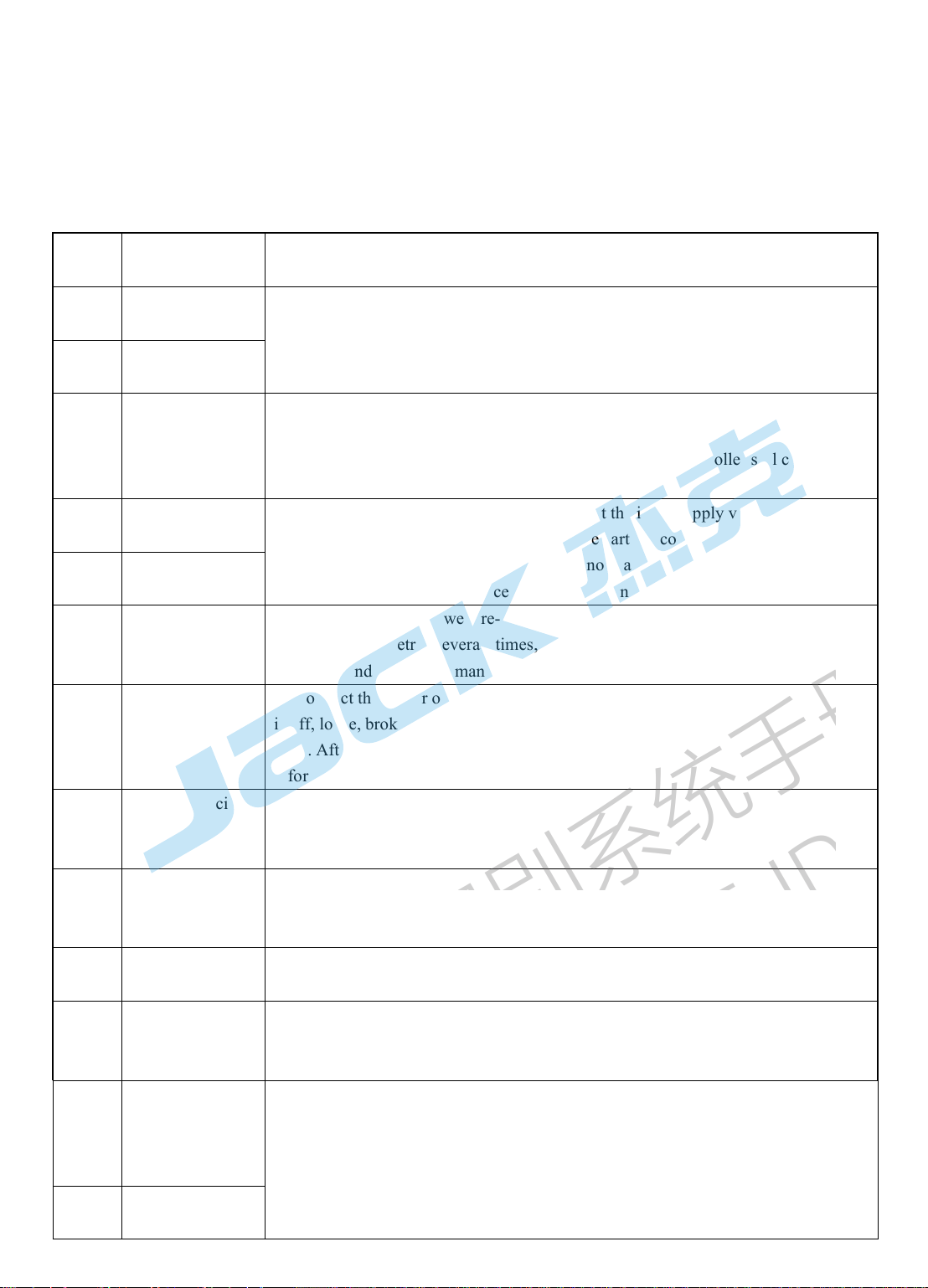
Jack ZB-A2S User manual

1/8
ZB-A2S Operation Manual
Safety instruction
·
Please
read
this
manual
carefully,
also
with
related
manual
for
the
machinery
before
use
the
controller.
·
For
installing
and
operating
the
controller
properly
and
safely,
qualified
personnel
are
required.
·
Please
try
to
stay
away
from
arc
welding
equipment,
in
order
to
avoid
electromagnetic
interference
and
malfunction
of
the
controller.
·
Keep
in
room
bellow
45
°
and
above
0
°
·
o
not
humidity
below
30%
or
above
95%
or
dew
and
mist
of
places.
·
Install
the
control
box
and
other
components,
turn
off
the
power
and
unplug
the
power
cord.
·
To
prevent
interference
or
leakage
accidents,
please
do
the
ground
work,
the
power
cord
ground
wire
must
be
securely
connected
to
an
effective
way
to
earth..
·
All
parts
for
the
repair,
provided
by
the
Company
or
approved
before
use.
·
performing
any
maintenance
action,
you
must
turn
off
the
power
and
unplug
the
power
cord.
There
are
dangerous
high
voltage
control
box,
you
must
turn
the
power
off
after
one
minute
before
opening
the
control
box.
·
This
manual
marked
with
the
symbol
of
the
epartment
of
Safety
Precautions
must
be
aware
of
and
strictly
adhered
to,
so
as
not
to
cause
unnecessary
damage.
1 Product installation
1.1 Product specifications
Model A2S voltage AC 220±20% V
Frequency 50Hz/60Hz Max output power 550W
1.2 Plug connection
Connecting plugs of the the pedal or machine head to the related socket on the control box. More
details please check the below map 1-1.
Figure 1-1 A2S series control box
1
pedal & upgrade socket;
②
Electromagnet and Machine head button socket.
①
②
企业识别系统手册
CORPORATE IDENTITY SYSTEM
GUIDELINES

2/8
1-2 Controller interface definition
Note: please check if the plug and socket match or the direction of the plug is right hen e can’t
plug in under normal condition.
1.3 Wiring and grounding
Please make qualified grounding system with professional technicians. Make sure the AC plug is
grounded safely before power on. The yellow and green wire is for grounding, and please make sure it is
grounded before operating thus can prevent abnormal conditions.
Note: please don’t t ist or press hile grounding po er ire, signal ire, grounding ire etc for
making sure safety
2 Operation panel instructions
2.1Operation panel display instructions
According to the system working state, The igital pipe of the operation panel will display the current
sewing status Contains (stop needle position, thread trimming indicaton). The operation panel looks as
follows.
2-1 operation panel
企业识别系统手册
CORPORATE IDENTITY SYSTEM
GUIDELINES

3/8
2.2The description of each key function
number picture diagram Function description
1Enter the parameter
area function key Parameter function entry key
2Parameter view save
key View and save the selected parameter number
3 Speed plus Initial standby speed plus
4 Speed reduction Initial standby speed reduction
5Left key 1
、
adding
2
、
adding
6 Right shift key 1
、
reducing
2
、
reducing
7 isplay cutover key Toggles the window display and needle setting
for the ABC segment or EFGH segment
8 Front safety switch Reinforcement sewing part(A-B)
one time or two times Before switching
9 Back safety switch Reinforcement sewing part(C- )
one time or two times Before switching
10 W stitch / multi-section
stitch
Short press to select W sewing mode /
long press to select multi-segment sewing mode
11 Restore factory settings
key Press and hold 3S to restore the factory settings
12 Free stitch/ cut thread
Short press to select free stitch mode /
long press to turn on the thread trimming
function or off it
13 Stop needle position
selection/clip thread
Switch on/off the tension post function when
pressing the top/down needle position shortly
3 Parameters adjustments
3.1 Method to enter into operators parameters and saving
Press for a long time and then press shortly then enters into parameters。Press or to
modify related parameters。If not modified, press to back;if modified successfully, press then
shows ok and back to the main menu. Press to exit the parameters mode.
3.2 Method to enter into technicians parameters and saving
Press + for a long time and power on, same method as operators parameter.
企业识别系统手册
CORPORATE IDENTITY SYSTEM
GUIDELINES

4/8
3.3 Speed adjustment
Press or to change the speed. 50 difference once a time and can press constantly.
3.4 Factory setting
Press for factory setting.
3.5 Method to monitors mode
Press and shows monitors number,press or to change the monitors number,press
to enters into the related value of monitors number, press again to return the monitors reference
number.(if the monitor number is 24、25、26、28, press shortly when shows the related value then can
back to the monitors number,press to save the current monitors’ value and if shows ok, it means saved
successfully. Press shortly and exit the monitors mode.)
Note: ho to set needle position, enters parameter 24 and adjust hand heel to change the needle position, then
press to check the value, then press for a long time (needle position ill change accordingly), press to
exit monitors mode.
3.6 Parameters
3.6.1 Operators parameter
param
eters
descriptions Factory
value
range num
ber
descriptions Factory
value
range
P00 Starting speed (r/min) 200 100-80
0P23
Curve mode of the pedal
0
:
straight line
1
:
two phase slope
2
:
curve
(
s uare
)
3
:
S
curve
0 0-3
P01 Highest speed (r/min) 3500 200-50
00
P24 Thread trimmer position of the
pedal
150 0-4095
P02 Multi-phase speed
(
r/min
)
3000 200-35
00
P25 Back safty stitch(sucking) 27 1-120
P03 Needle position
0
:
top
1
:
down
1 0-1 P26 Front safty stitch(releasing) 18 1-120
P04 Front bar tack sewing
speed
(
r/min
)
1800 200-30
00
P29 Auxiliary parameters
0
:
a uare
1:
cube
1 0-1
P05 Back bar tack sewing
speed(r/min) 1800 200-30
00 P30
Powerful when the motor
under low speed 0
:
normal
1
—
31
more
powerful
0 0-31
P06 W sewing speed(r/min) 1800 200-30
00
P31 Thread trimmer strength 40 10-60
P07 Slow starting sewing
speed(r/min) 800 100-80
0P32
Tread tension magnet
time(from beginning to full
energy)
40 1-200
企业识别系统手册
CORPORATE IDENTITY SYSTEM
GUIDELINES

5/8
3.6.2 Technicians parameters
param
eters
descriptions Factory
value
range num
ber
descriptions Factory
value
range
P44
Delaying time when
touching the front pedal
0
:
off
1-300
:
on
0 0-300 P68 Maximum speed setting (r/min) 3700 200-500
0
P45 Working time of presser
foot
every
period
(
ms
)
1 1-10 P69 Stich uantityby testing the top
thread
5 0-100
P46 Closing time of presser
foot
every
period
(
ms
)
2 1-10 P70 Presser foot position setting 800 0-4095
P47 Reverse pulling after
trimming
360 200-36
0
P71 Slowly presser foot 125 100-150
P48 Back sewing magnet
protection
time
(
s
)
10 1-60 P72 Initial position when pressing
the
pedal
400 0-4095
P49 Trimming time(r/min) 250 100-50
0
P73 Ending position of pedal under
low
speed
700 0-4095
P50
Duration of presser foot
magnet to the power
fullest
(
ms
)
150 100-50
0P74 Maximum value of pedal 4000 0-4095
P51
Working time of presser
foot magnet every period
(
ms
)
3 1-10 P75 Mid position of pedal 1650 0-4095
P52 Presser foot delaying
time
(
ms
)
200 100-50
0
P76 Back sewing magnet from
starting
to
the
fullest
time
(
ms
)
60 1-200
P08 Slow starting sewing
stitches
1 1-9 P33 Tread tension magnet period
(from
beginning
to
full
energy)
6 1-10
P09
Slow starting sewing
switch
0
:
off
1
:
on
1 0-1 P34 Multi-phase mode
0:off 1:on 0 0-1
P10 W sewing stitch
(
sucking
)
27 1-120 P35 Thread tension switch 1 0-1
P11 W sewing stich
(
releasing
)
18 1-120 P36 Angle of finishing testing the
top
thread
25 1-360
P12 Half stitch delaying
time
(
ms
)
150 1-180 P37 Closing time of tension post
period
4 1-10
P13 One stitch delaying
time
(
ms
)
180 150-25
0
P38 Thread trimer
0:
off
1
:
on
1 0-1
P14 Adding stitch sewing
speed
(
r/min
)
200 100-50
0
P39 Presser foot switch during
sewing
0:
off
1
:
on
0 0-1
P15
Adding stitch type
0
:
by time 1
:
half
stitch
2
:
one
stitch
0 0-2 P40 Presser foot switch after
trimming 0:off 1:on 0 0-1
P18 Front safty sewing stitch 27 1 - 120 P41 Stitch number 1 1-50
P19 Back safty sewing stitch 18 1 - 120 P42 Stitch number calculation 9999 1-9999
P21 Manual back sewing
speed (r/min) 5000 200-50
00 P43
Stitch counting number
0
:
off 1
:
up 2
:
down 3
:
alarm and stop when arrive the
highest point
4
:
alarm and stop when arrive
the lowest point
5
:
alarm and run when arrive
the highest point
6
:
alarm and run when arrive
the
lowest
point
0 0-6
P22
Value of back sewing
fuction when adding
stitch
8 0-9999
企业识别系统手册
CORPORATE IDENTITY SYSTEM
GUIDELINES

6/8
P53
Automatic presser foot
function
0
:
manual
1
:
automatic
0 0-1 P77 Motor direction
0
:
opposite 1
:
converse 0 0-1
P54 Closing time of presser
foot
every
period(ms)
5 1-10 P78 Tension post starting angle 150 10-359
P55 Top thread testing switch 0 0-1 P79 Tension post finishing angle 280 0-359
P56
Automatic top needle
position
0
:
manual
1
:
automatic
1 0-1 P80 Trimmer starting angle 0 0-359
P57 Presser foot magnet
protection
time(s)
10 1-30 P81 Trimmer enforcement angle 100 0-359
P58 Top needle position
angle
67 0-359 P82 Angle of after trimming 160 0-359
P59 Down needle position
angle
176 0-359 P83 Confirmation time of presser
foot
pedal
(
ms
)
50 1-500
P60 Testing speed(r/min) 3000 200-50
00
P84 Confirmation time of safety
switch
alarm
(
ms
)
300 1-500
P61 Aging operation time(s) 3 1-255 P85 Restoring time of safety sitch
alarm
(
ms
)
50 1-200
P62
Special test mode
0: normal 1:simple
sewing
2:initial angle test
3:automatic testing
mode
0 0-3 P86 Transition point speed between
two phase slope(r/min) 1500 0-4000
P63 Aging stopping time(s) 2 1-255 P87 Analog uantity between two
phase
slope
2700 0-4095
P64 Retain 0 0-1 P88 Piece number unit 1 1-50
P65
Factory setting
0: no operation
1:factory value
2:technicians
value
0 0-2 P89 Piece number calculation 9999 1-9999
P66 Machine head safety
switch test 1 0-1 P90
Piece counting number
0
:
off 1
:
up 2
:
down
3
:
alarm and stop when arrive
the highest point
4
:
alarm and stop when arrive
the lowest point
5
:
alarm and run when arrive
the highest point
6
:
alarm and run when arrive
the
lowest
point
0 0-6
P67 Logic of machine head
protection switch 1 0-1
3.6.3 Monitors parameters
Number Descriptions Number Descriptions Number Descriptions
010 Stitch number 020 Voltage 025 Max value of front pedal
011 Piece number 021 speed 026 Value for mid pedal
012 Number of stitches
per sewing 022 Phase current 028 Thread trimmer speed of
the pedal
013 Panel version
number 023 Initial angle 030-037 History errors
018 Controller version
number 024 Mechanical angle
企业识别系统手册
CORPORATE IDENTITY SYSTEM
GUIDELINES

7/8
4 Error code
4.1 Error code table
If the system shows error or alarm, please first check the following items:
1. first, confirm if the machine's connection cable is intact; 2. Confirm whether the electronic control
box and the machine is matched or not; 3. Confirm whether the factory reset is accurate or not.
Error
code Code meaning Countermeasure
Err-01 Hardware
overcurrent Turn off the system power, re-connect the power after 30 seconds, if the controller
still can not work, replace the controller and notify the factory.
Err-02 Software
overcurrent
Err-03 System
undervoltage
isconnect the controller power and check if the input supply voltage is low (under
110V). If the supply voltage is low, restart the controller after the voltage has
returned to normal. If the voltage is still normal, start the controller still can not
work properly, please replace the controller and notify the factory.
Err-04 Excessive
shutdown
isconnect the controller power and check that the input supply voltage is high
(above 275V). If the supply voltage is high, restart the controller after the voltage
has returned to normal. If the voltage is still normal, if restart the controller still can
not work properly, please replace the controller and notify the factory.
Err-05 Running over
voltage
Err-07 Current detection
circuit failure
Turn off the system power, re-connected after 30 seconds to observe whether the
normal work. Retry several times, if the fault occurs frequently, replace the
controller and inform the manufacturer.
Err-08 Motor stalled
isconnect the power of the controller, check whether the motor power input plug
is off, loose, broken, whether there is foreign body wrapped around the machine
head. After resetting the system still does not work, replace the controller and
inform the factory.
Err-09
Brake circuit
failure
Turn off the system power, check the power board of white brake resistor connector
is loose or fall off, put it tight and restart the system. If it still does not work, replace
the controller and inform the manufacturer.
Err-10
HMI
communication
failure
Check whether the connection between the control panel and the controller is off,
loosening, breaking, and restarting the system after returning to normal. If it still
does not work, replace the controller and inform the manufacturer.
Err-12 Motor initial angle
detection fault
Please try restart 2-3 times, if still reported failure, please replace the controller and
notify the factory.
Err-13
Motor optical
encoder signal
missing
Turn off the system power, check the motor sensor connector is loose or off, to
return to normal after the restart system. If it still does not work, replace the
controller and inform the manufacturer.
Err-14
EEPROM
Motherboard read
and write
EEPROM fault Turn off the system power, restart the system after 30 seconds, if still can not work,
please replace the controller and notify the factory.
Err-15 Motor overspeed
protection
企业识别系统手册
CORPORATE IDENTITY SYSTEM
GUIDELINES

8/8
Err-16 Motor reversal
Err-18 Motor overload
4.2Safety alarm table
Error code Code meaning Solutions
ALR-2 Stitch number alarm Means the number of pins has reached the set limit.Press P key
to cancel the alarm and count again.
ALR-3 Package number alarm Means the number of packages has reached the set limit.Press P
key to cancel the alarm and count again.
A-UP Flip switch alarm Put the machine to ensure that the flip switch to restore
5 Foot pedal sensitivity adjustment
1) The pedal movement starts from the initial position①(parameter 75), slowly stepping forward to ②
(72 + 75 parameter) to start the low-speed sewing, and then proceed to step (75 + 73) to start accelerating
eep step to ④(74 parameters) to achieve the highest speed. Between ② ③ segment to maintain the
starting speed, between ③④segment is the no-level speed control process;
2) When the foot pedal starts from the initial position ①(parameter 75) Slowly after the step to ⑤(24
parameters) automatically cut the line when the finished the cutting action;
3) Make sure the parameter value should be arranged as below: (parameter No. 24) <(parameter No. 70)
<(parameter 75) <(parameter 75 + 72) <(parameter 75 + 73) <(parameter 74)
4) It can be monitored by the mode of 025,026,028 parameters in real time to monitor the pedal analog
maximum, pedal back to the voltage sampling value, pedal trimming voltage sampling value, the operation
mode with the stop position on the set, different positions of the pedal. The sampling value is used as the
reference value for each parameter. If the machine is too sensitive, touch the pedal machine to start running,
may be appropriate (if the machine is too sensitive, it is appropriate to reduce the 72 parameters (not less
than the return position parameter 75), you can improve the sensitivity of the previous step; Increase the 72
parameters; if not easy to fill the needle, a little pre-step, the speed of the rapid increase caused by forward
needle, may be appropriate to increase the 73 parameters or reduce the 72 parameters (that is, increase the
pedal low speed range), can also be Reduce the initial seam speed (parameter 00)appropriate.
企业识别系统手册
CORPORATE IDENTITY SYSTEM
GUIDELINES
Table of contents
Other Jack Sewing Machine manuals