manuals.online logo
Brands
  1. Home
  2. •
  3. Brands
  4. •
  5. Jamara
  6. •
  7. Motorized Toy Car
  8. •
  9. Jamara Splinter BL User manual

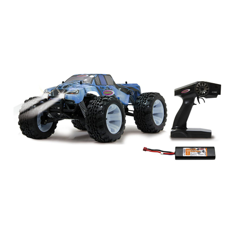
Jamara Splinter BL User manual

This manual suits for next models

4

Other Jamara Motorized Toy Car manuals

Jamara Volkswagen T1 2,4 GHz User manual

Jamara

Jamara Volkswagen T1 2,4 GHz User manual

Jamara VW Käfer User manual

Jamara

Jamara VW Käfer User manual

Jamara 460205 User manual

Jamara

Jamara 460205 User manual

Jamara Mercedes-Benz Arocs User manual

Jamara

Jamara Mercedes-Benz Arocs User manual

Jamara Ferrari LaFerrari Aperta User manual

Jamara

Jamara Ferrari LaFerrari Aperta User manual

Jamara Mercedes-AMG GL 63 User manual

Jamara

Jamara Mercedes-AMG GL 63 User manual

Jamara Quad 12 V User manual

Jamara

Jamara Quad 12 V User manual

Jamara 404940 User manual

Jamara

Jamara 404940 User manual

Jamara Mover Stuntcar User manual

Jamara

Jamara Mover Stuntcar User manual

Jamara Mercedes Benz SL65 AMG User manual

Jamara

Jamara Mercedes Benz SL65 AMG User manual

Jamara 405002 User manual

Jamara

Jamara 405002 User manual

Jamara Ice Tiger EP BL User manual

Jamara

Jamara Ice Tiger EP BL User manual

Jamara Liebherr R 936 User manual

Jamara

Jamara Liebherr R 936 User manual

Jamara Dakar EP 2,4 GHz User manual

Jamara

Jamara Dakar EP 2,4 GHz User manual

Jamara Deluxe Car User manual

Jamara

Jamara Deluxe Car User manual

Jamara Mercedes Actros Muldenkipper 2,4 GHz User manual

Jamara

Jamara Mercedes Actros Muldenkipper 2,4 GHz User manual

Jamara Dakar EP 2,4 GHz User manual

Jamara

Jamara Dakar EP 2,4 GHz User manual

Jamara McLaren P1 User manual

Jamara

Jamara McLaren P1 User manual

Jamara Jeep Wrangler Police 2,4 GHz User manual

Jamara

Jamara Jeep Wrangler Police 2,4 GHz User manual

Jamara Audi R8 LMS GT3 Bricks 2,4GHz User manual

Jamara

Jamara Audi R8 LMS GT3 Bricks 2,4GHz User manual

Jamara Mercedes-AMG G63 User manual

Jamara

Jamara Mercedes-AMG G63 User manual

Jamara Strong Bull User manual

Jamara

Jamara Strong Bull User manual

Jamara AUDI RS5 User manual

Jamara

Jamara AUDI RS5 User manual

Jamara LIEBHERR User manual

Jamara

Jamara LIEBHERR User manual

Popular Motorized Toy Car manuals by other brands

Reely Dune Fighter 3S operating instructions

Reely

Reely Dune Fighter 3S operating instructions

REVELL 1970 Chevelle SS 454 manual

REVELL

REVELL 1970 Chevelle SS 454 manual

Team Losi Micro Rally Car Operation guide

Team Losi

Team Losi Micro Rally Car Operation guide

Eduard Humber Scout Car Mk.I exterior quick start guide

Eduard

Eduard Humber Scout Car Mk.I exterior quick start guide

REVELL 68 CHEVY CHEVELLE SS 396 manual

REVELL

REVELL 68 CHEVY CHEVELLE SS 396 manual

Schumacher Pro Cat instruction manual

Schumacher

Schumacher Pro Cat instruction manual

Tamiya TT-01 TYPE E instruction manual

Tamiya

Tamiya TT-01 TYPE E instruction manual

Eduard Krupp Protze 6x4 1/48 quick start guide

Eduard

Eduard Krupp Protze 6x4 1/48 quick start guide

New Bright 61072UEP quick start guide

New Bright

New Bright 61072UEP quick start guide

Team Durango DEX410v5 manual

Team Durango

Team Durango DEX410v5 manual

PLAYMOBIL 9536 manual

PLAYMOBIL

PLAYMOBIL 9536 manual

Atomic BZ3 instruction manual

Atomic

Atomic BZ3 instruction manual

Aiyaplay 370-290V00 user manual

Aiyaplay

Aiyaplay 370-290V00 user manual

ZEROTRIBE Zetricks ZT1144 instruction manual

ZEROTRIBE

ZEROTRIBE Zetricks ZT1144 instruction manual

INJUSA 412 Assembly instructions

INJUSA

INJUSA 412 Assembly instructions

Maverick MSC-30BR-WP instruction manual

Maverick

Maverick MSC-30BR-WP instruction manual

Land of B. Rollin' Riders quick start guide

Land of B.

Land of B. Rollin' Riders quick start guide

TLR 22SCT 2.0 user manual

TLR

TLR 22SCT 2.0 user manual

manuals.online logo
manuals.online logoBrands
  • About & Mission
  • Contact us
  • Privacy Policy
  • Terms and Conditions

Copyright 2025 Manuals.Online. All Rights Reserved.

13/22
Frequency bands: 2.4Ghz Frequency range: 2405,5 MHz - 2475,0 MHz EIRP: 49,09 mW (max. power transmitted)
Splinter EP | BL
2,4 GHz
No. 053270 EP
No. 053271 EP LiPo
No. 053275 BL LiPo
FR - Notice d’assemblage
GB - Instruction
Déclaration de la conformité
Par la présente, JAMARAe.K. déclare que les produits „Splinter EP | BL2,4 GHz, No. 053270,
No. 053271, No. 053275“ est conforme à la Directive 2014/35/UE, 2014/53/UE et
2011/65/UE.
Le texte intégral de la déclaration de conformité CE est disponible via l‘adresse internet
suivante: www.jamara-shop.com/Conformity
Certicate of Conformity
Hereby JAMARA e.K. declares that the products „Splinter EP | BL 2,4 GHz, No. 053270,
No. 053271, No. 053275“ comply with Directives 2014/35/EU, 2014/53/EU and 2011/65/EU.
The full text of the EU Declaration of Conformity is available at the following Internet
address:
www.jamara-shop.com/Conformity
Remarques générales
La société JAMARA e. K. n’est pas responsable de dommages, que ce soit au niveau du modè-
le ou causé par celui-ci, résultant d’une utilisation non appropriée. Seul le client est responsable
concernant la mise en oeuvre et l’utilisation conforme du matériel; cela va de l’assemblage, en
passant par la charge des accus et allant jusqu’au choix du lieu d’utilisation. Pour cela, veillez à lire
attentivement la notice d’utilisation, elle contient d’importantes informations ainsi que les consignes
de sécurité.
General information
Jamara e.K. is not liable for any damage caused to the product itself or through this, provided this
is due to improper operation or handling errors. The Customer alone bears the full responsibility for
the proper use and handling, including without limitation, the assembly, the charging process, the
use and choice of the operation area. Please refer to the operating and user instructions, it contains
important information and warnings.
Attention!
Avant l’utilisation: Allumez en premier l’émetteur puis votre modèle.
Après utilisation: Arrêtez le modèle en premier puis votre radiocommande.
●N’utilisez jamais le modèle à une distance hors de votre visibilité. La visibilité maximale ainsi
que la portée maximale dépendent de plusieurs facteurs tels que le temps, le lieu d’utilisation et
 lesprésentesfréquencesperturbatrices.Pourcela,avantchaqueusage,veuilleze󰀨ectuerun
 testdevisibilitéetdeportéeavecunedeuxièmepersonnequitientlemodèlexéetvériezles
réactions du modèle en usage en cas de pertes de signal due par exemple à des piles usées ou
à un émetteur éteint.
Attention!
Before operating: Switchthetransmitteronrstthenthemodel.
When nished: Firstswitcho󰀨themodelthenthetransmitter.
● Never operate your model beyond sight. Both the maximum visibility as well as the max. range
of your model will depend on many factors such as weather, location and interfering
frequencies. Therefore, before each use perform a range test with a second person securely
holding the model and also check how the model reacts if there is a signal failure e.g. when
empty transmitter batteries are installed.
Ce modèle réduit n’est pas un jouet!
Attention: Ne convient pas aux enfants de moins de 36 mois.
DANGER D‘ETOUFFEMENT!
Contient des pièces petites qui peuvent être avalées.
Ne pas laisser à la portée de petits enfants.
This model is not a toy!
Warning: Not suitable for children under 36 month. RISK OF SUFFOCATION!
Keep away necessarily from children.
Contains small parts which can be swallowed.
Accessoires conseillé Recommended Tool
Avant de mettre en marche toute l‘unité il faut lire attentivement le mode d‘emploi.
Attention! La mise en garde et les consignes de sécurités sont à lire entièrement
pour votre sécurité et éviter tout accidents et blessures.
Read the complete instructions and security instructions carefully before using the model.
Caution! Please fully and carefully read warnings/ safety instructions. These are for
our own security and can avoid accidents/injuries.
Ceproduitestunarticledemodélisme.Celasigniequelevéhiculedoittoujoursfairel‘objetd‘un
entretien (contrôle des dommages, contrôle des raccords vissés, nettoyage, etc....). Les pièces
d‘usure telles que l‘engrenage principal, le pignon du moteur, la tête de rotule etc. s‘usent avec le
temps et doivent donc être remplacées. Il n‘est pas toujours possible d‘éviter les collisions, c‘est
pourquoi les dommages causés par les collisions doivent également être réparés ou remplacés.
Lespiècesd‘usureoulespiècesdéfectueusesduesàdesaccidentsouàunentretieninsu󰀩santne
sont pas couvertes par la garantie, les coûts et les réparations doivent être assumés par l‘acheteur
lui-même.
This product is a model building article. This means that the vehicle must always be serviced (check
for damage, check screw connections, clean etc...). Wear parts such as the main gear, motor pinion,
bone socket, etc. will wear out over time and must therefore be replaced. Crashes cannot always be
avoided, so crash damage must also be repaired or replaced. Wear parts or defective parts due to
crashesorinsu󰀩cientmaintenancearenotcoveredbywarranty,costsandrepairsmustbecovered
by the buyer himself.
No. 190065
Appareil de mesure
d’inclinaison
Camber adjusting Tool
No. 232060
Ruban adhésif double face
Doublesided power tape
No. 232423 medium
Freinlet
Nut lock
No. 281730
Paire de coseaux Lexan
Lexan scissors
No. 059273 1:10
Goupille de carrosserie
Body clips
No. 505401 petit/small
Goupille de carrosserie
Body clips
No. 153059
X-Peak 80 V2
Chargeur
Charger
2
NiMh
1
Version 053270
2
3
4
5
6
8
8
7
Eléments livrés
1. Modèle
2. Télécommande
3. Antenne
4. Clips de précontrainte du
ressort
5. Fiche de raccordement
6. Accu LiPo (053271/053275)
7. Chargeur LiPo
8. Accu NiMh (053270)
9. Chargeur USB NiMh
Accessiores:
• Télécommande: 4 x AA 1,5V,
Nr. 140267 (4 pièces)
Donées techniques:
• Dimensions:
~ 410 x 270 x 156 mm
• Poids:
~ 2519,4g (No. 53270/053271)
~ 2430,2g (No. 053275)
• Accu:
NiMh 7,2 V 2000 mAh
(No. 053270)
LiPo 7,4 V 5000mAh
(No. 053271 / 053275)
• Moteur:
270 W
(No. 053270 / 053271)
420 W 3200 KV
(No. 053275)
Informations sans garantie.
Sous réserve d‘erreurs et de
modicationstechniques.
Box contents
1. Model
2. Transmitter
3. Antennas
4. Clip for spring tension
5. Binding Plug
6. Battery LiPo (053271/053275)
7. Charger LiPo
8. Battery NiMh (053270)
9. USB-Charger NiMh
Accessories:
• Transmitter: 4 x AA 1,5V,
No. 140267 (4 pieces)
Technical data:
• Dimensions:
~ 410 x 270 x 156 mm
• Weight:
~ 2519,4g (No. 53270/053271)
~ 2430,2g (No. 053275)
• Battery:
NiMh 7,2 V 2000 mAh
(No. 053270)
LiPo 7,4 V 5000mAh
(No. 053271 / 053275)
• Motor:
270 W
(No. 053270 / 053271)
420 W 3200 KV
(No. 053275)
No responsibility is taken for the
correctness of this information.
Premières étapes - Processus de charge Getting Started - Charging process
NiMh Processus de charge (053270)
Connectez le chargeur USB à un port USB. Nous recommandons un adaptateur secteur USB (2A)
pour la prise secteur ici. Les connexions USB des ordinateurs et des portables ne peuvent généra-
lementpasfourniruncourantsu󰀩santpourchargerlabatterie.Levoyantduchargeurs‘allumeen
vert. Connectez le chargeur USB à la batterie du lecteur NiMh. Le voyant rouge du chargeur USB
signaleleprocessusdecharge.Silacheduchargeuretcelledelabatteried‘entraînement ne
correspondent pas, un adaptateur de charge est fourni avec votre modèle. Lorsque la batterie est
entièrement chargée, le voyant s‘allume en vert. Veillez à ce que le temps de charge ne soit pas
dépassé. Ne chargez pas d‘autres batteries que la batterie NiMh fournie. Le temps de charge moyen
pour la batterie NiMh vide fournie est d‘environ 6 à 8 heures.
Si le voyant clignote, il y a un défaut. Veuillez contacter le service clientèle.
Attention:
Ne chargez que des batteries adaptées à cet usage avec ce chargeur. Les batteries appropriées
sont les batteries nickel-métal-hydrure avec un maximum de 6 éléments, une tension nominale
de 7,2 V maximum et un maximum de 2000mAh. La batterie doit avoir un connecteur Tamiya. La
charge de batteries inadaptées peut endommager le chargeur et la batterie. Risque d‘incendie ! La
connexiondechargeduchargeurnedoitjamaisêtresoudéeoumodiée!
NiMh Charging process (053270)
Connect the USB charger to a USB port. We recommend a USB adapter (2A) for the grounding
receptable.USBportsofcomputersandlaptopsusuallycannotprovidesu󰀩cientcurrenttocharge
the battery. The LED on the charger lights up green. Connect the USB charger to the NiMh drive
battery. The red LED of the USB charger signals the charging process. If the plug of the charger and
the plug of the drive battery do not match, a charging adapter is included with your model. When the
battery is fully charged, the LED lights up green. Make absolutely sure that the charging time is not
exceeded. Do not charge any batteries other than the NiMh battery supplied. The average charging
time for the empty NiMh battery supplied is approx. 6 - 8 hours.
IftheLEDashes,thereisafault.Pleasecontactthecustomerservice.
Caution:
Only charge suitable battery‘s with this charger. Suitable battery‘s are Nickel metal hydride battery‘s
with max. 6 cells, max. 7,2 V nominal voltage and max. 2000mAh. The battery must have a tamiya
plug. The charging of unsuitable battery‘s can cause damage to the charger and the battery‘s.
Fire Hazard! The charging connection of the charger is not allowed to get altered or soldered to a
di󰀨erentbalancerplugtype!
LiPo Processus de charge (053271 / 053275)
Remarques importantes sur l‘adéquation de la batterie:
Veillez à n‘utiliser que des batteries lithium-polymère avec connecteur d‘équilibreur XH. Seules
ces batteries peuvent être utilisées avec le chargeur. Les autres connexions et types de batteries ne
doivent pas être utilisés (risque d‘incendie dû à une inversion de polarité ou à une surcharge).
Veuillez contacter le fabricant de votre batterie pour savoir si votre batterie est adaptée. Seules
des batteries LiPo d‘une capacité d‘au moins 1600mAh doivent être utilisées (sinon, il y a un risque
d‘incendie dû à un courant de charge excessif). Si vous utilisez des batteries d‘une capacité inféri-
eure à 1600mAh, elles doivent être homologuées pour un courant de charge de 1600mA (Speed-
charging). Veuillez demander au fabricant de votre batterie si celle-ci répond à ces exigences.
Vous ne pouvez connecter qu‘une seule batterie au chargeur à la fois. La charge de 2 batte-
ries en même temps n‘est PAS autorisée et endommagera la batterie ou le chargeur (risque
d‘incendie).
LiPo Charging process (053271 / 053275)
Important notes on the suitability of the battery:
Make sure to use only lithium polymer batteries with XH balancer connector. Only these may
beusedwiththecharger.Otherconnectionsandbatterytypesmustnotbeused(rehazarddueto
reverse polarity or overcharging may result).
Pleasecontact themanufacturerofyourbatterytond outwhetheryourbattery issuitable.Only
LiPo batteries with a capacity of at least 1600mAh must be used (otherwise there is a risk of
reduetoexcessivecharging current). If you use batteries withacapacitybelow1600mAh, the
batteries must be approved for a charging current of 1600mA (Speedcharging). Please ask the
manufacturer of your battery if your battery meets these requirements.
You may only connect one single battery to the charger at a time. Charging 2 batteries at
the same time is NOT allowed and will cause damage to the battery or charger (re hazard).
Vous avez acheté un modèle RTR. C‘est-à-dire que le véhicule est en gran de partie
préparépouruneutilisationimmédiate.Cependant,ilestessentieldevériersilemodèle
présente des dommages mécaniques ou électriques avant et après chaque utilisation. Il
fautégalementvérierlastabilitédetouteslespiècesmobilesetl‘étanchéitédesraccords
vissés.
You have purchased a RTR model, which means it should be ready for immediate use after
charging all batteries. You need to check the car, electronics and all plastic parts after each
use to make sure no parts are damaged. Also all the moving parts must be checked for their
clearance, bolts and screws that they are tight.
Seulement pour: / Only for:
Version 053271
Version 053275
Seulement pour:
Only for:
Version 053270
1 2 3
4
3
4x AA
1 2
FR
1. Entrée 100 - 240 V
2. Connecteur pour l‘équilibreur 2 cellules
3. Connecteur pour l‘équilibreur 3 cellules
(Non requis pour ce modèle)
4. LED d‘état
GB
1. Power Slot 100 - 240 V
2. 2S Balancer
3. 3S Balancer
(Not required for this model)
4. Status LEDs
Chargement d‘une batterie
1. Branchez le cordon d‘alimentation du chargeur dans une prise de courant appropriée. Les LEDs
s‘allument en vert et indiquent que le chargeur est prêt à être chargé.
2. Connectez maintenant la batterie vide au chargeur. Les batteries 2S de 7,4 V au connecteur à
3 broches ou les batteries 3S de 11,1 V au connecteur à 4 broches. 3S sur le connecteur à 4
broches. Ne forcez pas et faites attention à l‘inversion de polarité. Les LEDs passent au rouge
après quelques secondes et indiquent que les éléments de la batterie sont en train de se
charger.
Attention : Lors de la connexion d‘une batterie 2S, seules les 2 premières LEDs (Cell1-2)
passent au rouge, la LED 3 (Cell 3) reste verte. Lorsque des batteries 3S sont connectées,
toutes les LEDs sont rouges (Cell1-3).
Dès qu‘un élément de la batterie est plein, la LED correspondante passe au vert. Parce que les
cellules cellules sont chargées individuellement de manière équilibrée, il est possible qu‘une
cellule soit complètement chargée avant les autres. que les autres. Laissez toujours la batterie
sur le chargeur jusqu‘à ce que toutes les cellules connectées soient complètement chargées
(vert). (vert) pour permettre au chargeur d‘équilibrer votre batterie.
Charging a battery
1. Plug the power cord of the charger into a suitable socket. The LEDS light up green and indicate
that the charger is ready for charging.
2. Now connect the empty battery to the charger. 7.4V 2S batteries to the 3 pin connector or 11.1V
3S batteries to the 4 pin connector. Do not use force and pay attention to reverse polarity. The
LEDs change to red after a few seconds and indicate that the battery cells are charging.
Attention:
When connecting a 2S battery, only the rst 2 LEDs (Cell1-2) change to red, LED 3 (Cell 3)
will remain green. When 3S batteries are connected, all LEDs are red (Cell1-3).
As soon as a the battery cell is full, the corresponding LED changes to green. Because the cells
are charged individually in a balanced way, it is possible that one cell is fully charged earlier than
the others. Always leave the battery on the charger until all connected cells are fully charged
(green) to allow the charger to balance your battery
Détection d‘une batterie défectueuse.
Lorsque vous connectez une batterie pleine au chargeur, les voyants deviennent rouges pendant
quelques secondes, puis repassent au vert. Cela signie que la batterie est déjà complètement
chargée.
Détection d‘une batterie défectueuse.
SilesLEDsrestentverteslorsqu‘unebatterievideestconnectée,celasigniequelabatterieest
défectueuse (défaut de cellule ou décharge profonde). Dans ce cas, déconnectez immédiatement la
batterie du chargeur et utilisez une autre batterie.
Detecting a full battery.
When you connect a full battery to the charger, the LEDs will turn red for a few seconds and then
turn green again. This means that the battery is already fully charged.
Detecting a defective battery.
If the LEDs remain green when an empty battery is connected, there is a defect in the battery (cell
defect or deep discharge). In this case, immediately disconnect the battery from the charger and
use another battery.
Mise en place des piles dans l‘émetteur
Placez 4 piles type AA dans l’émetteur.
Inserting batteries into the transmitter
Put 4 AA Batteries into the Transmitter
Informations concernant l‘accumulateur:
Les batteries non rechargeables ne doivent pas être rechargées!
Ne pas ouvrir!
Ne pas jeter au feu!
Ne pas utiliser des piles neuves et usées à la fois!
Ne pas utiliser en même temps des piles alcalines, standard (zinc-charbon) et des accumulateurs!
Les piles rechargeables doivent être retirées du jouet!
Les batteries rechargeables ne peuvent être rechargées que sous la surveillance d‘un adulte!
Les connexions ne doivent pas être court-circuitées!
Battery warning:
Non-rechargeable batteries are not to be recharged!
Do not open!
Donotdisposeofinre!
Do not mix old and new batteries!
Do not mix alkaline batteries, standard (carbon-zinc) or rechargeable batteries!
Rechargeable batteries are to be removed from the toy before being charged!
Rechargeable batteries are only to be charged under adult supervision!
The supply terminals are not to be short-circuited!
Attention!
Débranchez toujours après chaque arrêt la batterie du chargeur. Débranchez aus-
si toujours le chargeur immédiatemment après avoir débranché la batterie de
l´alimentation. Laissez brancher la chargeur ou la batterie peuvent causer des dom-
mages à la batterie, à votzre chargeur ou câble d´alimentation (risque d´incendie).
Danger!
Always disconnect the battery from the charger immediately after charging. Always
disconnect the charger from the power supply immediately after disconnecting the
battery. Inserting the rechargeable battery or charger after charging will result in
damage to the battery, charger or the power supply (re hazard).
4
505080
505081
07 9996
505079
505080
505081
079996
505079
ON/OFF
1
Attention!
Votre modèle possède un système d’accrochage des roues
avant type Pivot. Cela a un bon nombre d’avantages. Celui-ci est
très robuste et facile d’entretien. En sortie d’usine les réglages
sonte󰀨ectués de telle manière que l’écartement des roues ne
permetpasauxaxesd’entraînementsdesortirdesonlogement.
Naturellement, comme pour toutes les voitures, dans la phase
de rodage toutes les parties d’accrochages ainsi que les vis peu-
vent bouger de l’ordre du millimètre. Ce jeu résultant peut faire
ensortequelesaxesd’entraînementsrisquentdesortirdeleur
logement sous contrainte maximale. De ce fait il est très impor-
tantdevérieravantchaqueutilisationlebonmaintiendetoutes
lesvis de xations,les écrous deroues etc. etque le jeudes
pièces de mouvements soient corrects. Si vous tournez la vis
rotule interne 505081 au niveau de l’axe de train Pivot 505079
(voirlistedespiècesderechanges)vousinuencezsurlejeu
ainsi que sur le parallélisme résultant. Il est conseillé de serrer
les Pivot de la même manière en haut et en bas e telle manière
à ce que l’axe, lorsque vous tournez complètement les roues, ne
soit pas sous tension et qu’il ne sorte pas de son logement. Les
vis six pans extérieurs 505080 servent à sécuriser le maintien
des jambes de trains sur la vis rotule.
Attention!
Your vehicle has a pivot front suspension. This has a number of
advantages. It is very robust and easy to maintain. The set-up of
the car has been done so the drive shaft will not pop out. As with
any model, screws and bolts can losen during break-in of the
car. This can result in tolerance of the drive shaft. The drive shaft
can then pop out if high pressure is applied. The inner ball screw
(item No.: 505081) will enable you to adjust the tolerance resul-
tinginneadjustmentsofthetrackwidth.Forbestresultswhen
settingupthe pivot ball forthe rst time, pleasealwaysadjust
the upper and lower pivot in the same way. Fasten as far as the
pivot can still be pulled up and down easyly but not as far that it
will pop out if you give full steering angle. The outer plastic socket
screw (item No.: 505080) is only used for securing of the steering
knuckle. This should not be too tight, otherwise the steering is
notsmoothandthehandlingcanbeadverselya󰀨ected.
Attention!
La tête de rotule avant et arrière absorbe la majeure par-
tie de l‘énergie du moteur et les transmet dans les systèmes
d‘attachement des trains Avant et arriére. De ce faite, les vis de
serrage pans à 6 creux doivent qui maintiennent la tête de rotu-
le sur les arbres de sortie de transmission maintienent avant la
première utilisation et son contrôllés régulièrement ( toute les 5
– 7 utilisations) et ressérrés en cas de besoin L´avant et l´arrière
de la tête de rotule doivent être inséré via l ´anneau en caout-
couch.Veuillezvérierlejeud´arbredetransmission.Lamarge
de manoeuvre devrait être environ de 1-2mm. Vous devrez peut-
être déplacez la tête de rotule pour adapter le jeu. Cela vous
oblige à desserrer les vis de réglage avec un tournevis et régler
le panoramique de la tête de rotule. Veuillez ensuite resserer les
vis de réglage. Au cas contraire, les arbres de transmission de la
tête de rotule ainsi que la tête de rotule et le milieu de l´arbre d
‚entraînementrisqued´êtreendommagé.
Attention!
The front and rear bone pan absorbs most of the motor‘s energy
and directs it to the front and rear axles. Therefore, the hexagon
socket screws which hold the bone pans on the transmission
output shafts must be checked and, if necessary, tightened be-
fore the rst use and in regular intervals e.g 5-7 uses. Insert
a rubber ring to the front and the back connection cup. Please
check the tolerance of the drive shaft. The tolerance should be
approx. 1 – 2mm. You may have to move the connection cups
to adapt the tolerance. Therefore you need to loosen the grub
screws to adapt the connection cup.
Afterwards tighten the grub screws. If not, the connection cups
will move on the gear output shaft. That might cause the connec-
tion cup and the middle drive shaft to get damaged.
Attention:
Dans la mesure où votre modèle dispose d´un interupteur marche / arrêt, eteignez
votre modèle aprés chaque utilisation. Si votre modèle dispose d´une batterie amovible
et un connecteur séparable pour la batterie, après chaque utilisation la batterie doit être
déconnectée du modèle immédiatement. La batterie peut-être totalement déchargée si
celui-ci reste allumé lors du chargement et peut être contaminé. Une décharge profon-
de peut entrainer une perte de la puissance de la batterie et peut ainsi endommagé
celle-ci, une charge ou décharge est plus possible lorsque la batterie est en charge ou
peut entainer une combustion spontanné ( risque d´incendie). Ne tentez jamais de dé-
charger profondément les batteries à charger ou à décharger. La tension de la batterie
ne doit jamais être sous 6 Volt applicable uniquement aux batteries NiMh pour éviter
une décharge profonde. La batterie complètement chargée a une tension d‘environ 8,4
Volt et la batterie NiMH 8,5 Volt. Après utilisation, la batterie intacte doit immédiatement
être complètement chargées après une phase de refroidissement de min. 10 minutes,
mais au plus tard au bout de 12 heures pour éviter une décharge profonde travers
l’auto-décharge. En cas d‘inutilisation de la batterie ou du stockage, est nécessaire de
vérierourechargéslabatterietousles3mois,tension(PourLiPomin.8Volts,pour
NiMh min. 7,4 Volt). En cas de dommages disposer correctement.
Danger.
Alwaysswitcho󰀨themodelimmediatelyaftereachuse.Immediatelyaftereachusethe
battery should be disconnected from the model. The battery can be deeply discharged
by leaving it switched on accidentally or leaving it plugged in. Deep discharge causes
the battery to lose power or can be damaged to such an extent that charging or dischar-
ging is no longer possible or the battery can self-ignite during charging or discharging
(rehazard).Neverattempttochargeordischargedeep-dischargebatteries.Thevol-
tage of the LiPo batteries should never be under 6 volt and the NiMh battery never
under 4 Volt to avoid a depth discharge. The fully charged LiPo battery has a voltage
of approx. 8,4 Volt and the NiMH battery 8,5 Volt. After usage, the intact battery has to
be fully charged after a cooling phase of at least 10 min but not longer than 12 hrs. This
is to avoid a deep discharge caused by a self-discharge. When not using or storing the
battery´s it has to be checked at least every three months for voltage (For LiPo min. 8
Volt, for NiMh min. 7,4 Volt.) or damage and if necessary charged or disposed.
Régulateur
ESC
Accu
Battery
Régulateur/Accu connexion
ESC/Battery connector
● Insérezlabatteried‘entraînementdanslesupportdebatterieduvéhiculeetfixez-laavecles
sangles auto agrippantes. Assurez-vous que la batterie est bien verrouillée dans le support de
batterie sans trop de jeu.
● Connectezmaintenantlabatteried‘entraînementauvariateurdumodèle.Silafichedu
 contrôleuretlafichedelabatteried‘entraînementnecorrespondentpas,uncâbleadaptateur
est fourni avec votre modèle
● Mettezenroutel’émetteuretassurezvousquelestrimssoientbienenpositiondeneutrepour
chaque fonction. Lisez attentivement le chapitre concernant votre radiocommande et ses
éléments de commandes.
● Tenezlavoitureenl’airaucasoùlemoteurdémarreraitbrutalementlorsdelamiseenmarche.
● MettezenmarchelerégulateuravecleboutonOn/Off
● Nousvousconseillonsmaintenantd’activerlafonctionFailsafedevotrerécepteur.
Cette fonction est désactivée en sortie d’usine.
● Sicemodèleestvotrepremièrevoitureradiocommandéenousvousconseillonsdefairerouler
votre modèle sur une petite piste de test afin de vous familiariser avec les différentes fonctions
de celui-ci et de votre émetteur.
● Putthebatteryintothebatteryholderinthevehicle.Makesurethatthebatteryholderisscured
properly with the 2 included clips for the battery holder.
● Nowconnectthebatterytothespeedcontrolinthemodel.Iftheplugofthespeedcontroland
 batterydonotmatch,thenyouwillndaconnectionleadinyourbox
● Turntheradioonandmakesureallthetrimbuttonsonthetransmitterareinneutralposition.
Read the chapter for usage of the transmitter.
● Keepthecarintheairincasethatthemotorturnsatfullpower.
● SwitchthespeedcontrolontheOn/O󰀨switch.
● Weencourageyounowtoactivateyourreceiver‘sbuilt-inFailsafeunit.
On delivery it is turned o󰀨. (see chapter Fail Safe).
● Ifthisisyourrstrccar,werecommendtodriveitonasmalltesttracktofamiliariseyourself
with the control of the vehicle and the controls of the transmitter.
Accu/Battery
Regulateur
ESC
EIN/AUS
ON/OFF
5
C
A
B
D
E
G
H
F
I
6
12
3
4
5
Fail Safe
Setup LED
Programmation de la fonction Fail Safe
1. Description de la fonction
L’unité Fail Safe intégrée est surtout d’utilité pour les bateaux et les voitures. Elle sert à éviter
la perte du modèle lorsque la fonction gaz reste accrochée lorsque le signal de commande
n’est plus réceptionné. Lorsque le récepteur perd la communication avec l’émetteur, celui-ci
place automatiquement le servo des gaz ou le régulateur dans une position préprogrammée.
2. Réglages
a. Mettez en marche l’émetteur.
b. Mettez en marche le récepteur. La LED clignote continuellement et vous indique que le
récepteur est utilisable.
c. Placez le manche des gaz en position de freinage ou ralenti du servo ou du régulateur.
Gardez la commande dans cette position.
d. Appuyez sur la touche Setup du récepteur. La LED clignote durant 3 secondes (voir
illustration de gauche).
 e. Lapositionestmémoriséeetvouspouvezrelâcherlacommandedesgaz
3. Test et réglages
a. Mettez en marche l’émetteur
b. Mettez en marche le récepteur.
c. Eteignez l’émetteur.
d. Le récepteur perd le signal et place donc le servo des gaz ou le régulateur dans la
position préprogrammée.
e. Si cela ce déroule comme indiqué vous avez programmé avec succès la fonction Fail
Safe, sinon il fautrefaire un réglage.
How to setup the fail safe function
1. The instruction of function
The function of protection of losing control is mainly for r/c boats and cars and keeps them
away from damage through throttle channel. When the receiver is out of control signal, the
receiver of throttle will automatically return to the initial position which set up before starting to
avoid the error action :
2. How to set the function
a. Switch on the transmitter power and enter into the working condition
b. Connect the receiver with power and enter into the working condition, the signal light
on receivewill blink all the time.
c. Control the throttle of transmitter and keeps the servo or ESC in the neutral position.
 d. Pressthesettingbutton,theLEDwillbeashfor3seconds(seeonpict.left).
 e. Releasethesettingbutton.Thesettingisnished.
3. Testing
a. Switch on the transmitter and enter the working condition.
b. Contact the receiver with power and enter the working condition.
 c. Turno󰀨thepoweroftransmitter.
d. The throttle of servo will be set automatically.
e. Finish these steps above means the setting is ok.
Télécommande 2,4 GHz 2CH Transmitter 2,4 GHz 2CH
Eléments de commandes
1. Boite de programmation
2. Volant directionnel
3. Commande de gaz
4. Compartiment pour accus/piles
5. Prise de charge
6. Prise pour simulateur
Si vous souhaitez recharger votre émetteur au
travers de la prise de charge, veillez ouvrir le
compartiment d’accus. Cela permet un meilleur
refroidissement des accus.
Champ de programmation
A. Inversion directionnel
B. Power LED
C. Trim directionnel
D. InterrupteurOn/O󰀨
E. Inverseur Gaz
F. Power Check
G. Touche de synchronisation
H. Dual-Rate
I. Trim Gaz
Trim
Si les roues ne devaient pas être droites vers
l’avant alors que le volant de l’émetteur est au
centreilestpossiblederéciercettepositionà
l’aide du trim sur l’émetteur.
Trim L/R = direction
Si les roues devaient tourner en avant ou en
arrière alors que vous n’avez pas touché à la
commande des gaz, il faut compenser cette ac-
tion en utilisant le trim de la fonction gaz jusqu’à
ce que les roues restent immobiles.
Trim V/R = avant/arrière
Mise en place des piles
• Retirez le couvercle de la batterie.
• Insérer les piles 4 x AA, respectez la
polarité.
• Remplacer le couvercle du compartiment
Controls
1. Programming Box
2. Steering Wheel
3. Throttle Lever
4. Battery Hatch
5. Charge Socket
6. Simulator Cable Socket
If charging the batteries via the charging socket,
the battery hatch cover should be removed to
ensuresu󰀩cientcooling.
Programming Panel
A. Steering Reverse (changed)
B. Power LED
C. Steering Trim
D. ON/OFF Switch
E. Throttle Reverse (changed)
F. Power Check
G. Binding Button
H. Dual-Rate(maximumsteeringdeection)
I. Throttle Trim
Trim
If the wheels do not point straight forward even
though the steering wheel on the transmitter is
in neutral, you can adjust it with the trim button
on the transmitter.
Trim L/R = steering
Should the wheels rotate forward or backward,
even though no command was given through
the transmitter, then also the throttle needs to
be trimmed on the transmitter.
Trim V/R = forward/backward
Insert the batteries
• Remove the battery compartment cover.
• Fit the 4 x AA batteries, observe the correct
polarity.
• Replace the battery hatch
2,4 GHz
Antenne
Antenna
Récepteur/Receiver
Synchronisation entre l’émetteur et le récepteur
Pour un émetteur moderne il est absolument nécessaire de syn-
chroniser l’émetteur avec le récepteur du modèle. Après ce pro-
cédé, le récepteur n’accepte plus que les signaux émis par cet
émetteur.
Si pour une raison quelconque vous souhaitez refaire une syn-
chronisation, procédez comme suit:
1. Mettez en place des accus chargés ou de nouvelles piles
dans l’émetteur. Laissez l’émetteur éteint en attendant.
2. Branchezlecâbledesynchronisationdanslasortiedu
canal 3
3. Allumez le système du récepteur en connectant la batterie du
récepteur au récepteur. La LED sur le récepteur se met à
clignoter et indique donc qu’il est synchronisé.
4. Restez appuyé sur la touche de synchronisation de l’émetteur
et mettez le en marche.
5. L‘émetteur commence à clignoter pour indiquer qu‘il est
synchronisé.
6. Relâchezlatouchedesynchronisationdel’émetteuret
enlevez la prise du récepteur.
7. Maintenant éteignez l‘émetteur. A la prochaine mise en
marche de l’installation tout est synchronisé..
8. Installeztoutcorrectementetvériezsoigneusementlebon
fonctionnement de l’ensemble. Si le processus ne s’est pas
 e󰀨ectuéavecsuccès,réitérezleprocessusde
synchronisation.
Nous vous encourageons maintenant à activer le dispositif de sé-
curité intégrée de votre récepteur. A la livraison, il est désactivé.
Montez l’antenne 2,4 GHz verticalement comme indiqué sur le
schéma. Ne laissez aucun objet métallique entrer en contact avec
l’antenne ou la protéger, car cela réduirait la portée.
Binding the receiver to the transmitter
In the delivery state, the transmitter is already bound to the re-
ceiver. If the model does not respond to the transmitter, try binding
it again.
For this purpose, proceed as follows:
1. Put the battery into the model.
Now connect the battery to the speed control in the model.
2. Plug the binding plug (included) into the channel 3 socket on
the receiver.
3. Switch the receiver system on. The receiver LED will begin to
ashindicatingthatthereceiverisinbondingmode.
4. Press and hold down the binding button on the transmitter
whilst switching it on.
5. Thetransmitterwillbegintoashindicatingthatthereceiver
is in bonding mode.
5. Releasethebindingbuttononthetransmitterandturno󰀨the
controller. Release the binding plug from the receiver.
7. Switch of the transmitter. And remove the binding wire. The
system be bound at the next start .
8. If the receiver fails to bond or does not function after bond-
ing repeat the above procedure until a successful bonding is
achieved.
We encourage you now to activate your receiver‘s built-in Failsafe
unit. On delivery it is turned o󰀨.
Mount the 2.4 GHz antenna vertically as shown in the diagram. Do
not allow any metal object to come into contact with the antenna or
to shield it as this will reduce the range.
Connecteur de
synchronisation
Binding Plug
6
Battery connector
Signal wire
On/O󰀨 switch
Motor connector
Motor connector
FR - Regulateur (bâti) Version EP
Donées techniques:
Tension d‘alimentation 7,2 - 7,4 V
Accu 2 Lipo | 6 NiCd/NiMh cellules
Résistance interne Fwd: 0.002 Ohm, Bwd: 0.004 Ohm
Tension BEC BEC 2A/5V (Linear mode BEC)
Domaine d‘utilisation RC-Car 1:10
Système de sécurité Arrêt par sous-tensione
Courant constatn admis. 40 A
Dimensions ~ 45 x 32 x 26 mm
GB - Controller (installed) Version EP
Technical Data:
Operating Voltage 7,2 - 7,4 V
Battery Pack 2 Lipo | 6 NiCd/NiMh Cells
Internal Resistance Fwd: 0.002 Ohm, Bwd: 0.004 Ohm
BEC Voltage BEC 2A/5V (Linear mode BEC)
Intended use RC-Car 1:10
ProtectionCircuit Undervoltagecuto󰀨
Continuous load 40 A
Size ~ 45 x 32 x 26 mm
Au cas où vous utilisez un accu Lipo, vous devez activer le mode Lipo à travers Jumper (pont
enchable). Votre variateur s’éteint ainsi de lui-même avant que votre Accu Lipo n’atteigne
une sous-tension pouvant lui être nuisible. Seulement comme ça l’accu Lipo est protégé de la
décharge à fond ou contre des dégâts par décharge à fond. En cas d’un seuil de 6 V tensions en-
tières le régulateur éteindra pour ne pas décharger l’accu complètement. Utilisez après coup un
accu NiMh, ce bouton doit être mis en OFF. Dans ce cas le régulateur n’éteint pas à 6 V tensions
entières, mais il permet une décharge jusqu’à 4 V tensions entières environ.
This regulator has two battery modes which will be set with jumpers. If you are using a Lipo
battery this jumper has to be set to Lipo. This function protects the lipo battery against deep
discharge and possible damage due to deep discharge! At a threshold voltage of 6 V total the esc
switches autom. o󰀨 to safe the battery from under voltage. If you are using a NiMH battery this
jumper has to be set to NiMh. The controller allows a voltage less than 6 V down to 4 V.
ATTENTION
Votre régulateur est protégé contre les éclaboussures mais il n’est pas étanche à l’eau.
Iléviterlesaquesd‘eauprofondesquelerégulateurinstallédanslevéhicule.Neplongezpasleré-
gulateur sous l‘eau. Après chaque opération sur le mouillé tout le régulateur doit être complètement
séché. Les dommages causés par une mauvaise utilisation, de surcharge ou de manque de soins
ne sont pas couverts par la garantie.
WARNING
Your controller is Splash-proof. Not waterproof.
Avoid puddles that are higher than the controller is installed in the vehicle. Do not get the model un-
der water. After each ride in the wet, the complete controller must be thoroughly dried and lubricate
the mechanical components. Damage caused by improper use overload or lack of maintenance is
not covered under warranty.
Pour une bonne utilisation de votre régulateur veillez respecter ces quelques règles:
• N’utilisezquedesaccusdansleslimitesdesspécicationstechniques(2LiPocells,
6 NiCd-/NiMH-cells).
• Laissezlerégulateursu󰀩sammentrefroidiraprèsl’avoirutilisé.
• Après chaque utilisation, sortez l’accu du modèle.
• Mettez toujours en marche l’émetteur en premier puis le récepteur, dans l’ordre inverse lorsque
vous souhaitez éteindre l’ensemble
• N’utilisezquedescâblesdeliaisonsdegrandequalitéainsiquelesconnecteurs.
• Veillezàavoirtoujoursunecirculationd’airsu󰀩santeanderefroidircorrectementlerégulateur.
 Leradiateurquiéquipelerégulateurdoittoujoursêtrelibreandepouvoirlaisserpasser
beaucoup d’air pour assurer un bon refroidissement.
When using the controller please observe the following safety notes:
• Use only batteries which not exceed the max. operating voltage (2 Lipo cells |
6 NiCd/NiMh cells).
• Allow the ESC to cool down completely before operating it again.
• Remove the battery from the model when not in use.
• Alwaysswitcho󰀨thereceiverrstandthenthetransmitter.Onswitchingon,switchonthe
 transmitterrstandthenthereceiver.
• Only use top quality cables and connectors.
• Make sure that the ESC is adequately cooled and never wrap the unit in anything that
insulates.
Regulateur (bâti) Version BL
Données techniques:
Courant max. 60 A
Courant adm. faible durée 390 A
Résistance interne 0,0012 Ohm
Domaine d’utilisation Voitures ou Trucks à l’échelle
Accus max. 2 LiPo éléments
Tension BEC 6,0 V
Courant BEC 3 A
Types de moteurs Moteurs sans balais
Equipementdesécurité Protectioncontrelasurchau󰀨earrêt
du moteur par soustension
Dimensions ~ 48,5 x 38 x 32 mm (avec ventilateur)
Poids  ~90g(sanscâbledebranchements)
Programmable 5 étapes de programmation (frein,
basse tension, mode de démarrage,
etc.)
Controller (installed) Version BL
Technical data:
Max. Current 60 A
Burst Current 390 A
Internal Resistance 0,0012 Ohm
For Use With Cars or Trucks scale
Battery packs max. 2 LiPo cells
BEC Voltage 6,0 V
BEC Current 3A
Motor Types Sensorless Brushless motors
ProtectiveCircuits Temperaturecut-o󰀨
Size ~ 48,5 x 38 x 32 mm (with fan)
Weight 90 g (without cable)
Programmable 5 Programming steps (Break,
Low Voltage, Start Mode etc.)
FR
Si vous souhaitez désactiver la marche arrière du régulateur,
vous devez régler le cavalier sur désactiver. Si le cavalier est
activé, la marche arrière est activée.
GB
If you want to disable the backward function just set the jumper to
disable. If the jumper is set to enable the backward function is
enabled.
Utilisation de votre régulateur
Procédez comme suit pour l’utilisation de votre régulateur:
• Mettez en marche l’émetteur et assurez-vous que le réglage du servo des gaz est bien
+/- 100%.
• Branchez l’accu en vous assurant que la polarité est bien respectée et que le régulateur est
toujours éteint.
• Mettez en marche le système de réception.
• Dès que l’accu est branché le régulateur est activé. Procédez avec prudence, il y a danger de
blessure par mise en marche intempestivement du moteur.
• Branchez l’accu uniquement juste avant l’utilisation de votre modèle et, une fois terminé,
débranchez celui-ci directement du régulateur.
• Avantd’utiliservotremodèle,e󰀨ectueruntestdeportéavecvotremodèle.Parcebiaisvériez
 laportéedanstouteslescongurations(pleingaz,mi-gazetralenti),etrecherchezles
éventuelles perturbations. Pour cela surveillez la réaction des servos branchés.
 Untremblementduservoouunepositionndecourseattestelaprésencedeperturbations.
• Si vous souhaitez activer la fonction frein, pendant que vous faite aller en avant votre voiture et
 quelagâchettedegazsetrouveenpositionmarcheavant,ilfautplacerrapidementcelle-cien
 ndecoursepourlamarchearrière.Poure󰀨ectuerunemarchearrière,bougezlagâchettede
gaz en position de neutre, attendez un court moment puis bougez celleci en position marche
 arrièreand’atteindrelavitessedemarchearrièresouhaitée.
• Si vous voulez désactiver la marche arrière du contrôleur, vous devez régler le cavalier sur
désactivé. Si le cavalier est réglé sur enable, la marche arrière est activée.
Using your controller
To operate the ESC, proceed as follows:
• Switch on your transmitter and ensure that the throw for the throttle channel is in the middle.
• Ensure that the receiver switch is in the OFF position and connect a battery pack ensuring the
correct polarity (+ and -).
• Switch the receiver system ON.
• Once a battery is connected the system is ‘live‘ and extreme caution must be exercised to
prevent injury due to the motor suddenly starting to turn.
• Do not connect the battery pack until directly before operating the model and disconnect the
pack immediate after use.
• Conductarangetestbeforerunningthemodelforthersttime.Thistestshouldbecarriedout
at full, half and low throttle and if the servos jitter or make uncontrolled movements do not
operate the model until the reason for the interference has been established and corrected.
• When the vehicle is being driven forwards, pulling the throttle back past the neutral position will
 causethevehicletobrake.Tomakethevehiclethenreverse,thethrottlestickmustrstbe
moved back to the neutral position for a short period and then the model will reverse.
• If you want to disable the backward function just set the jumper to disable. If the jumper is set to
enable the backward function is enabled.
Conguration du régulateur
Le régulateur Speed se calibre automatiquement en fonction du signal d’émission. Pour cela il faut
que le trim du canal gaz de l’émetteur en position de neutre. Mettez en marche l’émetteur en premier
puislerégulateur.Votrerégulateurconrmelacalibrationavecunepetitemélodiepuiscelui-ciest
utilisable.SivotrerégulateurSpeednereconnaîtpasunsignalousiletrimnesetrouvepasen
position de neutre, celui-ci ne s’initialise pas.
Conguring your controller
The speed controller automatically calibrates itself to the transmitter signal. For this, the trim button
of the gas channel at the transmitter is in the middle. Turn on the transmitter and then the speed
controller. The speed controller signals the calibration with a short melody and is ready for use.
In case the speed controller has no clear signal or the trim control is not set to neutral, the speed
controller will not initialize.
7
#A
#B
ON/OFF
1
ON/OFF
Set LED
Neutral point
rst click second click third click
Point of full throttle Point of full brake
2
Set
Set Set
FR - Utilisation du régulateur
Connexion du récepteur, de la batterie et du moteur
Branchez le régulateur, le moteur, le récepteur, l’accu et servo
comme indiqué sur l’illustration ci-contre.
Veillez à respecter la bonne polarité de l’accu de propulsion.

Connectezlecâblerougeaveclaborne’+’etlecâblenoir’-’avec
la borne de l’accu. Les connecteurs ’#A’, ’#B’ et ’#C’ se branchent
sur le moteur. La touche ’SET’ sert à la programmation.
Branchezlecâbledecommandedurégulateursurlasortie„ca-
nal2“durécepteur.Respectezl’a󰀨ectationdescanauxdevotre
radiocommande. Le connecteurs (‘#A, ‘#B et ‘#C) se brancent
surle moteur.Unea󰀨ectation spécique n’estpas nécessaire.
Aprèsavoirtoutbranchée󰀨ectuezuntestdefonctionnementdu
moteur.
Silemoteurtournedanslemauvaissensilsu󰀩td’inverserdeux
des trois branchements au niveau du moteur.
Remarque:
Au travers de la fonction Revers de votre émetteur vous pouvez
inverser le sens de rotation du moteur. Veillez impérativement à
calibrer de nouveau le régulateur.
GB - Using Your ESC
Connecting the Receiver, Battery Pack and Motor
Connect the ESC, motor, receiver, battery and servo according
to the diagram.
Ensure that you observe the correct polarity of the battery pack.
The red cable should be connected to the ‘+‘ Plus Pole and the
black cable to the ‘-‘ Minus Pole. The ’#A’, ’#B’ and ’#C’ plugs
are connected to the motor. The ‘SET‘ button initiate the pro-
gramming mode.
The ESC should be plugged into the throttle channel of your re-
ceiver which is normally channel 2. If in doubt, check your Radio-
Control System’s instructions. The 3 Motor wires (#A’, ’#B’ und
’#C’) can now be connected, these connectors can be plugged in
any order, and if the motor rotates in the wrong direction any 2 of
the wires should be swapped.
Note:
You can use the servo reverse function of your transmitter to
reverse the motor direction but the ESC will have to be re-ca-
librated afterwards.
Motor
#C
ESC
channel 2
Switch
Receiver
channel 1
Servo
Plus pole
red cable
Minus pole
black cable
Set
ON/OFF
Apprentissage de la course gaz/frein
Pour un fonctionnement optimal il est nécessaire de calibrer le régulateur. Pour cela il faut renseig-
ner trois positions avant, arrière et neutre.
• Avant d‘utiliser le contrôleur pour la première fois
• Si vous passez à un nouvel émetteur
•Silepointneutreoulaportéeduservoestmodiédansvotreémetteur
Pour étalonner le système, procédez comme suit:
1. Mettez en marche l’émetteur. La course des servos doit être en position neutre. De plus il faut
éventuellement désactiver la fonction ABS sur votre émetteur.
2. Ensuite mettez en marche le récepteur. Appuyez en même temps sur la touche ’SET’, la LED
  rougecommenceàclignoter.Dèsquecelaestlecasvouspouvezrelâcherlatouche.Sivous
  nerelâchezpastoutdesuitelatouche’SET’après,vouspassezenmodeprogrammation.
Si vous ne souhaitez pas cela vous devez à nouveau éteindre le régulateur.
3. Vouspouvezcongurertroisparamètres:
• Position de neutre
• Fin de course de la marche avant
• Fin de course de la marche arrière
Les processus et procédures sont représentés graphiquement dans les images suivantes (2).
4. Placez la commande en position de neutre et appuyez sur la touche ’SET’, la LED verte
  clignoteetlemoteurémetunesonorité.Placezlacommandeenndecoursepourdésigner
la marche avant et appuyez sur la touche ’SET’, la LED verte clignote deux fois et le moteur
émet deux sonorités. Placez la commande en position arrière pour désigner la marche arrière
et appuyez sur la touche ’SET’, la LED verte clignote trois fois et le moteur émet trois
sonorités. Votre moteur est utilisable trois secondes après avoir terminé le processus.
Throttle range calibration
To ensure that your ESC operates correctly it has to be calibrated. During this process the full
throttle, stop and brake positions will be set. There are 3 occasions when the unit must be
calibrated.
•BeforeusingtheESCforthersttime
• If you change to a new transmitter
• If the neutral point or servo throw is changed within your transmitter
To calibrate the system, please proceed as follows:
1. Ensure that the receiver is switched OFF and switch ON the transmitter. If you are using a
  Futabatransmitter.Thethrowshouldbesettoneutral.IfthetransmitteristtedwithanABS
function this must be de-activated.
2. Press and hold down the ‘SET‘ button on the ESC and switch the receiver switch ON. This will
switch the ESC into Calibration’ mode and the LED will begin to blink. If you fail to release the
‘SET’ button as soon as the LED blinks, the ESC will enter ‘Programming’ mode. If this
  happens,youwillhavetoswitchtheESCo󰀨andstartagaintoenter‘Calibration’mode.
3. Parameters can be set here:
• Neutral point
• Full throttle forwards
• Full throttle reverse
The procedure for setting these 3 points is outlined below:
4. Ensure that the throttle control is in the neutral position and press the ‘Set‘ button. The green
  LEDwillashonceandthemotorwillomitabeep.Movethethrottlecontroltothefullthrottle
  (forwards)positionandpressthegreen‘Set‘button.ThegreenLEDwillashtwiceandthe
motor will omit 2 bleeps. Move the throttle control to the full reverse position and press the
  ‘Set‘button.ThegreenLEDwillash3timesandthemotorwillomit3bleeps.3Secondsafter
this procedure has been followed, the motor is ready for use.
Maintenez le bouton SET Commutateur de commutateur Relâchez le bouton SET,
lorsque les feux rouges LED starts
Hold the SET keep button Turn on the switch Release the SET button as soon
as the red LEDstarts to blink
LED, gnaux et protection
Pendantl’utilisationenmodenormallessignauxémisparlesLEDsontlasignicationsuivante:
a. Pas de LED = la commande des gaz est en position neutre
b. LED rouge = le véhicule roule en marche avant ou en marche arrière.
c. LED verte = le véhicule est à plein régime soit en marche avant, soit en marche arrière.
Le régulateur attire votre attention par des signaux d’alertes et vous informesur un certain état :
1. Lorsdelamiseenmarcheleprocesseurvérielatensiond’entrée,sicelle-cisetrouvedans
la fenêtre admissible vous entendrez un double beep avec une seconde de pause, et entre
  lesdi󰀨érentssignaux“beep-beep-,beepbeep-,beep-beep-”
2. Lorsque le signal d’entré n’est pas conforme vous allez entendre un son avec deux
  secondesdeposesaveclessignaux“beep-,beep-,beep-”.Cerégulateurestéquipéde
  di󰀨érentscircuitsdeprotectionsand’assureruneutilisationsécurisée
1. Arrêt par sous-tension
  Dèsquelatensiond’unaccuLiPopasseen-dessousdelalimitexée,aprèsdeuxsecondes
le régulateur coupe l’alimentation du moteur. Remarquez que le moteur ne peut plus être
redémarré si la tension est inférieure à la valeur préréglée.
2. Protection contre la surchau󰀨e
Dès que la température du régulateur passe la valeur de 95°C pour plus de 5 secondes, le
moteur est arrêté. Après la coupure d’alimentation il faut absolument laisser le régulateur
refroidir sinon celui-ci peut être endommagé. Cette fonction ne doit pas être désactivée!
3. Signal d’entrée erronél
Si votre signal d’entrée est erroné pendant plus de 0,2 secondes la propulsion est coupée.
LED’s, errors and protection
In normal use the LED will illuminate as follows:
a. If the throttle control is in the neutral position, neither the red or green LED will illuminate.
b. The red LED will illuminate if the vehicle is driving forwards or in reverse. If the vehicle is
  braking,theredLEDwillashrapidly.Whenthecarmovesforward,theredLEDsolidly 
lights; the green LED also lights up when the throttle stick is at the top position (100%
throttle).
c. The green LED will illuminate when the vehicle is at full throttle either forwards or in reverse.
In certain circumstances the ESC will omit an acoustic tone to warn you of a problem:
1. On switching on, the ESC will check the battery pack voltage and if it falls outside the correct
values it will omit double signals followed by a 1 second pause: “beep-beep-, beep-beep-,
  beep-beep-”
2. If the ESC does not receive a signal from the transmitter it will omit single signal followed by
  a2secondpause:“beep-,beep-,beep-”
The ESC has ben equipped with a series of protective circuits to ensure safe operation:
1. Low voltage cut-o󰀨:
If the voltage drops below the set value for more than 2 seconds the ESC will switch the
  motoro󰀨.Pleasenotethatthemotorcannotbestartedagainifthevoltageisbelowthe
choosen value per cell.
2. Temperature cut-o󰀨
If the internal temperature of the ESC rises above 95°C for more than 5 seconds the motor
  willswitcho󰀨.AftertheESCswitcheso󰀨ithastocooldownbeforeoperatingagain.
Otherwise the ESC will be damaged. This function should not be disabled!
3. Signal loss
  Ifthesignalislostformorethan0.2secondstheESCwillswitchthemotoro󰀨.
LED verte
clignote une fois
Green LED ashes
once
LED verte
clignote deux fois
Green LED
ashes twice
LED verte
clignote trois fois
Green LED
ashes thrice
8
Les champs à fond gris vous indiquent le niveau de réglage recommandé. Theeldswhichareshadedingreyindicatethefactoryrecommendedsetting.
Programmation du régulateur Programming the ESC
Mode de programmation
Program Mode
Valeur de programmation
Program Value
1 2 3 4 5 6 7 8
1. Mode de roulage
Drive Mode
ven avant, avec frein
Forwards, brake on
avant / arrière
avec frein
forwards / reverse,
brake on
2. Frein à main
Drag Brake Force
0 % 5 % 10 % 15 % 20 % 25 % 30 % 40 %
3. Sous-tension
Low Voltage OFF 2,6 V/élément
2,6 V/cell
2,8 V/élément
2,8 V/cell
3,0 V/élément
3,0 V/cell
3,2 V/élément
3,2 V/cell
3,4 V/élément
3,4 V/cell
4. Mode de démarrage
Start Mode
doux
soft
normal
normal
agressif
aggressive
très agressif
very aggressive
5. Force de reinage max.
Brake Max.
25% 50% 75% 100%
Remarque importante:
En plus des signaux visuels de la LED rouge vous avez également les indications sonores re-
spectives émises par le moteur. Après chaque programmation il faut éteindre le régulateur. En
remettantenmarchecelui-cilanouvellecongurationestactive.
Important note:
In addition to the red LED blinking, the motor will omit an acoustic signal. After every change to
thevaluestheESCmustbeswitchedo󰀨tostorethevalues.Thenewsettingswillnotbee󰀨ective
until the ESC is re-started.
Structure des menus du régulateur Menu structure
Mettez en marche le régulateur,
et appuyez sur la touche „SET“
Press and hold the ‘SET‘ button
down and switch the receiver on
La LED rouge clignote
The red LED blinks
Arrêter le régulateur
Mettez en marche l’émetteur
Turno󰀨theESC
Switch transmitter ON
La LED verte clignote une fois
The green LED blinks once
LED verte clignote 2 x
The green LED blinks twice
LED verte clignote 3 x
The green LED blinks 3 times
LED verte clignote X x
The green LED blinks X times
Appuyez bouton
3 secondes
Press the button
for 3 seconds
Appuyez bouton
3 secondes
Press the button
for 3 seconds
Appuyez bouton
3 secondes
Press the button
for 3 seconds
relâchezla
touche
Release button
Phase de programmation 1,
Mode roulage
Program option 1, Drive mode
Phase de programmation 3,
sous tension
Programoption3,Lowvoltagecut-o󰀨
Phase de programmation X
Program Option
LEDrougeclignoteunefois,celasignieavantavecfrein
Red LED blinks once indicating forwards and brake.
LEDrougeclignotedeuxfois,celasignieavantetarrièreavecfrein
The red LED blinks twice indicating forwards, reverse and brake.
rouge|redLEDclignote|blinks1x►0%
rouge|redLEDclignote|blinks2x►5%
rouge|redLEDclignote|blinks3x►10%
rouge|redLEDclignote|blinks4x►15%
rouge|redLEDclignote|blinks5x►20%
rouge|redLEDclignote|blinks6x►25%
rouge|redLEDclignote|blinks7x►30%
rouge|redLEDclignote|blinks8x►40%
rouge|redLEDclignote|blinks1x►OFF
rouge|redLEDclignote|blinks2x►2,6V
rouge|redLEDclignote|blinks3x►2,8V
rouge|redLEDclignote|blinks4x►3V
rouge|redLEDclignote|blinks5x►3,2V
rouge|redLEDclignote|blinks6x►3,4V
Appuyezrespectivementlatouche’SET’pourlamodicationdela
valeur, la LED rouge vous indique la valeur sélectionnée, clignoter une
foissignie1,clignoterdeuxfoissignie2,etc.
Press the ‘SET‘ button to select the desired value. The red LED will
indicate which value is selected. 1 X blink indicates value 1, 2 x blinks
indicate value 2 etc.
Toutes les autres étapes de programmation se font de la même manière
All of the other menu options are accessed in the same manner.
relâchezla
touche
Release button
appuyez sur
la touche
Press button
appuyez sur
la touche
Press button
appuyez sur
la touche
Press button
appuyez sur
la touche
Press button
relâchezla
touche
Release button
relâchezla
touche
Release button
Phase de programmation 2,
Mode de freinage
Program option 2, Brake mode
9
Cerégulateurestéquipédenombreusespossibilitésdecongurations.And’arriverrapidementau
but et de pouvoir programmer rapidement et surement votre matériel, il est conseillé d’avoir toujours
le tableau et la structure des menus sous la main. Les di󰀨érentes étapes de programmation du
tableauontlasignicationsuivante:
1. Mode de roulage:
En mode course point 1 votre voiture n’ira qu’en avant, le frein est actif, la marche arrière ne
fonctionne pas. Ce mode est idéal pour les courses. En mode de roulage point 2 (avant/arrière
avec frein) vous pouvez rouler en arrière avec votre voiture et utiliser la fonction frein, ce mode
 estidéalpouruneutilisationstandarddevotremodèleetégalementpourl’entraînement.
Remarque:
En mode de roulage 2. il faut enclencher la marche arrière par double action. Lorsque vous
allez sortir la commande dans la zone marche avant pour passer dans la zone marche arrière
 lemoteurvafreiner.Celanesigniepasquelavoiturevas’arrêternet.Lorsquelacommande
est placée dans la zone marche arrière votre voiture va rouler en arrière, mais avant cela
celle-ci va s’arrêter un court instant. Lorsque la commande est à nouveau placée vers l’avant,
indépendamment si votre moteur se trouve en freinage ou en marche arrière, votre voiture
avancera à nouveau.
2. Frein à main:
 Danscemenuvousavezlapossibilitédeserrerlefreinaveclemoteurauralentietdénirune
valeur %. La fenêtre de réglage se trouve entre 0 et 40%.
3. Sous-tension:
À ce niveau vous pouvez déterminer le seuil de coupure par sous-tension. La fenêtre de
réglage est entre 3,4 et 2,6 V par élément. Dès que cette valeur de seuil est dépassée le
régulateur arrête le moteur.
4. Mode démarrage
 Aveccetteoptionvouspouvezdénirlecomportementaudémarragedevotrevoiture,pour
cela vous avez quatre possibilités, du démarrage doux jusqu’au démarrage très agressif.
Remarquez que pour les modes de démarrages ’agressif’ et ’très agressif’ il est nécessaire
d’utiliser des accus de grande puissance. Dans le cas contraire il y aurait des chutes de
tensions et le moteur ne tournerait que par à-coups. De plus il faut adapter le moteur et la
transmission en fonction du mode de démarrage.
5. Puissance de freinage max.:
 Lerégulateurestéquipéd’unefonctionfreinlinéaireadaptantsone󰀨etenfonctiondela
position de la commande. La puissance max. est obtenue lorsque la commande est
complètement poussée en avant. Cette forte puissance de freinage amènera rapidement votre
voiture à l’immobilité, mais d’un autre côté stresse beaucoup les pièces mécaniques et
augmente l’usure des composants mécaniques comme la transmission par exemple.
Poursimplierlaprogrammationàl‘aideduboutondeconguration,lecontrôleurpeutégalement
être facilement programmé à l‘aide de la carte de programmation disponible séparément
(Réf. 081454).
ThisESCisttedwithmanyusefulfunctionsandtohelpyoutobeabletomakethemostofthevari-
ous options they are explained below. Please use the programming table shown on page 6 together
withtheseexplanationstoprogramyourESCquicklyande󰀨ectively:
1. Drive mode:
If option 1 is selected in Drive mode, the vehicle will only drive forwards and the brake is
active which make this mode the best choice for racing. In mode 2 the vehicle can be driven
forwards or in reverse and the brake is also active. This mode is useful for general use and
training.
Note:
When option 2 is selected, moving the throttle control back past the neutral point will initially
 activatethebrake.Ifthethrottlecontrolisthenmovedbacktotheneutralpositionbrieythe
ESC will switch over to reverse. Moving the ESC forwards will make the vehicle drive
forwards regardless of whether it was braking or moving in reverse.
2. Drag Brake force:
In this option the drag braking force can be set. The value is set as a percentage and the
values are from 0 to 40%
3. Low voltage:
 Inthisoptionyoucansetthelowvoltagecut-o󰀨value.Thecut-o󰀨voltagecanbesetbetween
 3.4and2.6Voltspercell.Oncethecut-o󰀨voltagehasbeenreachedthemotorwillstop.
4. Start Mode:
With this option you can choose how the vehicle will accele rate when full throttle is applied
and you can set the value between ‘Soft‘ and ‘Very Aggressive‘. Please note that if you select
one of the 2 ‘Aggressive’ modes that you will need to have batteries with a very low internal
resistance otherwise the voltage will drop due to the high current draw and the motor may
stutter. Also ensure that your motor and gearing are capable of carrying the high loads.
5. Brake Max.:
The ESC is equipped with a braking system which works proportionally to the throttle control.
This means that the further the throttle control is moved rearwards the more braking force will
be applied. A higher value here will mean that the vehicle will brake harder but more strain will
be placed on the components, for example, the gearing.
To avoid the programming procedere with the set up botton, you can all so use the seperatly availa-
ble Programmcard (Ord.No. 081454).
Connexion d‘une carte de programmation
Pourconnecterlacartedeprogrammationauvariateurdevitesse,déconnectezlecâbleduventila-
teur(1)delaconnexionentrelescâblesdumoteur.Branchezlecâbledelacartedeprogrammation,
assurez-vousquelecâbleestcorrectementconnecté(voirschémadeconnexion,gure2).Assu
rezvousderebrancherlecâbleduventilateuraprèslaprogrammation.
Connecting the programming card
To connect the programming card to the speed controller, disconnect the fan cable (1) from the
connector between the motor cables. Connect the cable to the programming
card, making sure that the cable is connected correctly (see connection diagram, Fig. 2). Be sure to
reinsert the fan cable after completing the programming.
Câble de ventilateur
Fan cable
Schéma de connexion
Connect memory card
10
505073
505074
505076
505024
505024
505023
505145 Vers. BL
505166 Vers. EP
505078
505075
505071
505073
079989
079996
070806
505134
505156
505275
505156
505138
505073
505078
505075
505072
505071 505076
505071
505074
079989
505081 505079
079989
505028
505042
505040
079989
505084
505276 505041
505061 505079
505080
07 9996
Assemblage de la transmission avant
Front gear assembly diagram
Assemblage de la transmission arrière
Rear gear assembly diagram
Assemblage de la jambe de train pivot bas
Steering assembly diagram