manuals.online logo
Brands
  1. Home
  2. •
  3. Brands
  4. •
  5. Jamara
  6. •
  7. Transmitter
  8. •
  9. Jamara FCX6 Pro Tel User manual

Jamara FCX6 Pro Tel User manual

ES - Instrucciones
GB - Instruction
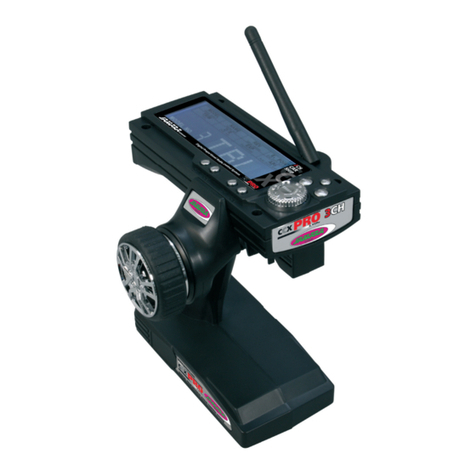
FCX6 Pro Tel
Emisora | Transmitter
No. 061260 throttle left
No. 061261 throttle right
13/16
ES - Información general
Jamara K. no se hace responsable de los
daños causados al producto en sí o por
medio de esto, a menos que esto se debe
al mal funcionamiento o errores de mane-
jo. El cliente solo tiene la responsabilidad
completa para el uso y manejo adecuado,
incluyendo, sin limitaciones, el montaje, el
proceso de carga, el uso de hasta la elec-
ción de la zona de aplicación. Por favor,
consulte las instrucciones de uso y funci-
onamiento, contiene información y avisos
importantes.
GB - General information
Jamara e.K. is not liable for any damage
caused to the product itself or by it, if this
is due to improper operation or handling
errors. The customer alone bears the full
responsibility for the proper use and hand-
ling, including in particular, assembling,
charging and using the model, and selec-
ting the area in which to use it. Please re-
fer to the operating and user instructions,
which contain important information and
warnings.
ES - Declaración de conformidad
Por medio de la presente, la empresa Jamara e. K. declara que el modelo‚ “FCX6 Pro Tel, No.
061260, No. 061261“ de conformidad con los requisitos esenciales y otras disposiciones pertinentes
de la Directiva 2014/53/EU y 2011/65/EU se encuentra.
Encontrará más información en: www.jamara-shop.com/Conformity
GB - Certifi cate of Conformity
JAMARA e.K. hereby declares that “FCX6 Pro Tel, No. 061260, No. 061261“ follow the regulati-
ons and requirements as well as any ther relivant directives of the EEC directive 2014/53/EU and
2011/65/EU.
Further information can also be found at: www.jamara-shop.com/Conformity
Nota sobre reciclado
Por favor, respete la normativa sobre reciclado de materiales eléctricos/electrónicos cuan-
do se deshaga de dispositivos de este tipo. Por favor, lleve a reciclar estos componentes.
Disposal instructions
All parts of this model should be disposed of correctly, in particular electronic components may be
subject to local restrictions. Your dealer will advise you.
Este modelo no es un juguete!
No apropriado para menores de 14 años.
Atención: Mantenga necesariamente lejos de niños menores de 36 meses. ASFIXIA!
Contiene piezas pequeñas.
This model is not a toy!
Not suitable for people under 14 year.
Warning: Keep away necessarily children under 36 months. RISK OF SUFFOCATION!
Contains small parts which can be swallowed.
Contenido del kit
• Emisora 2,4 GHz de 6 canales
• Receptor 2,4 GHz de 6 canales
• Jumper (Cable puente binding)
• Instrucciones
Box contents:
• 6 channel 2,4 GHz Transmitter
• 6 Channel 2,4 GHZ Receiver AFHDS 2A
• Link plug (binding pin)
• Manual
Accesorios recomendados:
Receptor FCX 6 Pro Tel 2,4 GHz Sensor No. 06 1263
Sensor Voltaje No. 06 1265
Sensor velocidad óptico No. 06 1266
Sensor velocidad magnético No. 06 1267
Sensor de temperatura No. 06 1268
Cable adaptador para simulador No. 06 5017
Recommended Accessories
Receiver FCX 6 Pro Tel 2,4 GHz Sensor No. 06 1263
Sensor Voltage No. 06 1265
Sensor rpm optical No. 06 1266
Sensor rpm magnetic No. 06 1267
Sensor Temperature No. 06 1268
Adapter cable for flight simulator No. 06 5017
Highlights
• 2,4 GHz AFHDS 2A Digital Proprtional Radio Control System
• AFHDS 2A / AFHDS On/OFF, utilizando el receptor del modelo anterior es posible!
• Ajuste de la tensión de la emisora (Low V, Alarm, High V)
• Fail Safe en AFHDS 2A Modo de canal 1 - 6 ajustable
• 6 canales
• 4 interruptores programables
• 2 potenciómetro programables
• Display grande digital
• Acro, menú de helicóptero
• Memoria para 20 modelos
• Servoinversión
• Delta
• Cola - V
• Dual Rate
• Expo
• Copia de los modelos
• Trainer/Buje de simulador
• 174 x 89 x 190 mm
• 392 g
Características técnicas - Receptor FCX 6 Pro Tel 2,4 GHz:
Banda 2,4 GHz
Tipo de modulación AFHDS 2A
Resolución de los servos 10 Bit (1024 niveles)
Tensión de trabajo 4 - 6,5 V DC
Dimensiones ~ 40,4 x 21,1 x 7,35 mm
Peso ~ 6,4 g
Features:
• 2.4GHz AFHDS 2A Digital proprtional Radio Control System
• AFHDS 2A / AFHDS can be switched on / off, thus, using the receivers of the previous
model possible
• Adjustment of transmitter voltage (low V, Alarm, High V)
• Fail Safe can be set in channel 1 – 6 in AFHDS 2A Mode
• 6 channel
• 4 programmable Switches
• 2 programmable Poti
• Display
• Acrobatics, Heli menu
• 20 Model Memory
• Servo-Reverse
• Delta
• V-Tail
• Dualrate
• Expo
• Copy existing models
• Trainer/Simulator socket
• 174 x 89 x 190 mm
• 392 g
Technical data Receiver FCX 6 Pro Tel 2,4 GHz
Frequency 2,4 GHz
Modulation AFHDS 2A
Servo resolution 10 Bit (1024 Schritte)
Operating voltage 4 - 6,5 V DC
Size ~ 40,4 x 21,1 x 7,35 mm
Weight ~ 6,4 g
2
ES - Sistema 2,4 GHz.
“AFHDS“ signi ca “Automatic Frequency Hopping Digital System“ – Sistema Digital de Salto de
Frecuencia Automático. Este so sticado sistema de radiotransmisión está basado en mucha expe-
riencia y le garantiza un gran alcance y larga duración de la batería. Este es el resultado de años
de investigación y de controles y convierte a Jamara en una empresa líder del mercado mundial.
Atención:
Rogamos lea estas instrucciones íntegras y solamente use su sistema de radiotransmisión acorde
a ellas. El abuso o mal uso de este sistema de radiotransmisión puede causar lesiones graves y
hasta lesiones con un resultado letal. Esta banda de transmisión de 2,4-GHz. se comporta de forma
totalmente distinta a las otras bandas de frecuencia conocidas hasta ahora. Siempre mantenga
su modelo al alcance de la vista, evite objetos grandes que podrían obstruir la señal HF, ya que
eso puede causar peligro, perdida de control y  nalmente la perdida del modelo. La señal RF de
2,4-GHz. se transmite en lineas rectas y no puede rodear objetos que se encuentren en su paso ni
mucho menos traspasarlos. Nunca toque la antena de la emisora mientras usa su modelo, ya que
esto puede reducir de forma signi cativa la calidad y la fuerza de la señal HF y puede causar peligro
que puede llevar a la perdida de control.
Atención:
Al poner el modelo en marcha, siempre encienda primero la emisora y después el receptor del mo-
delo. Al apagar el sistema, siempre desconecte primero el receptor y después apague la emisora.
Así evita que el receptor reciba alguna señal erronea, que puede causar movimientos de servo irre-
gulares. Esto es especialmente importante al usar un modelo, para evitar por ejemplo que arranque
el motor inesperadamente y así cause lesiones, en el peor caso hasta con resultados letales.
GB - 2,4 GHz System
AFHDS2A stands for „Automatic Frequency Hopping Digital System 2A“. This highly sophistica-
ted radio transmission system will guarantee you a long range, jamming free and long battery life
experience. This is the result of years of research and testing and makes Jamara one of the word
leader in the market.
Danger
Misuse of this radio system can lead to serious injuries or death. Please read completely this manual
and only operate your radio system according to it.
The 2,4 GHz radio band has a comletely different behavior than previously used lower frequency
bands. Keep always your model in sight as a large object can block the RF signal and lead to loss
of control and danger. The 2,4 GHz RF signal propagates in straight lines and cannot get around
objects on its path. Never grip the transmitter antenna when operating a model as it degrades signi-
 cantly the RF signal quality and strength and may cause loss of control and danger.
Danger
Always turn on the transmitter  rst then the receiver. When turning off the system, always turn off
the receiver  rst than the transmitter. This is to avoid having the receiver on itself as it may pick a
wrong signal and lead to erratic servo movements. This is particularly important for electric powered
models as it may unexpectedly turn on the motor and lead to injuries or death.
Dual Antena
Para llegar a las distancias máxima de seguridad entre la emisora y el receptor, por favor siga las
siguientes instrucciones:
1. Las dos antenas deben mantenerse lo más recto posible. De lo contrario se reduce el alcance.
2. Las dos antenas deben ser colocados a 90° entre sí, come se puede ver en las tres imágenes.
3. Las antenas deben mantenerse lejos de los materiales conductores como metal o  bra de
carbono (para los modelos con fuselaje de  bra de carbono, por ejemplo, traer la antena al
exterior). Para un funcionamiento seguro, es necesario una distancia mínima de 1,5 cm.
Materiales conductores tienen menos impacto en las partes coaxial de la antena pero es
importante que no se deforma la parte coaxiala a la luz intensa.
4. Mantener las antena lo más lejos posible del motor, regulador y otras fuentes de interferencia.
Dual antenna notes
In order to make sure maximum distance between the transmitter and receiver please follow the
directions below:
1. The two antennas must be kept as straight as possible. Otherwise, control range will be reduced.
2. The two antennas should be placed at a 90 degree angle to each other, as illustrated in the tree
pictures below.
3. The antennas must be kept away from conductive materials, such as metal and carbon. A dis-
tance
of at least 1,5 cm is required for safe operating. Conductive materials will not affect the coaxial
part
of the antenna, but it is important that the coaxials are not bend to a severe radius.
4. Keep antennas away from the motor, speed controller and other noise soures as much as
possible.
ES - Características del Sistema
Este sistema de radio trabaja con un rango de frecuencia entre 2,4 y
2,4835 GHz. Esta banda contiene 160 canales independientes. Cada
sistema de radio usa 16 canales distintos y 160 diferentes tipos de al-
goritmos de “Hopping“ (saltos). Al encenderse de forma individual, saltan
las frecuencias de esquema y las frecuencias de canal, y de esa forma el
sistema le puede garantizar una transmisión de radio impecable..
Este sistema de radio se aprovecha de una gran ampli cación y de la alta
calidad de su antena multi-direccional. Cubre toda la banda de frecuenci-
as. En combinación con la alta sensibilidad del receptor, este sistema de
radio garantiza una transmisión sin errores a largo alcance.
Cada emisora tiene una ID  ja. Al emparejar la emisora con un receptor, el
receptor memoriza dicha ID  ja y solamente podrá procesar datos de esta
emisora. Esto evita la contaminación con otras señales de emisión y au-
menta de forma drástica la resistencia a interferencias y la seguridad.
Este equipo de transmisión usa componentes de baja energía y un chip
en el receptor altamente sensible. El módulo HF usa una transmisión
de señales intermitente, así evitando un alto consumo de corriente. En
comparación con un sistema FM estándar, este sistema de transmisión
solamente necesita una décima parte de potencia.
Sistema AFHDS 2A es una función de reconocimiento automático, que
puede cambiar automáticamente de la modalidad actual y modalidad de
comunicación con la función de retorno de datos y permite de aplicar me-
jor el estado de trabajo actual para tener más diverción.
AFHDS 2A tiene una codi cación multicanal integrado y corrección de er-
rores, para mejorar la estabilidad de la comunicación, para reducir la tasa
de error y para obtener una mejor autonomía de una trasmisión  able.
GB - System Characteristic
This radio systems works in the frequency range of 2.4000 to 2.4835 GHz.
Thins band has been divided into 160 independent channels. Each radio
system uses 16 different channels and 160 different types of hopping al-
gorithm. By using various switch-on times, hopping scheme and channel
frequencies, the system can guarantee a jamming free radio transmission.
This radio system uses a high gain and high quality multidirectional anten-
na. It covers the whole frequency band. Associated with a high sensitivity
receiver, this radio system guarantees a jamming free long range radio
transmission.
Each transmitter has au unique ID. When binding with a receiver, the re-
ceiver saves that unique ID and can accepts only data from that unique
transmitter. This avoid picking another transmitter signal and dramatically
increases interference immunity and safely.
This radio system uses low power electronic components and a very sen-
sitive receiver chip. The HF modulation uses intermittent signal transmis-
sion thus reducing even more power consumption. Comparatively, this
radioa system uses only a tenth of the power of a standard FM system.
AFHDS2A system has the automatic identi cation function, which can
switch automatically current mode between single-way communication
mode with data return function can help users understand current working
status better and make the  ght more enjoyable.
AFHDS2A has built-in multiple channel coding and error-correction, which
improve the stability of the communication, reduce the error ratio and ex-
tend the reliable transmission distance.
3
2,4 GHz. Procedimiento
1. Emparejamiento – “Binding“
Como norma general se recibe el receptor con la emisora ya emparejada de fábrica, así que Ud. no
tendría que hacerlo. Sin embargo, si quiere utilizar otra emisora o receptor (siempre que sea de la
misma marca), primero tendrá que emparejarlos.
En dicho caso proceda de la siguiente manera :
1. Install batteries in the transmitter and turn it off.
2. Connect the binding jumper to the battery port of the receiver.
3. Connect the battery of the receiver to any channel power supply. The red LED with blink
indicating that it is in binding mode.
4. Press and hold the bind key of the transmitter and turn it on.
5. Se el LED rojo del receptor parpadea más lento, el proceso de binding está completo. Ahora
quando se tire el puente, el LED rojo se enciende de forma permanente.
6. Desconecte ahora el receptor de la corriente.
7. Después vuelva a encender la emisora.
8. Conecte todos los servos al receptor y conecte el receptor a la corriente.
9. Compruebe si todos los servos funcionan correctamente.
10. Si no fuera así, debe repetir todo el procedimiento desde el principio
11. Una vez que haya programado y ajustado su modelo, se debe repetir el proceso de binding,
para que el ajuste y los parámetros se trasmiten completamente desde la emisora/receptor.
2,4 GHz Operation notes
1. Binding
The supplied transmitter and receiver are already bound at production time so you don‘t need to
do it. If you are using another transmitter or receiver, you have to  rst bind them before use as
described below:
1. Install batteries in the transmitter and turn it off.
2. Connect the binding jumper to the battery port of the receiver.
3. Connect the battery of the receiver to any channel power supply. The red LED with blink
indicating that it is in binding mode.
4. Press and hold the bind key of the transmitter and turn it on.
5. The binding process is  nished when the red indicator on receiver fl ashes more slowly than
before. Pull out the binding wire and the red indicator stays on.
6. Disconnect the receiver battery.
7. Turn off then back on the transmitter.
8. Connect all the servos to the receiver then connect its battery.
9. Check if all servos are working as expected.
10. If anything is wrong, restart this procedure from the beginning.
11. Once you have programmed and set-up your model, you should bind once again so that the set
parameters are assigned tot he Transmitter/ Receiver.
Aeroplano
Aircraft
Helicóptero
Helicopter
ES - Receptor y el servo conexiones GB - Receiver and servo connections
para la batería
to battery
para la batería
to battery
toma de carga
Charging jack
toma de carga
Charging jack
Interruptor cable
Switch harness
Interruptor cable
Switch harness
Receptor
Receiver
Receptor
Receiver
Receptor
Receiver
CH6
CH6
CH6
CH5
CH4
CH3
CH2
CH2
CH2
CH1
CH1
CH1
Aileron modo
(2 servos de aleron separado)
CH 1 & 6
Flaperon mode
(dual aileron servo),
CH 1 & 6
independiente
de alerón y fl aps
(1 cada uno)
Independent Aileron & Flap
CH4
CH4
CH6
Gyro sensory (CH5), Timón (CH4)
Gyro sensory (CH5), Rudder (CH4)
Sistema Gyro opcional
Optional Gyro system
Servo del timón
Rudder servo
CH3
CH2
CH1
Receptor
Receiver
Batería
Battery
Saltador Binding
Binding jumper
4
Encender la emisora
Power ON
Desconectar la emisora
Power OFF
DE
2. Cómo activar
1. Poner todo junto.
2. Encienda el transmisor.
3. Conectar la batería al receptor.
4. El LED rojo se enciende permanentemente el receptor, lo que signi ca que la existencia de
una señal real.
5. El sistema se activa y se puede utilizar.
GB
2. Power on
1. Connect all parts.
2. Switch on the transmitter.
3. Connect the receiver battery.
4. The receiver red LED indicator is solid indicating the presence of a correct signal.
5. Use the radio system.
3. Apagar secuencia
1. Desconecte la batería del receptor
2. Apague el transmisor
3. Shut down
1. Disconnect the receiver battery.
2. Switch off the transmitter.
DE - Descripción gas izquierda
1 Antena 2,4 GHz
2 Botón VRB (Programable)
3 Interruptor B (Programable)
4 Interruptor A (Programable)
5 Modo 2 = Mando de paso/cola
Modo 4 = Mando de paso/alabeo
6 Trim de paso
7 Modo 2 = Trim de cola
Modo 4 = Trim de alabeo
8 Botón arriba
9 Botón abajo
10 LCD
11 Botón de encendido
12 Botón VAA (Programable)
13 Interruptor C (Programable)
14 Interruptor D (Programable)
15 Ojal para correa
16 Modo 2 = Mando alabeo/cabeceo
Modo 4 = Mando cabeceo/cola
17 Trim de cabeceo
18 Modo 2 = Trim de alabeo
Modo 4 = Trim de cola
19 Botón con rmación (Enter)
20 Exit/Atrás botón
21 Interruptor On/Off
22 Canal que desee introducir el cable simulador
23 Compartimento de la batería
GB - Defi nition of key funktions throttle left
1 2,4 GHz Antenna
2 Rotary poteniometer VRB (free programmable)
3 Switch B (free programmable)
4 Switch A (free programmable)
5 Mode 2 = Throttle/Rudder stick
Mode 4 = Throttle/Aileron stick
6 Throttle Trim
7 Mode 2 = Rudder Trim
Mode 4 = Aileron Trim
8 Key up
9 Key down
10 LCD Display
11 Bonding button
12 Rotary poteniometer VAA (free programmable)
13 Switch C (free programmable)
14 Switch D (free programmable)
15 Hook
16 Mode 2 = Aileron/Elevator stick
Mode 4 = Elevator/Rudder stick
17 Elevator Trim
18 Mode 2 = Aileron Trim
Mode 4 = Rudder Trim
19 Enter button
20 Exit / Back button
21 Power switch
22 Simulator connecter
23 Battery box
22
23
1
11
12
13
14
15
16
17
18
19
20
2
3
4
5
6
7
8
9
10 21
5
Atención:
Debido a un dispositivo de seguridad adicional, los 4 interruptores de la emisora
tienen que estar en posición “Off“ (apagados) al encender la emisora. Si este no
fuera el caso, aparecerá un aviso en la pantalla y además escuchará un sonido de
advertencia, hasta que todos los interruptores se encuentren en la posición correcta.
Warning:
For your safely, the 4 switches of the transmitter must be in their „off“ postition and
throttle stick must be the lowest position when turning the transmitter on. If not, a war-
ning screen will be displayed until all switches are in the right position.
ES - Descripción gas derecha
1 Antena 2,4 GHz
2 Botón VRB (Programable)
3 Interruptor B (Programable)
4 Interruptor A (Programable)
5 Modo 1 = Mando cabeceo/Cola
Modo 3 = Mando cabeceo/alabeo
6 Trim de cabeceo
7 Modo 1 = Trim de alabeo
Modo 3 = Trim de cola
8 Botón arriba
9 Botón abajo
10 LCD
11 Botón de encendido
12 Botón VAA (Programable)
13 Interruptor C (Programable)
14 Interruptor D (Programable)
15 Ojal para correa
16 Modo 1 = Mando de paso/alabeo
Modo 3 = Mando de paso/cola
17 Trimmung Gas
18 Modo 1 = Trim de cola
Modo 3 = Trim de alabeo
19 Botón con rmación (Enter)
20 Exit/Atrás botón
21 Interruptor On/Off
GB - Defi nition of key funktions throttle right
1 2,4 GHz Antenna
2 Rotary poteniometer VRB (free programmable)
3 Switch B (free programmable)
4 Switch A (free programmable)
5 Mode 1 = Elevator/Rudder stick
Mode 3 = Elevator/Aileron stick
6 Elevator Trim
7 Mode 1 = Aileron Trim
Mode 3 = Rudder Trim
8 Key up
9 Key down
10 LCD Display
11 Bonding button
12 Rotary poteniometer VAA (free programmable)
13 Switch C (free programmable)
14 Switch D (free programmable)
15 Hook
16 Mode 1 = Throttle/Aileron stick
Mode 3 = Throttle/Rudder stick
17 Throttle Trim
18 Mode 1 = Rudder Trim
Mode 3 = Aileron Trim
19 Enter button
20 Exit / Back button
21 Power switch
1
11
12
13
14
15
16
17
18
19
20
2
3
4
5
6
7
8
9
10 21
6
ES - Pantalla
1. Tipo de programa AFHDS2A 1. Tipo de programa AFHDS
2. Número del modelo 2. Número del modelo
3. Nombre del modelo 3. Nombre del modelo
4. Información de datos 4. Ajuste  no
5. Ajuste  no 5. Carga Pilas / Batería
6. TX Pilas / Batería 6. Tipo de modelo
7. RX Pilas / Batería 7. Ajuste  no
8. Tipo de modelo
9. Ajuste  no
1 En la pantalla se ve la Tipo de modulación (AFHDS2A o AFHDS) y siguiente información:
2. Número de modelo escogido (1 a 20): Se pueden memorizar hasta 20 modelos distintos en la
emisora y resulta muy fácil escoger el modelo deseado o cambiar de modelo.
3. Nombre del modelo: Puede asignarle un nombre (max. 8 dígitos) a cada modelo memorizado
para así encontrar mejor el modelo deseado.
4. AFHDS 2A: indica los datos de la telemetría
AFHDS: las cuatros barras de trimming indican la pocición del trimming
5. AFHDS 2A: las cuatros barras de trimming indican la posición del trimming
AFHDS: indicación de capacidad batería/pilas emisora
6. AFHDS 2A: como 5 de AFHDS!
AFHDS: muestra el tipo de modelo seleccionado
7. AFHDS 2A: indicación de capacidad batería/pilas receptor
AFHDS: las cuatros barras de trimming indican la posición del trimming
8. AFHDS 2A: muestra el tipo de modelo seleccionado
GB - Main screen
1. Program type AFHDS2A 1. Program type AFHDS
2. Model number 2. Model number
3. Model name 3. Model name
4. Data feedback 4. Left trim
5. Left trim 5. Battery
6. TX Battery 6. Mode type
7. RX Battery 7. Right trim
8. Mode type
9. Right trim
1. Besides the modulations type (AFHDS2A or AFHDS), the main screen displays the following
information:
2. Selected model number (1 to 20): 20 different models can be saved in the transmitter allowing
you to instantly switch to 20 different models.
3. Model name: each model can be named with a 8 characters name that allow you to easily
recognize the associated models.
4. AFHDS 2A: Shows the data of telemetry
AFHDS: The four trimming bars show the position of the set value
5. AFHDS 2A: The four trimming bars show the position of the set value
AFHDS: Shows capacity of transmitter battery
6. AFHDS 2A: As in point 5 - AFHDS
AFHDS: Shows the chosen model type
7. AFHDS 2A: Shows capacity of receiver battery
AFHDS: The four trimming bars show the position of the set value
8. AFHDS 2A: Shows the chosen model type
1
3
4
5
6
7
2
3
4
5
6
7
8
9
1
2
Menú Principal
El menú principal está dividido en dos secciones : Sistema y Setup. En el menú de sistema de
la emisora puede crear y memorizar los 20 modelos. Después el menú Setup le permite crear la
programación de los diferentes modelos. Para entrar en el menú principal desde la pantalla presi-
one la tecla “OK“ de forma prolongada. Para entrar desde el menú principal al menú de sistema,
presione brevemente la tecla “OK“. El punto deseado del sistema de sub-menús para seleccionar el
botón „UP“ y „DOWN“, desplazarse por lo que el elemento de programa apropiado y seleccionarlo
pulsando el botón „OK“ - de botón. Los ajustes respectivos son entonces el botón realizado con el
„Cancelar“ y con rmada. La mayoría de las pantallas siguientes serán procesados de acuerdo con
este esquema. Para cada con guración de memoria con el „OK“ - tecla para con rmar
Para salir de los puntos del menú, se usa la tecla „Cancel“.
1. Se escojen los parámetros con la tecla „OK“.
2. Utilice el botón „UP“ y „DOWN“ para cambiar el valor del parámetro seleccionado.
3. Pulse la tecla “OK“ para guardar las con guraciones y volver al parámetro anterior.
4. Pulse la tecla “Cancel“ para terminar con el parámetro sin guardar la nueva con guración y
volver al parámetro anterior.
Pulse la tecla “Cancel“ para volver a una pantalla anterior. Si la pulsa repetidamente, puede volver
hasta la pantalla principal.
Main Menu
The main menu is seperated into two sections, system and functions setup. The system menu
allows you to set up the transmitter and manage the 20 models. The function menu is used to set up
each model seperately. To enter the main menu, long press the „OK„ . Then use the „Up“ and „Down“
Key to select the desired submenue and press again „OK“. Then, use the „Up“ and „Down“key to
select the desired submenu and press again „OK“.
Most of following screens work according to this simple scheme:
1. Use the „OK“ key to select the parameter to modify.
2. Use the „UP“ and „Down“ key to modify the value of the selected parameter.
3. Long Press the „Cancel“ key to exit and save the new parameters.
4. Short Press the „Cancel“ key to exit without saving the new parameters.
To return to the previous screen, press the „Cancel“ key. You can
repeat that operation until the main screen.
Menú de Sistema System settings
7
ES - Escoger modelo
Con esta función puede escoger uno de los modelos activos de entre los 20 modelos disponibles.
También permite cambiar entre los 20 diferentes modelos, con gurar los parámetros necesarios,
guardar y volar de inmediato.
GB - Model select
Use this function to select the active model among the 20 available models. Doing so, you can set
up and save all required parameters to fl y 20 different models and switch instantly between them.
Nombre del modelo
Con esta función le asigna al modelo escogido un nombre. Escoja la letra deseada girando el dial y
después presione la tecla “OK“ para cambiar la letra del nombre.
Model name
Use this function to chance the name associated with the currently selected model. Press „OK“ to
select the letter of the name to change then use the “UP“ or “DOWN“ key to change the selected
letter.
Escoger el tipo de modelo
Use esta función para escoger el tipo de avión o helicóptero y sus opciones actuales de control.
Aparecerá el menú “Functions Setup“ acorde a lo elegido. La emisora soporta aviones con cola en
“V“ y helicópteros de paso  jo o de paso variable y diferentes tipos de plato cíclico con servos a
90 °, 120 ° y 140 °.
Type select
AFT (Collective und Cyclic Pitch Mixing) 90 °, 120 ° and140 °. Use this function to select the type of
aircraft or helicopter the current model is controlling. The „Functions setup“ menu will be  lled accor-
dingly. The transmitter supports airplanes (including V-tail con guration),  xed and variable pitch
helicopters and Swash AFT (Collective and Cyclic Pitch Mixing) 90°, 120° and 140°.
Copiar un modelo
Esta función le permite copiar la con guración del modelo de una memoria a otra. Los datos en la
memoria sobre la que se copia (si existen) se sobreescribirán, es decir que se perderán, y serán
sustituidos por los nuevos (copiados). Ya que esta orden implica borrar con guraciones existentes,
le exigirá una con rmación. Pulse la tecla “OK“ para ejecutar la copia, escoja “YES“ con el dial y
vuelva a pulsar “OK“ para con rmar la copia.
GB - Model copy
Use this function to copy one model settings to another. The target model settings will be deleted
and replaced by the source model settings. Since this command is destructive, a con rmation will
be asked. Press „OK“ to execute the copy, select „Yes“ with “UP“ or “DOWN“ key then press „OK“
again to con rm.
8
ES - Resetear un modelo
DEsta función resetea todas las con guraciones actuales de un modelo elegido a la con guración
estándar. Esta acción no afecta a los demás modelos. Esta función puede resultar útil, si un “Setup“
en particular no ha resultado satisfactorio y uno pre ere volver a empezar una con guración nueva
desde el principio. Debido a que esta orden implica borrar con guraciones existentes, le exigirá
con rmar este paso.
GB - Model reset
This function will reset the currently selected model to its default. The other models will not be affec-
ted. This can be useful when a setup is going nowhere and need a fresh start. Since this function is
destructive, a con rmation will be asked.
• Seleccionar el menú „RX-Setup“ y con rmar con el botón „OK“.
• La opcion del menú „AFHDS 2A“ ya está marcado se puede activar pulsando el botón „OK“.
• Con el botón „UP“ o „DOWN“ se puede desactivar la codi cación „AFHDS 2A“. En la pantalla
aparece la indicación „Off“.
• Con el botón „OK“ para guardar la con guración y en la pantalla aparece la codi cación
„AFHDS“. Aquí no se pueden realizar más ajustes.
• Pulsando repetidamente el botón „CANCEL“se vuelve al menú principal.
• Después se de debe ejecutar el proceso de binding.
• Para programar la emisora de nuevo en „AFHDS 2A“ repetir el todo de nuevo.
• Select ‚„RX Setup“ menu and and con rm by „OK“ button
• The menu item „AFHDS 2A“ is already selected and can be activated with the button „OK“.
• The buttons „UP“ or „DOWN“ switch the digital encoding „AFHDS 2A“ off. The display shows
„Off“.
• Pushing the button „OK“ saves the setting and the display shows the digital code „AFHDS“. If
the transmitter works with the digital code „AFHDS“, the menu „RX Setup“ only shows the digital
code as a setting option.
• Push the button „CANCEL“ repeatedly until you get back to the operating display.
• Then, a binding process has to be performed.
• Switch back to „AFHDS 2A“ according to the same principle as described above.
PPM Output
• Seleccionar el menú „RX Setup“ y con rmar con el botón „OK“.
• Seleccionar con el botón „UP“ o „DOWN“ la opción de menú „PPM-Output“ y activarlo con el
botón „OK“.
• Con el botón „UP“ o „DOWN“ se puede modi car esta con guración. En el display aparece „Off“
o ON.
• Con el botón „OK“ se almacena el ajuste.
• Premer repetidamente el botón „CANCEL“ se vuelva al menú principal.
PPM Output
• Select ‚„RX Setup“ menu and and con rm by „OK“ button
• Use the buttons „UP“ or „DOWN“ to select the menu item „PPM-Output“ and activate it with the
button „OK“.
• With the „UP“ or „DOWN“ button can be changed this setting. „OFF“ or „ON“ appears on the
display.
• Pushing the button „OK“ saves the setting.
• Push the button „CANCEL“ repeatedly until you get back to the operating display.
RX-Setup
Con esta emisora es posible controlar el receptor con la codi cación „AFHDS“ y „AFHDS2A“. La
emisora esta ayustada en el receptor incluso „AFHDS2A“. Para utilizar el receptor „AFHDS“ la
emisora debe ser cambiada y el receptor debe estar conectado en al emisora. Por favor, tenga en
cuenta el capítulo de binding en la página 3.
RX Setup
The transmitter enables you to receivers with the code „AFHDS 2A“ and „AFHDS“. Ex works, the
transmitter is set to the enclosed „AFHDS 2A“-encoded receiver. If you want to operate a receiver
with the code „AFHDS“, the transmitter must be switched  rst and then the receiver must be bound
to the transmitter. Please refer to the section Binding on page. 3
9
ES - Tensión del receptor
En dependencia de la tensión del receptor utilizado se puede ajustar en este menú los valores de
tensión, en el que la emisora muestra visualmente y acústicamente un advertimiento de descarga
profunda de la batería receptor.
En el momento que los valores de tensión regulable son interdependientes, puede ser necesario
aumentar el valor de la tensión para la batería completamente cargada, para despues tambien
inserir los valores de alarma más altos. Si los límites de valores establecido son más bajos, parpa-
dear cuando se utiliza la emisora en el display el símbolo de la batería para la batería receptor y la
emisora emite sonidos de aviso o sonidos de alarma.
• Baja tensión:
Establecer el valor mínimo de tensión. Emite un alarma acústico y el símbolo de la batería
receptor en el display parpadea, cuando el valor actual de tensión de la batería está inferior que
este valor.
• Tensión de alarma:
Ajuste la tensión de alarma. Emite un alarma acústico y el símbolo de la batería receptor en el
display parpadea, cuando el valor actual de tensión de la batería está inferior a este valor.
• Alta tensión:
Ajuste el valor máximo de tensión. La batería está completamente cargada, cuando el valor
efectivo de la tensión de la batería es igual a este valor.
GB - RX Battery
Depending on the receiver voltage supply used, this menu can be used to set the voltage values
where the remote control visually and acoustically displays threatening deep discharge.
Since the adjustable voltage values depend on each other, it may be required to increase the voltage
value for a fully charged rechargeable battery  rst, to then be able to enter higher alarm values as
well.
If the set thresholds are undercut, the battery icon for the receiver battery will fl ash at operation of the
remote control and the remote control transmitter will make warning or alarm sounds.
• Low voltage:
set the minimum voltage value. The battery is empty when the actual battery voltage value is
lower than this value.
• Alarm voltage:
set the alarm voltage. an audible alarm rings and the receiver battery icon in the top tray blinks
when actual battery voltage value is lower than this value.
• High voltage:
set the maximum voltage value. The battery is in full charge state when the actual battery
voltage is equal to this value.
Fail Safe
Su emisora ofrece en el caso de una pérdida del señal la posibilidad de posicionar los servos au-
tomáticamente en una posición especí ca. Por ejemplo, un velero que está fuera de su alcance el
motor se apaga y comienza a volar en un círculo.
Ajustes:
Pulse brevemente „OK“, seleccione el canal que desea. Con „UP“ o „DOWN“ se puede cambiar el
canal de „OFF“ en „ON“ o utilizar invertido. Para hacer el ajuste deseado, mover la palanca de con-
trol en la posición deseada y pulse el botón „CANCEL“. La pantalla vuelva en la lista de los canales
y muestra el valor porcentual del canal seleccionado. Pulsando de nuevo el botón „CANCEL“ se
almacenan los valores.
Fail Safe
This function is used for setting the data of failsafe. Once the signal of receiver is lost, the one
or more servos will back to preset position. „turn off“ means the relevant servos will keep the last
position when the signal is lost.
Setting methods:
Short press „OK“, choose one channel to set failsafe function, if the channel is in the needed po-
sition, and keep it, short press „OK“, than the position of servo will be saved. „ALL Channels“ is
used for setting all activated channels at a time. Press „Chancel“ after  nishing all setting to save
the failsaft data.
Lista de sensores
Si en un receptor I-BUS estan conectados varios sensores (hasta 15 sensores), estos sensores se
muestran en este menú.
Sensor list
If shows al sensors`type, code and value, it can connect 15 sensors at most.
Elegir el sensor
La pantalla principal puede mostrar tres valores del sensor, con esta función se puede seleccionar
varios sensores, que se van a mostrar.
Choose sensor
Main screen can show 3 sensors‘ value, this function can select sensor which need to show, if you
don‘t select sensor, it will show teh default one.
10
ES - Speed-distance
Sensor de velocidad:
Utilizar el sensor deseado. Si no hay seleccionado uno, esta función se desativa.
Ajuste del sensor - velocidad:
Ajuste el sensor de velocidad correspondiente de la distancia de un vehículo. Este valor se utiliza
para controlar la velocidad vertical y el sensor del cuentakilómetros.
Reset Odometer:
Toque el „Reset Odometer 1“ o „Reset Odometer 2“, para restablecer el odómetro correspondiente.
Odometer 1: es para detectar la distancia recorrida a tiempo del vehículo.
Odometer 2: es para detectar la distancia recorrida del vehículo.
GB -Speed-distance
Speed sensor:
Select the rotation speed sensor to use. If none is seledted, this function is disabled.
Set rotation length:
Set the vehicle travel distance corresponding to one rotation speed sensor. This distance is used to
control the virtual speed and odometers sensor.
Reset odometer:
Touch „Reset odometer 1“ or „Reset odometer 2“ to reset the corres ponding odometer.
Odometer 1: it is used for recording the distance traveled by the vehicle on time.
Odometer 2: it is used for recording the distance traveled by the vehicle.
i-Bus Setup
Esta función se utiliza para ampliar el canal de datos.
i-Bus Setup
This function is used to expand data channel.
Servos freq
Con el botón „UP“ o „DOWN“ se puede ajustar la frecuencia-servo deseada. Cuando se pulsa el
botón „OK“ y se mantiene, se accede a los parámetros.
Atención!
En los servos analógicos no se puede superar la frecuencia-servo 50Hz, de lo contrario los servos
se destruyen. Si está utilizando servos digitales, el ajuste del valor depende del valor máximo de el
servo más lentos, el valor ajustado es efectivo para todas las salidas del receptor.
Servos freq
Use the buttons „UP“ or „DOWN“ to set the desired servo control frequency. If the button „OK“ is
pushed and held, the factory parameters are called.
Important!
When using analogue servos, the servo control frequency must not exceed 50 Hz, since the servos
are otherwise destroyed. If you operate only digital servos at the receiver, the value to be set is
according to the maximum value of the slowest servo, since the set value is effective for all receiver
outputs.
Modo Profesor
Esta función le permite unir dos emisoras enchufando un cable profesor/alumno en el conector
situado en la parte trasera de la emisora. Una emisora se convierte en emisora profesor (Maes-
tro) y la otra en emisora alumno (Esclavo). Una vez activado el modo profesor/alumno (Entre-
nador), se cambia del profesor al alumno usando el interruptor asignado en la emisora profesor.
La emisora del alumno puede ahora pilotar el modelo usando la señal de la emisora del profesor.
Cuando se desconecta la emisora del alumno con el interruptor de la emisora del profesor, el
profesor vuelve a recuperar el control absoluto sobre el modelo y le permite, por ejemplo, sacarlo
de una situación peligrosa.
Trainer mode
This function allows you to connect 2 transmitters together using a dedicated cable (No. 091551)
connected to the back interface. One is the instructor (Trainer) and the other is the student (Stu-
dent). Once enabled, switching on the selected trainer switch will set up the remote as the inst-
ructor and use the student signal to control the model. As soon as the trainer switch is turned off,
the instructor regains control and can for example recover the model from a hazardous position.
11
ES - Modo Alumno
Esta función trabaja en relación con el modo profesor. ¡Para el modo profesor/alumno la emi-
sora del alumno tiene que estar apagada ! Una vez activado dicho modo, no se tienen en
cuenta las con guraciones de modelos de la emisora alumno y los ordenes de control son envi-
ados directamente a la emisora profesor, y se pilotan los modelos con las con guraciones de la
emisora profesor. Quiere decir, que la emisora alumno puede intercambiar datos con cualquier
receptor que esté emparejado con la emisora profesor y puede pilotar cualquier modelo guarda-
do en la emisora profesor. Para evitar averías con el modo profesor/alumno activado, la emisora
profesor no tiene en cuenta las con guraciones de la emisora alumno y solamente se usan
con guraciones de la emisora profesor.
GB - Student mode
This function works together with the trainer mode. Once enabled, all model settings are by-
passed and the sticks position is send directly to the instructor‘s transmitter. At that time, the
student transmitter must not control any model directly and any receiver bound to the student
transmitter must be turned off. Bypassing all student settings allows both student and instructor
to share the instructor settings to avoid any glitch when switching between the student and his
instructor.
Modos de Control
Esta función le permite escoger entre 4 diferentes modos de control. Los primeros 4 canales
serán distribuidos de cuatro formas posibles, que puede escoger según sus costumbres de piloto.
(p.Ej.: Acelerador a la izquierda o acelerador a la derecha).
Stick mode
With this function, you can choose among 4 different sticks modes. The 4  rst channels are
mapped to the selected sticks according to your fl ying habits (left or right handed for example).
Versión del Firmware
Esta pantalla le muestra la versión de su  rmware y la fecha de su versión. Esto le permite discer-
nir si quizá existe una versión mas nueva para actualizar como “Update“ (ver “Firmware Update“).
GB - Firmware version
This screen displays the  rmware version and date. This allows you to know if a newer version
is as avialable for update (see below).
Luminosidad LCD
Se puede modi car las luminosidad de la pantalla LCD, para adecuar el “Display“ a las condi-
ciones de luz del entorno.
LCD brightness
Adjust the screen contrast according to the surrounding light environment.
12
Restablecimiento de los ajustes de fábrica
Con la ayuda de esta función tienen la posibilidad de restablecer todos los datos de todos los
modelos de memoria con un único comando.
Atención!
Si utiliza esta función, se eliminarán todos los datos de los modelos y con guraciónes! La emi-
sora se restablece a la con guración de fábrica y todos los datos deben ajustarse nuevamente.
Factory reset
With this function you have the option of deleting all the data of all model memories to their factory
settings with a single command.
Attention!
When you call this function, all previously entered model data and settings are
deleted! The remote control is returned to the delivery condition and all data must be entered
again.
DE - Firmware Update
Para actualizar el software en la emisora, debe estar conectado la emisora con un cable inter-
face-USB al ordenador. La emisora debe ser puesto en el modo Update, de modo que los datos
se trans eren. Asegúrese de que los receptores que están conectado con la emisora estan
apagados.
GB - Firmware update
Prior activating this function, connect the USB cable between the back interface of the transmitter
and a PC computer. A con rmation will be asked since all functions will be halted. Turn off any
receiver before entering this mode. To exit this mode, simply turn off then back on the transmitter.
Confi guración de las funciones Functions settings
Inversión de servos
Esta función le permite invertir un canal. Con gure todos los canales de modo que cada uno
funcione en la dirección correcta de su modelo.
Reverse
This funktion allows you to reverse a channel. Set all channels according to your model mecha-
nics.
Confi guración de la aeronave Confi guración del helicóptero
Recorrido Máximo
Con esta función con gura los recorridos máximos de los servos correspondientes a cada ca-
nal. Escoja el número de canal con la tecla “OK“ y cambie el porcentaje girando el dial. Pueden
cambiarse los recorridos para cada lado del canal. Para escoger que lado del canal quiere gra-
duar, empuje la palanca hacia el lado correspondiente. Escoja los diferentes valores según las
necesidades de su modelo.
End points
This function sets the lower and upper extents of all channels. Select the channel number with the
„OK“ key and the lower or upper extenby moving the corresponding stick or variator to the desired
direction. Select each extent value according to your model mechanics.
13
ES - Display
Esta pantalla le muestra el estado de los 6 canales, tal como están programados en la emisora
para el modelo elegido. Contiene todas las con guraciones de modo y algoritmos, siempre que el
modo alumno no esté activado.
GB - Display
This screen displays the status of all the 6 channels like they are transmitter to the model. It‘s
includes all the mode settings and algorithms if the student mode is not activated.
Canales Auxiliares
Esta función le permite escoger la fuente de los canales 5 y 6. Puede tratarse de un interruptor
o de una ruleta de control. Si se ha escogido un interruptor (avión), dicho interruptor enciende /
apaga la función deseada. Si se usa un helicóptero de paso variable, el canal 6 no está disponi-
ble como canal auxiliar. Cuando está en uso el control remoto de un giróscopo (helicóptero), el
canal 5 no está disponble como canal auxiliar.
Auciliary channels
This function let you choose the source of the channels 5 and 6. It can be a variator or a switch. If
a switch is selected, an off switch will tranmit the lower extent of the channel an an on switch the
upper extent. If a variable pitch helikopter is in use, the channel 6 is unavailable. If a helicopter
gyroscope is activated, the channel 5 is unavailable.
Subtrim
Esta función le permite con gurar el punto central de cada servo. Esto resulta especialmente útil,
cuando no es posible con gurar el punto central de forma mecánica.
Sub trim
This funktion allows you to adjust the middle point of each servo. This is especially useful when
this middle point cannot be mechanically  ne adjusted.
Dualrate / Exponencial
Esta función le permite modi car la Expo + Dual Rate de los canales 1, 2, y 4 tanto en el modo
normal como en el modo sport. Use el interruptor del modo de vuelo (SWA) para cambiar entre
el modo normal y el modo sport. El porcentaje interviene en el coe ciente de la inclinación y la
linearidad de la curva exponencial. Esto resulta muy útil, para atenuar la sensibilidad del mando
en el recorrido central de la palanca.
Dual rate / exponential
This function lets you set up the transfer function of the channel 1, 2, und 4 in both normal and
sport mode. Use the fl y mode switch to change mode. The rate selects the desired slope coef ci-
ent and the exponential the linearity of the curve. This is very useful to decrease the sensitivity
near the middle point.
Curva de Gas (Aceleración)
Esta función sirve para con gurar la proporción de aceleración aplicada para cada posición de
la palanca de acelerador (canal 3) en modo normal y punto muerto. Use el interruptor “Standby-
Mode“ (SWB) para cambiar de modo normal a Idle-Up. Se pueden con gurar 5 puntos de curva.
Por ejemplo, en el caso de un motor de explosión, un principiante puede disminuir la sensibilidad
de la válvula de estrangulación un 0, 5, 10, 15 y 20% para suavizar la linearidad.
Throttle curve
This function sets up the transfer curve of the throttle (channel 3) in both normal and idle up
modes. Use the idle mode switch to change mode. 5 key points can be adjusted. For example, a
beginner may set them to 0,5, 10, 15 and 20% to decrease the throttle sensitivity and keep its
linearity.
14
ES - Curva de Paso (sólo helicópteros)
Esta función es similar a la función “curva de gas“ y sirve para regular el ángulo de las palas
principales en cada posición de la misma palanca de gas.
GB - Pitch curve (variable pitch helicopter only)
This function is similar to the „Throttle curve“ and sets up the transfer curve of the pitch.
Swash AFR (sólo helicópteros de paso variable)
Con esta función modi ca el valor de los movimientos de alabeo, cabeceo y paso del plato
cíclico. Para invertir dicho valor, cambie el signo (positivo o negativo) del valor numérico de cada
movimiento.
Swash AFR (variable pitch with Swash AFT helicopter only)
This function sets the proportion of aileron, elevator and pitch in the Swash AFR. To invert one of
them, a negative value must be selected.
Mix
Esta función le permite la con guración de hasta 3 mezcladores, para poder mezclar los diferen-
tes canales y sus funciones de control. El canal maestro interviene sobre el comportamiento del
canal esclavo. Con esto podemos conseguir que dos canales trabajen juntos. El signo positivo
o negativo del porcentaje va a intervenir en la dirección de funcionamiento del canal esclavo. El
“Offset“ regula el porcentaje de movimiento del canal esclavo.
Mix
This function allows you to program up to 3 custom channel mixes. The master channel will alter
the slave channel. The positive and negative mix set the amount of alteration above and below
the middle point. The offset shifts the slave channel by a certain amount.
Elevon (solo avióne)
Activar esta función, si está volando un modelo delta o monoala. Ajustar la parte del alerón (canal
1) y timón de profundidad (canal 2) en el mixer de acuerdo a su modelo.
Elevon (Airplane only)
For the model without tail and the delta wing, you can set mix control rates of Aileron (CH1) and
Elevator (CH2) by this function.
Cola en V (sólo aviones)
Active esta función si pilota un avión con cola en V. Con gure la proporción del canal de alabeo
(canal 1) con la de elevador (canal 2) con la mezcla correspondiente a su modelo.
V-tail (Airplane only)
For the model without the V-tail, you can set mix control rates of Elevator (CH2) and Rudder
(CH4) by this function.
15
ES - Giróscopo (sólo helicópteros)
Esta función le permite activar el giróscopo en el canal 5 y con gurar valores tanto para vuelo
normal como vuelo acrobático.
GB - Gyroscope (Helicopter only)
This function allows you to activate the gyroscope on the channel 5 and to set up its value for
both normal and idle up modes.
Asignar Interruptores
Esta función le permite asignar interruptores a los diferentes modos de vuelo.
Switches assign
This function lets you assign a switch to conrol the fl y mode, idle mode and throttle hold functions.
Autorotación (sólo helicópteros)
Esta función le permite activar el modo de autorotación y escoger los valores de la curva. Una
vez activado, se ignora la curva de paso y se ciñe a los valores de la curva de autorotación.
Throttle hold
This function allows you to activate the throttle hold and to choose its value. Once engaged, the
throttle stick is ignored and only the selected value is transmitted.
Medidas de Seguridad
● Lea atentamente este manual y sobre todo nuestras medidas de seguridad.
● Si esta es la primera vez que tenga a un radio control/emisor póngase en
contacto con una persona que tenga experiencia con RC y pida ayuda.
● Esta estación fue hecha especialmente para los modelos de coches.
● La Compañía Jamara no se hace responsable por cualquier pérdida o defecto
de mal uso.
● Modelos de control remoto no son juguetes, no debe estar en manos de los
niños menores de 14 años de edad, sólo en la presencia de un responsável.
● Para el funcionamiento del producto se requiere conocimientos técnicos y buena
habilidad con las manos. Fallos o dejar que se moje, el producto puede dañarse
y hacer daño.
● El fabricante y el vendedor no pueden infl uir en cómo manejar un juguete,
dejando claro que hay peligro si este producto ha sido usado incorrectamente.
Así que no nos hacemos responsables por los daños causados por el mal uso.
● También es posible que incluso si la emisora esta desconectada, pueda causar
problemas con el receptor y causar daños.
● Proceder con cuidado identi cado antes de que el uso del mando a distancia.
mantener lea las instrucciones de seguridad de este
● Preste atención a las medidas de seguridad, en primer lugar encender la
emisora y luego la estación del modelo. Cuando quieras apagar hacer
exactamente lo contrario, el modelo y luego el receptor de la emissora.
● Utilize sólo el receptor original. Si utiliza otro receptor no tendrá ningún vínculo
con la banda de 2.4 GHz.
● Proteger la red contra el polvo, la suciedad y la humedad.
● No lo deje en un lugar cálido y no muy calientes o muy frío o en lugar del autor
vibração. Usarlo sólo en lugares de no más de temperatura -10 a 40C °.
● Use el cargador de alta calidad, se encuentra en el catálogo. Declaraciones
correcta de nuestro fabricante recomienda.
● Evitar golpes y presiónes. Controlar regularmente la emisora y el receptor si
tienen daños en la caja, conectores y cables.
● Los componentes dañados o mojado, no se tienen que utlizar mas, aunque si
estan seco. O comprobar en nuestro servicio o tienes que cambiar las piezas!
ATENCIÓN!
● Es producto no es para personas (incluidos niños) con discapacidad física,
mental y sensonriais. O ninguna experiencia ni conocimiento, a menos que
vayan acompañados de un responsable o recibir instrucciones ¿Cómo se debe
usar. Los niños deben ser supervisados para asegurarse de que no te metas con
el producto.
Safety Information
● Read these instructions carefully before use paying particular attention to the
safety notes.
● If this is your first venture into radio controlled modelling we strongly recommend
that you seek the help of an experienced modeller before you begin.
● This Radio control system has been exclusively designed for use with models
designed to be remotely controlled and as such may only be legally operated as
such.
● The company JAMARA accept no responsibility whatsoever if his product is used
in any other way.
● Radio Controlled models, in particular aircraft, are not toys and as such and
should only be operated by children or youths if closely supervised by a
responsible adult.
● Building and operating such models requires a degree of skill, understanding
and technical knowhow as well as a responsible attitude. Faults in the
construction or irresponsible behaviour could lead to serious damage or injury.
● As neither the manufacturer or retailer has any influence over the correct use of
modelling products we wish to emphasise these safety instructions and will in no
way be held responsible for the misuse of our products.
● Please be aware that the receiver system can also create a danger if operated
when the transmitter is not switched on.
● Always operate the transmitter with extreme caution and follow the instructions
listed here.
● Always switch the transmitter on before the receiver and switch off in the
opposite order.
● Only use our original receivers as any other brand of 2.4 GHz receivers will not
bond to our transmitters.
● Protect the system from dust, dirt and moisture.
● Never expose the system to extreme heat, cold or vibration. The system should
only be operated between -10° and + 40°C.
● Use a good quality charger selected from our range and follow the battery
manufacturers instructions.
● Avoid exposing the system to impact or vibration and inspect all of the
components regularly for damage to the casing, plugs, sockets and cables.
● If any component gets damaged or is exposed to water do not use it even if it has
been dried out! Any such component should be replaced or returned to our
service department.
ATTENTION!
● This product is not intended for use by individuals (including children) with
reduced physical, sensory or mental capabilities or lack of experience and / or
knowledge, unless they are supervised by a person responsible for their safety
and is able to give instructions about how the product should be used. Children
should be supervised to ensure that they do not play with the product.
JAMARA e.K.
Inh. Manuel Natterer
Am Lauerbühl 5 - DE-88317 Aichstetten
Tel. +49 (0) 75 65/94 12-0 - Fax +49 (0) 75 65/94 12-23
[email protected] ●www.jamara.com
Service - Tel. +49 (0) 75 65/94 12-66
kundenservice@ jamara.com
Salvo error o modicación técnica. Copyright JAMARA e. K. 2016
Prohibida su reproducción o distribución, por cualquier medio, salvo consentimiento expreso de JAMARA e. K.
All rights reserved. Copyright JAMARA e.K. 2016
Copying or reproduction in whole or part, only with the expressed permission of JAMARA e.K.
Reitter Modellbau Versand
Patricia Reitter
Degerfeldstrasse 11
72461 Albstadt
Tel 07432 9802700
Fax 07432 2009594
Mail [email protected]
Web www.modellbauversand.de
Extra Trade
Rudolf Müller & Gerrit Müller GdbR
Lindenstraße 82
66787 Wadgassen
Tel 06834 9604952
Fax 06834 9604963
Mail [email protected]
Web www.extra-trade.de
Sigi‘s Modellbau Shop
Siegfried Costa
Bundesstr. 30
AT -6923 Lauterach
Tel +43 557483657
Fax +43 557483657
Mail [email protected]
Web www.playland-modellbau.at
Modellbau Zentral
Peter Hofer
Bresteneggstrasse 2
CH -6460 Altdorf
Tel +41 794296225
Fax +41 418700213
Mail [email protected]
Web www.modellbau-zentral.ch
Bay-Tec Modelltechnik
Martin Schaaf
Am Bahndamm 6
86650 Wemding
Tel 07151 5002192
Fax 07151 5002193
Mail [email protected]
Web www.bay-tec.de
DE DE
DE
Aigner Modellbau
Edmund Aigner
Graben 2
AT -3300 Amstetten
Tel +43 747224655
Fax +43 747223358
Mail of[email protected]
Web www.modellbau-amstetten.at
CH
AT AT
ES - Servicio asistencia GB - Service centre

Other manuals for FCX6 Pro Tel

8

This manual suits for next models

2

Other Jamara Transmitter manuals

Jamara FCX6 Pro Tel User manual

Jamara

Jamara FCX6 Pro Tel User manual

Jamara FCX6 Pro Tel User manual

Jamara

Jamara FCX6 Pro Tel User manual

Jamara Compa 2,4 GHz User manual

Jamara

Jamara Compa 2,4 GHz User manual

Jamara Compa User manual

Jamara

Jamara Compa User manual

Jamara SCX User manual

Jamara

Jamara SCX User manual

Jamara CCX Pro 2,4 GHz User manual

Jamara

Jamara CCX Pro 2,4 GHz User manual

Jamara Compa X3 Evo User manual

Jamara

Jamara Compa X3 Evo User manual

Jamara CCX Pro 2,4 GHz User manual

Jamara

Jamara CCX Pro 2,4 GHz User manual

Jamara CCX Pro User manual

Jamara

Jamara CCX Pro User manual

Jamara Compa X3 Evo User manual

Jamara

Jamara Compa X3 Evo User manual

Jamara CCX Lipo 2,4 GHz 3 CH User manual

Jamara

Jamara CCX Lipo 2,4 GHz 3 CH User manual

Jamara CCX Pro 2,4 GHz User manual

Jamara

Jamara CCX Pro 2,4 GHz User manual

Jamara CCX Pro User manual

Jamara

Jamara CCX Pro User manual

Jamara CCX Lipo User manual

Jamara

Jamara CCX Lipo User manual

Jamara FCX6 Pro Tel User manual

Jamara

Jamara FCX6 Pro Tel User manual

Jamara CCX Lipo User manual

Jamara

Jamara CCX Lipo User manual

Jamara SCX 2,4 GHz User manual

Jamara

Jamara SCX 2,4 GHz User manual

Jamara CX 2,4 GHz User manual

Jamara

Jamara CX 2,4 GHz User manual

Jamara CCX Pro User manual

Jamara

Jamara CCX Pro User manual

Jamara CCX Pro 2,4 GHz User manual

Jamara

Jamara CCX Pro 2,4 GHz User manual

Jamara CCX Pro User manual

Jamara

Jamara CCX Pro User manual

Jamara FCX6 Pro Tel User manual

Jamara

Jamara FCX6 Pro Tel User manual

Jamara CCX Lipo 2,4 GHz 3 CH User manual

Jamara

Jamara CCX Lipo 2,4 GHz 3 CH User manual

Jamara FCX6 Pro Tel User manual

Jamara

Jamara FCX6 Pro Tel User manual

Popular Transmitter manuals by other brands

ABB LST300 Series Operating	 instruction

ABB

ABB LST300 Series Operating instruction

Rice Lake 20 series Technical manual

Rice Lake

Rice Lake 20 series Technical manual

RKI Instruments M2A Operator's manual

RKI Instruments

RKI Instruments M2A Operator's manual

Sennheiser SYSTEM 2020 Instructions for use

Sennheiser

Sennheiser SYSTEM 2020 Instructions for use

Honeywell PEHA FU-BLS Installation and operating instructions

Honeywell

Honeywell PEHA FU-BLS Installation and operating instructions

JUMO JUMO dTRANS p20 DELTA operating instructions

JUMO

JUMO JUMO dTRANS p20 DELTA operating instructions

Azbil JTD910S user manual

Azbil

Azbil JTD910S user manual

Autrol ATT2100 Operation manual

Autrol

Autrol ATT2100 Operation manual

Sennheiser SKP 100 G3 instruction manual

Sennheiser

Sennheiser SKP 100 G3 instruction manual

BWI Eagle AIR-EAGLE SR PLUS 36-1400-2B-120VAC Product information bulletin

BWI Eagle

BWI Eagle AIR-EAGLE SR PLUS 36-1400-2B-120VAC Product information bulletin

GE MASTR II Maintenance manual

GE

GE MASTR II Maintenance manual

Horizon Hobby REVOLUTION RVOF1106 manual

Horizon Hobby

Horizon Hobby REVOLUTION RVOF1106 manual

Electronics Line EL-2714 quick start guide

Electronics Line

Electronics Line EL-2714 quick start guide

YOKOGAWA SC202G (S) user manual

YOKOGAWA

YOKOGAWA SC202G (S) user manual

Emerson Rosemount 148 quick start guide

Emerson

Emerson Rosemount 148 quick start guide

Elsema FMT15101E manual

Elsema

Elsema FMT15101E manual

Shure AXT200 instruction manual

Shure

Shure AXT200 instruction manual

Audiovox UltraGuard UG-OE3 Programming guide

Audiovox

Audiovox UltraGuard UG-OE3 Programming guide

manuals.online logo
manuals.online logoBrands
  • About & Mission
  • Contact us
  • Privacy Policy
  • Terms and Conditions

Copyright 2025 Manuals.Online. All Rights Reserved.